Page 421 of 2890

B2M0764A
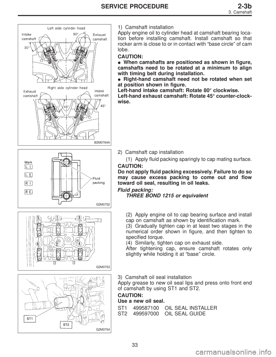
1) Camshaft installation
Apply engine oil to cylinder head at camshaft bearing loca-
tion before installing camshaft. Install camshaft so that
rocker arm is close to or in contact with“base circle”of cam
lobe.
CAUTION:
�When camshafts are positioned as shown in figure,
camshafts need to be rotated at a minimum to align
with timing belt during installation.
�Right-hand camshaft need not be rotated when set
at position shown in figure.
Left-hand intake camshaft: Rotate 80°clockwise.
Left-hand exhaust camshaft: Rotate 45°counter-clock-
wise.
G2M0752
2) Camshaft cap installation
(1) Apply fluid packing sparingly to cap mating surface.
CAUTION:
Do not apply fluid packing excessively. Failure to do so
may cause excess packing to come out and flow
toward oil seal, resulting in oil leaks.
Fluid packing:
THREE BOND 1215 or equivalent
G2M0753
(2) Apply engine oil to cap bearing surface and install
cap on camshaft as shown by identification mark.
(3) Gradually tighten cap in at least two stages in the
numerical order shown in figure, and then tighten to
specified torque.
(4) Similarly, tighten cap on exhaust side.
After tightening cap, ensure camshaft rotates only
slightly while holding it at“base”circle.
G2M0754
3) Camshaft oil seal installation
Apply grease to new oil seal lips and press onto front end
of camshaft by using ST1 and ST2.
CAUTION:
Use a new oil seal.
ST1 499587100 OIL SEAL INSTALLER
ST2 499597000 OIL SEAL GUIDE
33
2-3bSERVICE PROCEDURE
3. Camshaft
Page 425 of 2890

G2M0759
1) Remove hydraulic lash adjusters.
2) Compress the valve spring and remove the valve spring
retainer key. Remove each valve and valve spring.
ST1 498267600 CYLINDER HEAD TABLE
ST2 499718000 VALVE SPRING REMOVER
CAUTION:
�Mark each valve to prevent confusion.
�Use extreme care not to damage the lips of the
intake valve oil seals and exhaust valve oil seals.
G2M0760
C: INSPECTION
1. CYLINDER HEAD
1) Make sure that no crack or other damage exists. In
addition to visual inspection, inspect important areas by
means of red check.
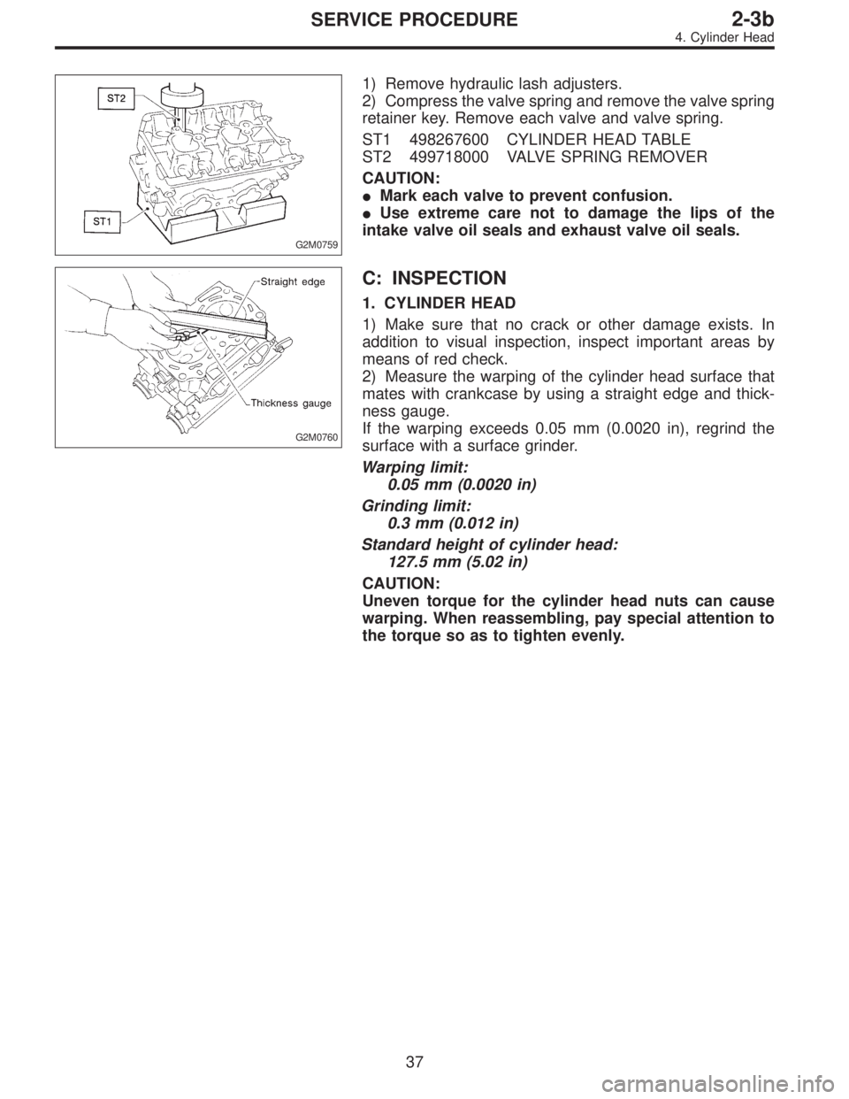
2) Measure the warping of the cylinder head surface that
mates with crankcase by using a straight edge and thick-
ness gauge.
If the warping exceeds 0.05 mm (0.0020 in), regrind the
surface with a surface grinder.
Warping limit:
0.05 mm (0.0020 in)
Grinding limit:
0.3 mm (0.012 in)
Standard height of cylinder head:
127.5 mm (5.02 in)
CAUTION:
Uneven torque for the cylinder head nuts can cause
warping. When reassembling, pay special attention to
the torque so as to tighten evenly.
37
2-3bSERVICE PROCEDURE
4. Cylinder Head
Page 432 of 2890
(7) Further tighten all bolts by 80 to 90°in numerical
sequence.
CAUTION:
Ensure that the total“re-tightening angle”[steps (6)
and (7) above] do not exceed 180°.
3) Install oil level gauge guide attaching bolt (left side
only).
2. INTAKE MANIFOLD
1) Install camshafts, rocker cover and related parts.
G2M0750
Tightening torque: N⋅m (kg-m, ft-lb)
T1: 10±0.7 (1.0±0.07, 7.2±0.5)
T2: 20±2 (2.0±0.2, 14.5±1.4)
44
2-3bSERVICE PROCEDURE
4. Cylinder Head
Page 453 of 2890
D: ASSEMBLY
1. CRANKSHAFT AND PISTON
B2M0127A
Tightening torque: N⋅m (kg-m, ft-lb)
T: 44±2 (4.5±0.2, 32.5±1.4)
1) Install connecting rod bearings on connecting rods and
connecting rod caps.
CAUTION:
Apply oil to the surfaces of the connecting rod bear-
ings.
2) Install connecting rod on crankshaft.
CAUTION:
Position each connecting rod with the side marked
facing forward.
3) Install connecting rod cap with connecting rod nut.
Ensure the arrow on connecting rod cap faces the front
during installation.
CAUTION:
�Each connecting rod has its own mating cap. Make
sure that they are assembled correctly by checking
their matching number.
�When tightening the connecting rod nuts, apply oil
on the threads.
65
2-3bSERVICE PROCEDURE
5. Cylinder Block
Page 455 of 2890
B2M0087A
2. CYLINDER BLOCK
1) Install ST to cylinder block, then install crankshaft bear-
ings.
ST 499817000 ENGINE STAND
CAUTION:
Remove oil the mating surface of bearing and cylinder
block before installation. Also apply a coat of engine
oil to crankshaft pins.
2) Position crankshaft on the #2 and #4 cylinder block.
Tightening torque:
T1: 25±2 N⋅m (2.5±0.2 kg-m, 18.1±1.4 ft-lb)
T2: 47±3 N⋅m (4.8±0.3 kg-m, 34.7±2.2 ft-lb)
67
2-3bSERVICE PROCEDURE
5. Cylinder Block
Page 456 of 2890
G2M0185
3) Apply fluid packing to the mating surface of #1 and #3
cylinder block, and position it on #2 and #4 cylinder block.
Fluid packing:
THREE BOND 1215 or equivalent
CAUTION:
Do not allow fluid packing to jut into O-ring grooves,
oil passages, bearing grooves, etc.
B2M0088A
4) Temporarily tighten 10 mm cylinder block connecting
bolts in numerical order shown in Figure.
5) Tighten 10 mm cylinder block connecting bolts in
numerical order.
Tightening torque:
47±3 N⋅m (4.8±0.3 kg-m, 34.7±2.2 ft-lb)
B2M0089A
6) Tighten 8 mm and 6 mm cylinder block connecting bolts
in numerical order shown in Figure.
Tightening torque:
�
1—�7: 25±2 N⋅m
(2.5±0.2 kg-m, 18.1±1.4 ft-lb)
�
8: 6.4 N⋅m (0.65 kg-m, 4.7 ft-lb)
G2M0186
7) Install rear oil seal by using ST1 and ST2.
ST1 499597100 OIL SEAL GUIDE
ST2 499587200 OIL SEAL INSTALLER
68
2-3bSERVICE PROCEDURE
5. Cylinder Block
Page 457 of 2890
3. PISTON AND PISTON PIN (#1 AND #2)
B2M0128A
Tightening torque: N⋅m (kg-m, ft-lb)
T: 69±7 (7.0±0.7, 50.6±5.1)
G2M0188
1) Installing piston
(1) Turn cylinder block so that #1 and #2 cylinders face
upward.
(2) Using ST1, turn crankshaft so that #1 and #2 con-
necting rods are set at bottom dead center.
ST1 499987500 CRANKSHAFT SOCKET
(3) Apply a coat of engine oil to pistons and cylinders
and insert pistons in their cylinders by using ST2.
ST2 498747300 PISTON GUIDE
G2M0189
2) Installing piston pin
(1) Insert ST3 into service hole to align piston pin hole
with connecting rod small end.
CAUTION:
Apply a coat of engine oil to ST3 before insertion.
ST3 499017100 PISTON PIN GUIDE
69
2-3bSERVICE PROCEDURE
5. Cylinder Block
Page 459 of 2890
4. PISTON AND PISTON PIN (#3 AND #4)
B2M0129A
Tightening torque: N⋅m (kg-m, ft-lb)
T1: 6.4 (0.65, 4.7)
T2: 69±7 (7.0±0.7, 50.6±5.1)
Turn cylinder block so that #3 and #4 cylinders face
upward. Using the same procedures as used for #1 and #2
cylinders, install pistons and piston pins.
71
2-3bSERVICE PROCEDURE
5. Cylinder Block