Page 524 of 2890
B2M0154
2. Mass Air Flow Sensor
A: REMOVAL AND INSTALLATION
1) Remove air intake duct.
G2M0305
2) Disconnect connector from mass air flow sensor.
G2M0390
3) Remove air cleaner upper cover.
G2M0393
4) Remove mass air flow sensor from air cleaner upper
cover.
5) Installation is in the reverse order of removal.
Tightening torque:
7.4±2.0 N⋅m (0.75±0.2 kg-m, 5.4±1.4 ft-lb)
6
2-7SERVICE PROCEDURE
2. Mass Air Flow Sensor
Page 525 of 2890
B2M0154
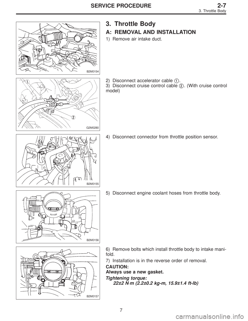
3. Throttle Body
A: REMOVAL AND INSTALLATION
1) Remove air intake duct.
G2M0280
2) Disconnect accelerator cable�1.
3) Disconnect cruise control cable�
2. (With cruise control
model)
B2M0155
4) Disconnect connector from throttle position sensor.
B2M0156
5) Disconnect engine coolant hoses from throttle body.
B2M0157
6) Remove bolts which install throttle body to intake mani-
fold.
7) Installation is in the reverse order of removal.
CAUTION:
Always use a new gasket.
Tightening torque:
22±2 N⋅m (2.2±0.2 kg-m, 15.9±1.4 ft-lb)
7
2-7SERVICE PROCEDURE
3. Throttle Body
Page 531 of 2890
B2M0157
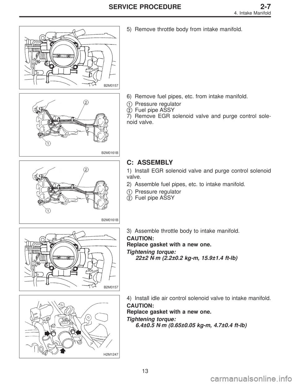
5) Remove throttle body from intake manifold.
B2M0161B
6) Remove fuel pipes, etc. from intake manifold.
�
1Pressure regulator
�
2Fuel pipe ASSY
7) Remove EGR solenoid valve and purge control sole-
noid valve.
B2M0161B
C: ASSEMBLY
1) Install EGR solenoid valve and purge control solenoid
valve.
2) Assemble fuel pipes, etc. to intake manifold.
�
1Pressure regulator
�
2Fuel pipe ASSY
B2M0157
3) Assemble throttle body to intake manifold.
CAUTION:
Replace gasket with a new one.
Tightening torque:
22±2 N⋅m (2.2±0.2 kg-m, 15.9±1.4 ft-lb)
H2M1247
4) Install idle air control solenoid valve to intake manifold.
CAUTION:
Replace gasket with a new one.
Tightening torque:
6.4±0.5 N⋅m (0.65±0.05 kg-m, 4.7±0.4 ft-lb)
13
2-7SERVICE PROCEDURE
4. Intake Manifold
Page 532 of 2890
B2M0347A
5) Install engine harness onto intake manifold.
6) Connect connectors to throttle position sensor, ignition
coil, fuel injectors, idle air control solenoid valve, purge
control solenoid valve and EGR solenoid valve.
�
1EGR solenoid valve
�
2Throttle position sensor
�
3Idle air control solenoid valve
�
4Purge control solenoid valve
�
5Harness band
B2M0757A
7) Connect engine ground terminal to intake manifold.
B2M0159
D: INSTALLATION
1) Install intake manifold onto cylinder heads.
CAUTION:
Always use new gaskets.
Tightening torque:
25±2 N⋅m (2.5±0.2 kg-m, 18.1±1.4 ft-lb)
G2M0296
2) Connect fuel hoses.
G2M0091
3) Connect connector to oil pressure switch.
14
2-7SERVICE PROCEDURE
4. Intake Manifold
Page 535 of 2890
B2M0334
15) Install power steering pump on bracket.
(1) Install power steering pump on bracket, and tighten
bolts.
Tightening torque:
20.1±2.5 N⋅m (2.05±0.25 kg-m, 14.8±1.8 ft-lb)
B2M0340
(2) Install power steering pipe bracket on right side
intake manifold.
G2M0286
(3) Install front side V-belt, and adjust it.
B2M0017
(4) Install V-belt cover.
G2M0280
16) Connect accelerator cable�1.
17) Connect cruise control cable�
2. (With cruise control
model)
17
2-7SERVICE PROCEDURE
4. Intake Manifold
Page 536 of 2890
B2M0154
18) Install air cleaner element, air cleaner upper cover and
air intake duct.
19) Connect connector to mass air flow sensor.
B2M0154
5. Engine Coolant Temperature Sensor
A: REMOVAL AND INSTALLATION
1) Remove air intake duct.
G2M0407
2) Disconnect connector from engine coolant temperature
sensor.
3) Remove engine coolant temperature sensor.
G2M0407
4) Installation is in the reverse order of removal.
Tightening torque:
25±3 N⋅m (2.5±0.3 kg-m, 18.1±2.2 ft-lb)
G2M0408
6. Crankshaft Position Sensor
A: REMOVAL AND INSTALLATION
1) Remove bolt which install crankshaft position sensor to
cylinder block.
18
2-7SERVICE PROCEDURE
4. Intake Manifold - 6. Crankshaft Position Sensor
Page 537 of 2890
G2M0409
2) Remove crankshaft position sensor, and disconnect
connector from it.
G2M0408
3) Installation is in the reverse order of removal.
Tightening torque:
6.4±0.5 N⋅m (0.65±0.05 kg-m, 4.7±0.4 ft-lb)
B2M0154
7. Front Oxygen Sensor
A: REMOVAL
1) Remove air intake duct.
G2M0544
2) Disconnect connector from front oxygen sensor.
3) Lift-up the vehicle.
4) Apply SUBARU CRC or its equivalent to threaded por-
tion of front oxygen sensor, and leave it for one minute or
more.
SUBARU CRC (Part No. 004301003)
19
2-7SERVICE PROCEDURE
6. Crankshaft Position Sensor - 7. Front Oxygen Sensor
Page 538 of 2890
G2M0411
5) Remove front oxygen sensor.
CAUTION:
When removing oxygen sensor, do not force oxygen
sensor especially when exhaust pipe is cold, other-
wise it will damage exhaust pipe.
G2M0412
B: INSTALLATION
1) Before installing front oxygen sensor, apply anti-seize
compound only to threaded portion of front oxygen sensor
to make the next removal easier.
Anti-seize compound:
SS-30 by JET LUBE
CAUTION:
Never apply anti-seize compound to protector of front
oxygen sensor.
G2M0411
2) Install front oxygen sensor.
Tightening torque:
21±3 N⋅m (2.1±0.3 kg-m, 15.2±2.2 ft-lb)
3) Lower the vehicle.
4) Connect connector of front oxygen sensor.
5) Install air intake duct.
20
2-7SERVICE PROCEDURE
7. Front Oxygen Sensor
 Remove air intake duct.
G2M0305
2) Disconnect connector from mass air flow sensor.
G2M0390
3) Remove air cleaner upper cover.
G2M0393
4)")
 Install engine harness onto intake manifold.
6) Connect connectors to throttle position sensor, ignition
coil, fuel injectors, idle air control solenoid valve, purge
control solenoid valve")
 Install power steering pump on bracket.
(1) Install power steering pump on bracket, and tighten
bolts.
Tightening torque:
20.1±2.5 N⋅m (2.05±0.25 kg-m, 14.8±1.8 ft-lb)
B2M0340
(2) Ins")
 Install air cleaner element, air cleaner upper cover and
air intake duct.
19) Connect connector to mass air flow sensor.
B2M0154
5. Engine Coolant Temperature Sensor
A: REMOVAL AND INSTALL")
 Remove crankshaft position sensor, and disconnect
connector from it.
G2M0408
3) Installation is in the reverse order of removal.
Tightening torque:
6.4±0.5 N⋅m (0.65±0.05 kg-m, 4.7±0.4")
 Remove front oxygen sensor.
CAUTION:
When removing oxygen sensor, do not force oxygen
sensor especially when exhaust pipe is cold, other-
wise it will damage exhaust pipe.
G2M0412
B: INSTAL")