Page 595 of 2890
 Install flywheel.
2) Install ST, and tighten the flywheel attaching bolts to the
specified torque.
ST 498497100 CRANKSHAFT STOPPER
Tightening torque:
72±3 N⋅m (")
B2M0331A
B2M0332A
C: INSTALLATION
1) Install flywheel.
2) Install ST, and tighten the flywheel attaching bolts to the
specified torque.
ST 498497100 CRANKSHAFT STOPPER
Tightening torque:
72±3 N⋅m (7.3±0.3 kg-m, 52.8±2.2 ft-lb)
NOTE:
Tighten flywheel installing bolts gradually. Each bolt should
be tightened to the specified torque in a crisscross fashion.
G2M0253
3) Insert ST into the clutch disc and install them on the
flywheel by inserting the ST end into the pilot bearing.
ST 499747100 CLUTCH DISC GUIDE
G2M0254
4) Install clutch cover on flywheel and tighten bolts to the
specified torque.
NOTE:
�When installing the clutch cover on the flywheel, position
the clutch cover so that there is a gap of 120°or more
between“0”marks on the flywheel and clutch cover. (“0”
marks indicate the directions of residual unbalance.)
�Note the front and rear of the clutch disc when installing.
�Tighten clutch cover installing bolts gradually. Each bolt
should be tightened to the specified torque in a crisscross
fashion.
Tightening torque:
15.7±1.5 N⋅m (1.6±0.15 kg-m, 11.6±1.1 ft-lb)
5) Remove ST.
ST 499747100 CLUTCH DISC GUIDE
10
2-10SERVICE PROCEDURE
4. Clutch Disc and Cover
Page 596 of 2890

G2M0213
C: INSTALLATION
Installation is in the reverse order of removal.
CAUTION:
�Replace gasket with a new one.
�When installing engine coolant pump, tighten bolts
in two stages in numerical sequence as shown in fig-
ure.
Tightening torque:
10
+4
�0N⋅m (1.0+0.4
�0kg-m, 7.2+2.9
�0ft-lb)
G2M0214
3. Thermostat
A: REMOVAL AND INSTALLATION
1) Drain engine coolant.
Set container under the vehicle, and remove drain cock
from radiator.
2) Disconnect radiator outlet hose from thermostat cover.
3) Remove thermostat cover and gasket, and pull out the
thermostat.
G2M0227
4) Install the thermostat in the intake manifold, and install
the thermostat cover together with a gasket.
CAUTION:
�When reinstalling the thermostat, use a new gasket.
�The thermostat must be installed with the jiggle pin
upward.
�In this time, set the jiggle pin of thermostat for front
side.
G2M0215
B: INSPECTION
Replace the thermostat if the valve does not close com-
pletely at an ambient temperature or if the following test
shows unsatisfactory results.
Immerse the thermostat and a thermometer in water. Raise
water temperature gradually, and measure the temperature
and valve lift when the valve begins to open and when the
valve is fully opened. During the test, agitate the water for
even temperature distribution. The measurement should
be to the specification.
Starts to open:
76.0—80.0°C (169—176°F)
Fully opens:
91°C (196°F)
12
2-5SERVICE PROCEDURE
2. Engine Coolant Pump - 3. Thermostat
Page 604 of 2890
B2M0138
5) Disconnect heater inlet hose.
B2M0139
6) Disconnect radiator inlet hose from engine coolant pipe.
B2M0141
7) Remove bolts which install engine coolant pipe on cyl-
inder block.
B2M0141
B: INSTALLATION
1) Install engine coolant pipe on cylinder block.
Tightening torque:
6.4±0.5 N⋅m (0.65±0.05 kg-m, 4.7±0.4 ft-lb)
CAUTION:
Use a new O-ring.
B2M0139
2) Connect radiator inlet hose.
18
2-5SERVICE PROCEDURE
7. Engine Coolant Pipe
Page 622 of 2890

�
2Intake manifold gasket RH
(2200 cc model)
�
3Intake manifold gasket LH
(2500 cc model)
�
4Intake manifold gasket RH
(2500 cc")
1. Intake Manifold
B2M0739A
�1Intake manifold gasket LH
(2200 cc model)
�
2Intake manifold gasket RH
(2200 cc model)
�
3Intake manifold gasket LH
(2500 cc model)
�
4Intake manifold gasket RH
(2500 cc model)
�
5Fuel injector pipe insulator
�
6Fuel injector pipe
�
7O-ring A
�
8O-ring B
�
9Fuel injector
�
10Insulator
�
11Fuel injector cap
�
12Plate
�
13Sealing�
14Gasket
�
15Engine coolant hose B
�
16Air by-pass hose
�
17Idle air control solenoid valve
�
18Engine coolant hose A
�
19Nipple (AT model)
�
20Plug
�
21PCV valve
�
22Purge control solenoid valve
�
23Nipple
�
24BPT
�
25BPT holder bracket
�
26Back pressure hose
�
27EGR vacuum hose A
�
28EGR vacuum pipe
�
29EGR vacuum hose C
�
30EGR valve�
31Gasket
�
32EGR vacuum hose B
�
33EGR solenoid valve
�
34EGR pipe
�
35Collar
�
36Intake manifold
Tightening torque: N⋅m (kg-m, ft-lb)
T1: 3.4±0.5 (0.35±0.05, 2.5±0.4)
T2: 6.4±0.5 (0.65±0.05, 4.7±0.4)
T3: 16±1.5 (1.6±0.15, 11.6±1.1)
T4: 19±1 (1.9±0.1, 13.7±0.7)
T5: 19±1.5 (1.9±0.15, 13.7±1.1)
T6: 23±3 (2.3±0.3, 16.6±2.2)
T7: 25±2 (2.5±0.2, 18.1±1.4)
T8: 34±2 (3.5±0.2, 25.3±1.4)
2
2-7COMPONENT PARTS
1. Intake Manifold
Page 623 of 2890
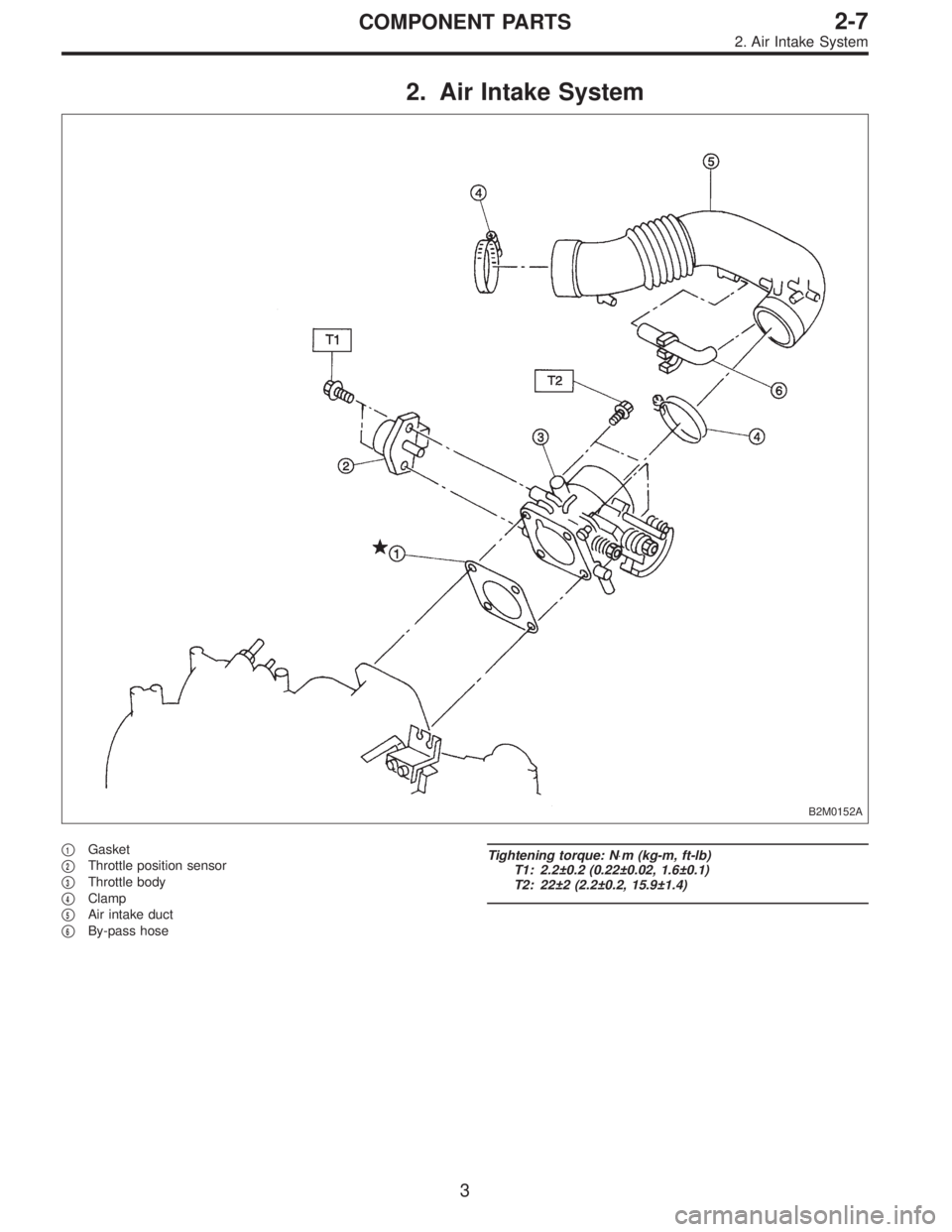
2. Air Intake System
B2M0152A
�1Gasket
�
2Throttle position sensor
�
3Throttle body
�
4Clamp
�
5Air intake duct
�
6By-pass hose
Tightening torque: N⋅m (kg-m, ft-lb)
T1: 2.2±0.2 (0.22±0.02, 1.6±0.1)
T2: 22±2 (2.2±0.2, 15.9±1.4)
3
2-7COMPONENT PARTS
2. Air Intake System
Page 624 of 2890
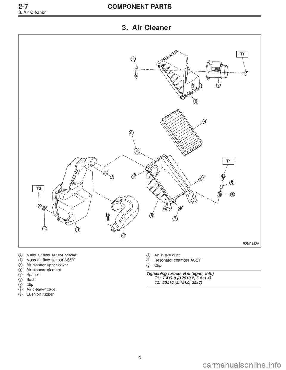
3. Air Cleaner
B2M0153A
�1Mass air flow sensor bracket
�
2Mass air flow sensor ASSY
�
3Air cleaner upper cover
�
4Air cleaner element
�
5Spacer
�
6Bush
�
7Clip
�
8Air cleaner case
�
9Cushion rubber�
10Air intake duct
�
11Resonator chamber ASSY
�
12Clip
Tightening torque: N⋅m (kg-m, ft-lb)
T1: 7.4±2.0 (0.75±0.2, 5.4±1.4)
T2: 33±10 (3.4±1.0, 25±7)
4
2-7COMPONENT PARTS
3. Air Cleaner
Page 626 of 2890
B2M0154
2. Mass Air Flow Sensor
A: REMOVAL AND INSTALLATION
1) Remove air intake duct.
G2M0305
2) Disconnect connector from mass air flow sensor.
G2M0390
3) Remove air cleaner upper cover.
G2M0393
4) Remove mass air flow sensor from air cleaner upper
cover.
5) Installation is in the reverse order of removal.
Tightening torque:
7.4±2.0 N⋅m (0.75±0.2 kg-m, 5.4±1.4 ft-lb)
6
2-7SERVICE PROCEDURE
2. Mass Air Flow Sensor
Page 627 of 2890
B2M0154
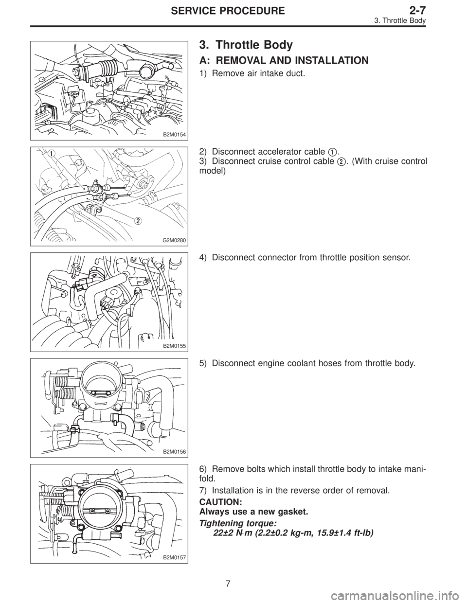
3. Throttle Body
A: REMOVAL AND INSTALLATION
1) Remove air intake duct.
G2M0280
2) Disconnect accelerator cable�1.
3) Disconnect cruise control cable�
2. (With cruise control
model)
B2M0155
4) Disconnect connector from throttle position sensor.
B2M0156
5) Disconnect engine coolant hoses from throttle body.
B2M0157
6) Remove bolts which install throttle body to intake mani-
fold.
7) Installation is in the reverse order of removal.
CAUTION:
Always use a new gasket.
Tightening torque:
22±2 N⋅m (2.2±0.2 kg-m, 15.9±1.4 ft-lb)
7
2-7SERVICE PROCEDURE
3. Throttle Body
 Disconnect heater inlet hose.
B2M0139
6) Disconnect radiator inlet hose from engine coolant pipe.
B2M0141
7) Remove bolts which install engine coolant pipe on cyl-
inder block.
B2M0141
B: I")
 Remove air intake duct.
G2M0305
2) Disconnect connector from mass air flow sensor.
G2M0390
3) Remove air cleaner upper cover.
G2M0393
4)")