Page 679 of 2890
C: INSTALLATION
CAUTION:
�If fuel hoses are damaged at the connecting portion,
replace it with a new one.
�If clamps are badly damaged, replace with new ones.
G2M0347
1) Installation is in the reverse order of removal.
2) Tighten hose clamp screws.
Tightening torque:
1.0
+0.5
�0N⋅m (0.1+0.05
�0kg-m, 0.7+0.4
�0ft-lb)
B2M0048A
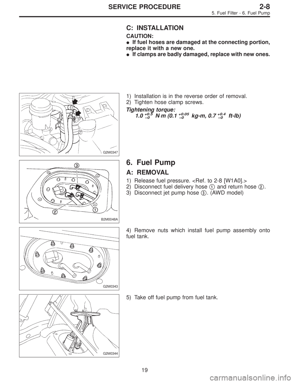
6. Fuel Pump
A: REMOVAL
1) Release fuel pressure.
2) Disconnect fuel delivery hose�
1and return hose�2.
3) Disconnect jet pump hose�
3. (AWD model)
G2M0343
4) Remove nuts which install fuel pump assembly onto
fuel tank.
G2M0344
5) Take off fuel pump from fuel tank.
19
2-8SERVICE PROCEDURE
5. Fuel Filter - 6. Fuel Pump
Page 680 of 2890
C: INSTALLATION
CAUTION:
�If fuel hoses are damaged at the connecting portion,
replace it with a new one.
�If clamps are badly damaged, replace with new ones.
G2M0347
1) Installation is in the reverse order of removal.
2) Tighten hose clamp screws.
Tightening torque:
1.0
+0.5
�0N⋅m (0.1+0.05
�0kg-m, 0.7+0.4
�0ft-lb)
B2M0048A
6. Fuel Pump
A: REMOVAL
1) Release fuel pressure.
2) Disconnect fuel delivery hose�
1and return hose�2.
3) Disconnect jet pump hose�
3. (AWD model)
G2M0343
4) Remove nuts which install fuel pump assembly onto
fuel tank.
G2M0344
5) Take off fuel pump from fuel tank.
19
2-8SERVICE PROCEDURE
5. Fuel Filter - 6. Fuel Pump
Page 681 of 2890

G2M0366
B: INSPECTION
Connect lead harness to connector terminal of fuel pump,
and apply battery power supply to check whether the pump
operate.
WARNING:
�Wipe off the fuel completely.
�Keep battery as far apart from fuel pump as pos-
sible.
�Be sure to turn the battery supply ON and OFF on
the battery side.
�Do not run fuel pump for a long time under non-load
condition.
G2M0346
C: INSTALLATION
Installation is in the reverse order of removal. Do the fol-
lowing:
(1) Always use new gaskets.
(2) Ensure sealing portion is free from fuel or foreign
particles before installation.
(3) Tighten nuts in numerical sequence shown in Fig-
ure to specified torque.
Tightening torque:
4.4±1.5 N⋅m (0.45±0.15 kg-m, 3.3±1.1 ft-lb)
B2M0048A
7. Fuel Meter Unit
A: REMOVAL
NOTE:
Fuel meter unit is built in fuel pump assembly.
1) Release fuel pressure.
2) Disconnect fuel delivery hose�
1and return hose�2.
3) Disconnect jet pump hose�
3. (AWD model)
20
2-8SERVICE PROCEDURE
6. Fuel Pump - 7. Fuel Meter Unit
Page 682 of 2890

G2M0366
B: INSPECTION
Connect lead harness to connector terminal of fuel pump,
and apply battery power supply to check whether the pump
operate.
WARNING:
�Wipe off the fuel completely.
�Keep battery as far apart from fuel pump as pos-
sible.
�Be sure to turn the battery supply ON and OFF on
the battery side.
�Do not run fuel pump for a long time under non-load
condition.
G2M0346
C: INSTALLATION
Installation is in the reverse order of removal. Do the fol-
lowing:
(1) Always use new gaskets.
(2) Ensure sealing portion is free from fuel or foreign
particles before installation.
(3) Tighten nuts in numerical sequence shown in Fig-
ure to specified torque.
Tightening torque:
4.4±1.5 N⋅m (0.45±0.15 kg-m, 3.3±1.1 ft-lb)
B2M0048A
7. Fuel Meter Unit
A: REMOVAL
NOTE:
Fuel meter unit is built in fuel pump assembly.
1) Release fuel pressure.
2) Disconnect fuel delivery hose�
1and return hose�2.
3) Disconnect jet pump hose�
3. (AWD model)
20
2-8SERVICE PROCEDURE
6. Fuel Pump - 7. Fuel Meter Unit
Page 683 of 2890
G2M0344
4) Remove nuts which install fuel pump assembly onto
fuel tank.
5) Take off fuel pump assembly.
G2M0346
B: INSTALLATION
Installation is in the reverse order of removal. Do the fol-
lowing:
(1) Always use new gaskets.
(2) Ensure sealing portion is free from fuel or foreign
particles before installation.
(3) Tighten nuts in numerical sequence shown in Fig-
ure to specified torque.
Tightening torque:
4.4±1.5 N⋅m (0.45±0.15 kg-m, 3.3±1.1 ft-lb)
21
2-8SERVICE PROCEDURE
7. Fuel Meter Unit
Page 689 of 2890
G2M0864
4) Disconnect connector from fuel sub meter.
5) Disconnect jet pump hose.
G2M0865
6) Remove fuel sub meter unit.
G2M0866
7) Installation is in the reverse order of removal procedure.
Tightening torque:
T: 3—6N⋅m (0.3—0.6 kg-m, 2.2—4.3 ft-lb)
G2M0356
11. Fuel Cut Valve (AWD model only)
A: REMOVAL AND INSTALLATION
1) Remove fuel tank.
G2M0867
2) Disconnect evaporation hose from fuel cut valve.
3) Remove fuel cut valve.
4) Installation is in the reverse order of removal procedure.
Tightening torque:
4.4±1.5 N⋅m (0.45±0.15 kg-m, 3.3±1.1 ft-lb)
26
2-8SERVICE PROCEDURE
10. Fuel Sub Meter Unit (AWD model only) - 11. Fuel Cut Valve (AWD model only)
Page 690 of 2890
G2M0864
4) Disconnect connector from fuel sub meter.
5) Disconnect jet pump hose.
G2M0865
6) Remove fuel sub meter unit.
G2M0866
7) Installation is in the reverse order of removal procedure.
Tightening torque:
T: 3—6N⋅m (0.3—0.6 kg-m, 2.2—4.3 ft-lb)
G2M0356
11. Fuel Cut Valve (AWD model only)
A: REMOVAL AND INSTALLATION
1) Remove fuel tank.
G2M0867
2) Disconnect evaporation hose from fuel cut valve.
3) Remove fuel cut valve.
4) Installation is in the reverse order of removal procedure.
Tightening torque:
4.4±1.5 N⋅m (0.45±0.15 kg-m, 3.3±1.1 ft-lb)
26
2-8SERVICE PROCEDURE
10. Fuel Sub Meter Unit (AWD model only) - 11. Fuel Cut Valve (AWD model only)
Page 692 of 2890
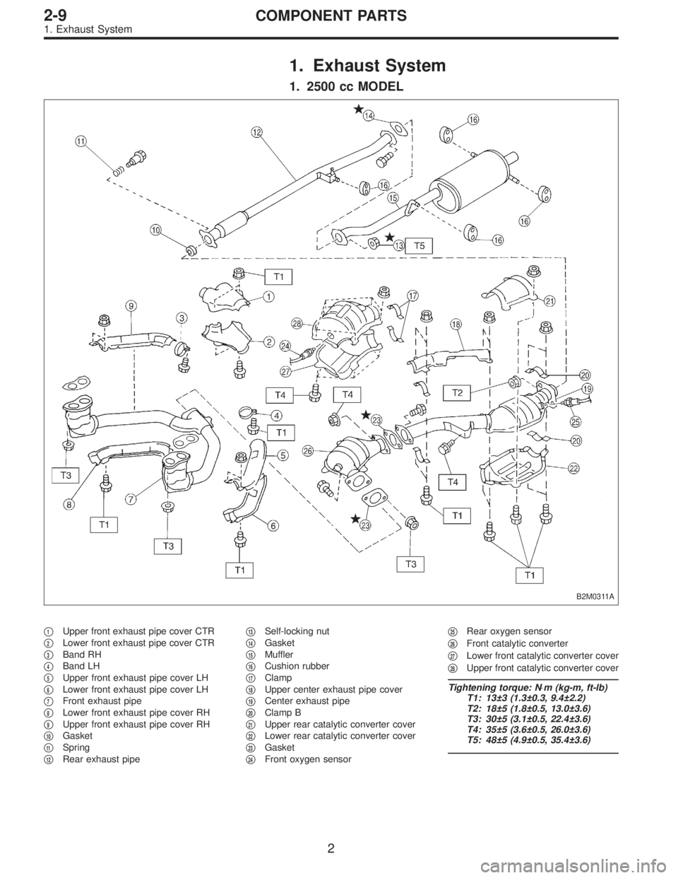
1. Exhaust System
1. 2500 cc MODEL
B2M0311A
�1Upper front exhaust pipe cover CTR
�
2Lower front exhaust pipe cover CTR
�
3Band RH
�
4Band LH
�
5Upper front exhaust pipe cover LH
�
6Lower front exhaust pipe cover LH
�
7Front exhaust pipe
�
8Lower front exhaust pipe cover RH
�
9Upper front exhaust pipe cover RH
�
10Gasket
�
11Spring
�
12Rear exhaust pipe�
13Self-locking nut
�
14Gasket
�
15Muffler
�
16Cushion rubber
�
17Clamp
�
18Upper center exhaust pipe cover
�
19Center exhaust pipe
�
20Clamp B
�
21Upper rear catalytic converter cover
�
22Lower rear catalytic converter cover
�
23Gasket
�
24Front oxygen sensor�
25Rear oxygen sensor
�
26Front catalytic converter
�
27Lower front catalytic converter cover
�
28Upper front catalytic converter cover
Tightening torque: N⋅m (kg-m, ft-lb)
T1: 13±3 (1.3±0.3, 9.4±2.2)
T2: 18±5 (1.8±0.5, 13.0±3.6)
T3: 30±5 (3.1±0.5, 22.4±3.6)
T4: 35±5 (3.6±0.5, 26.0±3.6)
T5: 48±5 (4.9±0.5, 35.4±3.6)
2
2-9COMPONENT PARTS
1. Exhaust System

 Remove nuts which install fuel pump assembly onto
fuel tank.
5) Take off fuel pump assembly.
G2M0346
B: INSTALLATION
Installation is in the reverse order of removal. Do the fol-
lowing:
(1)")
 Disconnect connector from fuel sub meter.
5) Disconnect jet pump hose.
G2M0865
6) Remove fuel sub meter unit.
G2M0866
7) Installation is in the reverse order of removal procedure.
Tightenin")
 Disconnect connector from fuel sub meter.
5) Disconnect jet pump hose.
G2M0865
6) Remove fuel sub meter unit.
G2M0866
7) Installation is in the reverse order of removal procedure.
Tightenin")