Page 693 of 2890

2. 2200 cc MODEL
B2M0723A
�1Upper front exhaust pipe cover CTR
�
2Lower front exhaust pipe cover CTR
�
3Band RH
�
4Band LH
�
5Upper front exhaust pipe cover LH
�
6Lower front exhaust pipe cover LH
�
7Front exhaust pipe
�
8Lower front exhaust pipe cover RH
�
9Upper front exhaust pipe cover RH
�
10Gasket
�
11Spring
�
12Rear exhaust pipe
�
13Self-locking nut�
14Gasket
�
15Muffler
�
16Cushion rubber
�
17Clamp
�
18Upper center exhaust pipe cover
�
19Center exhaust pipe
�
20Clamp B
�
21Upper rear catalytic converter cover
�
22Lower rear catalytic converter cover
�
23Gasket
�
24Front oxygen sensor
�
25Rear oxygen sensor (California 2200
cc model)�
26Rear oxygen sensor (Except Califor-
nia 2200 cc model)
�
27Front catalytic converter
�
28Lower front catalytic converter cover
�
29Upper front catalytic converter cover
Tightening torque: N⋅m (kg-m, ft-lb)
T1: 13±3 (1.3±0.3, 9.4±2.2)
T2: 18±5 (1.8±0.5, 13.0±3.6)
T3: 30±5 (3.1±0.5, 22.4±3.6)
T4: 35±5 (3.6±0.5, 26.0±3.6)
T5: 48±5 (4.9±0.5, 35.4±3.6)
3
2-9COMPONENT PARTS
1. Exhaust System
Page 695 of 2890
B2M0313
7) Remove front exhaust pipe and center exhaust pipe
from hanger bracket.
CAUTION:
Be careful not to pull down front exhaust pipe and
center exhaust pipe.
B2M0060
8) Separate front exhaust pipe from front catalytic con-
verter.
B2M0060
B: INSTALLATION
CAUTION:
Replace gaskets with new ones.
1) Install front catalytic converter to front exhaust pipe.
Tightening torque:
30±5 N⋅m (3.1±0.5 kg-m, 22.4±3.6 ft-lb)
B2M0313
2) Install front exhaust pipe and center exhaust pipe.
And temporarily tighten bolt which installs center exhaust
pipe to hanger bracket.
B2M0054
3) Tighten bolts which hold front exhaust pipe onto cylin-
der heads.
Tightening torque:
30±5 N⋅m (3.1±0.5 kg-m, 22.4±3.6 ft-lb)
5
2-9SERVICE PROCEDURE
1. Front Exhaust Pipe and Center Exhaust Pipe
Page 696 of 2890
B2M0055
4) Install center exhaust pipe to rear exhaust pipe.
Tightening torque:
18±5 N⋅m (1.8±0.5 kg-m, 13.0±3.6 ft-lb)
B2M0313
5) Tighten bolt which holds center exhaust pipe to hanger
bracket.
Tightening torque:
35±5 N⋅m (3.6±0.5 kg-m, 26.0±3.6 ft-lb)
B2M0312
6) Connect rear oxygen sensor connector. (Except Califor-
nia 2200 cc model)
B2M0725
7) Lower the vehicle.
8) Connect rear oxygen sensor connector. (California
2200 cc model)
B2M0724
9) Connect front oxygen sensor connector.
6
2-9SERVICE PROCEDURE
1. Front Exhaust Pipe and Center Exhaust Pipe
Page 697 of 2890
B2M0055
2. Rear Exhaust Pipe
A: REMOVAL
1) Separate rear exhaust pipe from center exhaust pipe.
B2M0061
2) Separate rear exhaust pipe from muffler.
CAUTION:
Be careful not to pull down rear exhaust pipe.
G2M0315
3) Remove rear exhaust pipe bracket from rubber cushion.
NOTE:
To facilitate removal, apply a coat of SUBARU CRC or
equivalent to pipe bracket in advance.
SUBARU CRC (Part No. 004301003)
G2M0315
B: INSTALLATION
CAUTION:
Replace gaskets with new ones.
1) Install rear exhaust pipe bracket to rubber cushion.
NOTE:
To facilitate installation, apply a coat of SUBARU CRC or
equivalent to mating area of rubber cushion in advance.
SUBARU CRC (Part No. 004301003)
B2M0061
2) Install rear exhaust pipe to muffler.
Tightening torque:
48±5 N⋅m (4.9±0.5 kg-m, 35.4±3.6 ft-lb)
7
2-9SERVICE PROCEDURE
2. Rear Exhaust Pipe
Page 698 of 2890
B2M0055
3) Install rear exhaust pipe to center exhaust pipe.
Tightening torque:
18±5 N⋅m (1.8±0.5 kg-m, 13.0±3.6 ft-lb)
8
2-9SERVICE PROCEDURE
2. Rear Exhaust Pipe
Page 699 of 2890
B2M0061
3. Muffler
A: REMOVAL AND INSTALLATION
1) Separate muffler from rear exhaust pipe.
B2M0062
2) Remove left and right rubber cushions.
CAUTION:
Be careful not to pull down muffler.
NOTE:
To facilitate removal, apply a coat of SUBARU CRC or
equivalent to mating area of rubber cushions in advance.
SUBARU CRC (Part No. 004301003)
B2M0063
3) Remove front rubber cushion, and detach muffler
assembly.
NOTE:
To facilitate removal, apply a coat of SUBARU CRC or
equivalent to mating area of rubber cushion in advance.
SUBARU CRC (Part No. 004301003)
B2M0061
4) Installation is in the reverse order of removal.
CAUTION:
Replace gasket with a new one.
Tightening torque:
48±5 N⋅m (4.9±0.5 kg-m, 35.4±3.6 ft-lb)
9
2-9SERVICE PROCEDURE
3. Muffler
Page 701 of 2890
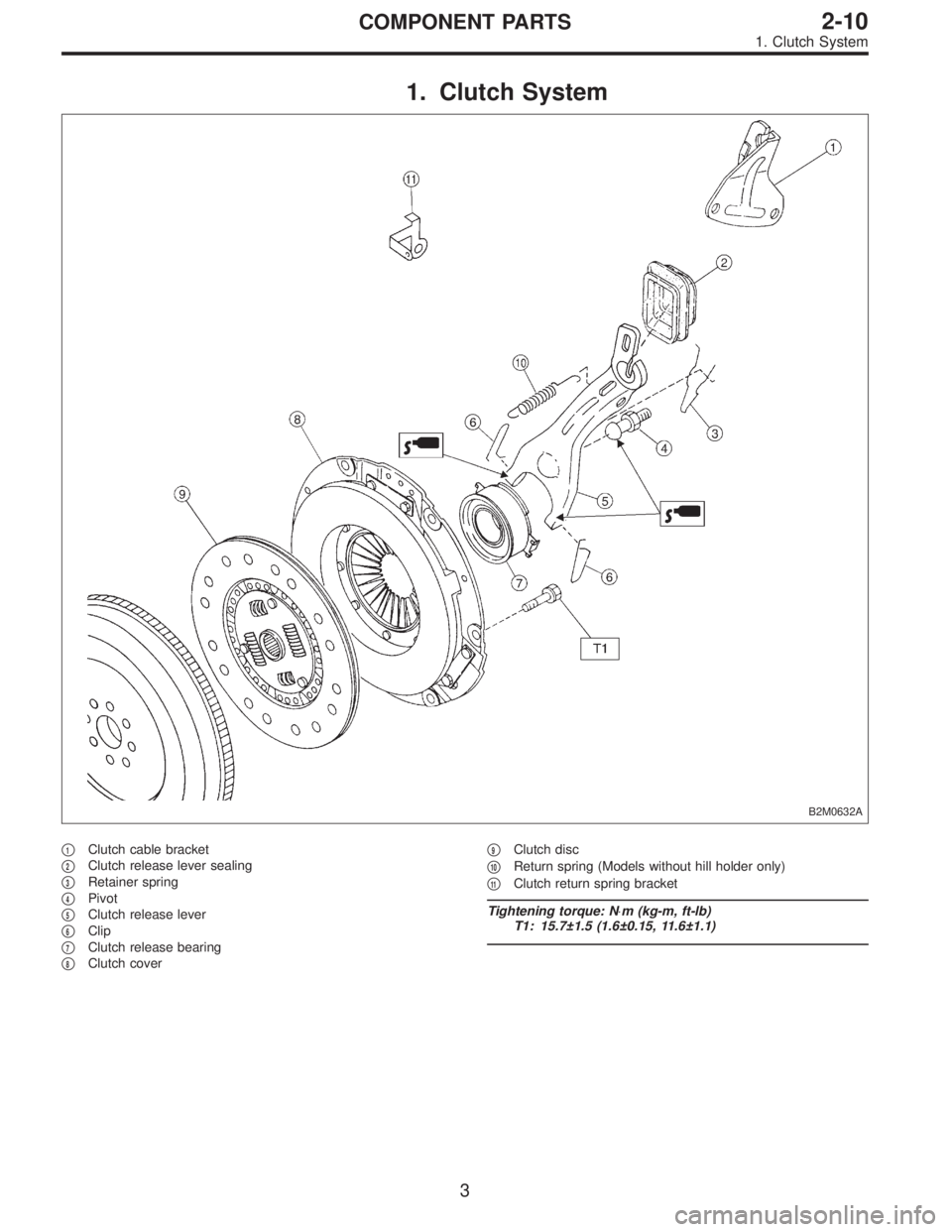
1. Clutch System
B2M0632A
�1Clutch cable bracket
�
2Clutch release lever sealing
�
3Retainer spring
�
4Pivot
�
5Clutch release lever
�
6Clip
�
7Clutch release bearing
�
8Clutch cover�
9Clutch disc
�
10Return spring (Models without hill holder only)
�
11Clutch return spring bracket
Tightening torque: N⋅m (kg-m, ft-lb)
T1: 15.7±1.5 (1.6±0.15, 11.6±1.1)
3
2-10COMPONENT PARTS
1. Clutch System
Page 711 of 2890
 Install flywheel.
2) Install ST, and tighten the flywheel attaching bolts to the
specified torque.
ST 498497100 CRANKSHAFT STOPPER
Tightening torque:
72±3 N⋅m (")
B2M0331A
B2M0332A
C: INSTALLATION
1) Install flywheel.
2) Install ST, and tighten the flywheel attaching bolts to the
specified torque.
ST 498497100 CRANKSHAFT STOPPER
Tightening torque:
72±3 N⋅m (7.3±0.3 kg-m, 52.8±2.2 ft-lb)
NOTE:
Tighten flywheel installing bolts gradually. Each bolt should
be tightened to the specified torque in a crisscross fashion.
G2M0253
3) Insert ST into the clutch disc and install them on the
flywheel by inserting the ST end into the pilot bearing.
ST 499747100 CLUTCH DISC GUIDE
G2M0254
4) Install clutch cover on flywheel and tighten bolts to the
specified torque.
NOTE:
�When installing the clutch cover on the flywheel, position
the clutch cover so that there is a gap of 120°or more
between“0”marks on the flywheel and clutch cover. (“0”
marks indicate the directions of residual unbalance.)
�Note the front and rear of the clutch disc when installing.
�Tighten clutch cover installing bolts gradually. Each bolt
should be tightened to the specified torque in a crisscross
fashion.
Tightening torque:
15.7±1.5 N⋅m (1.6±0.15 kg-m, 11.6±1.1 ft-lb)
5) Remove ST.
ST 499747100 CLUTCH DISC GUIDE
10
2-10SERVICE PROCEDURE
4. Clutch Disc and Cover
 Remove front exhaust pipe and center exhaust pipe
from hanger bracket.
CAUTION:
Be careful not to pull down front exhaust pipe and
center exhaust pipe.
B2M0060
8) Separate front exhaust pip")
 Install center exhaust pipe to rear exhaust pipe.
Tightening torque:
18±5 N⋅m (1.8±0.5 kg-m, 13.0±3.6 ft-lb)
B2M0313
5) Tighten bolt which holds center exhaust pipe to hanger
bracket.")
 Separate rear exhaust pipe from center exhaust pipe.
B2M0061
2) Separate rear exhaust pipe from muffler.
CAUTION:
Be careful not to pull down rear exhaust pi")
 Install rear exhaust pipe to center exhaust pipe.
Tightening torque:
18±5 N⋅m (1.8±0.5 kg-m, 13.0±3.6 ft-lb)
8
2-9SERVICE PROCEDURE
2. Rear Exhaust Pipe")
 Separate muffler from rear exhaust pipe.
B2M0062
2) Remove left and right rubber cushions.
CAUTION:
Be careful not to pull down muffler.
NOTE:
To faci")