Page 376 of 2890
H2M1707B
4) Installation of piston rings and oil ring
(1) Install oil ring spacer, upper rail and lower rail in this
order by hand. Then install second ring and top ring
with a piston ring expander.
(2) Position the top ring gap at A or B in the Figure.
(3) Position the second ring gap at 180°on the reverse
side for the top ring gap.
H2M1708B
(4) Position the upper rail gap at C or D in the Figure.
(5) Position the expander gap at 180°of the reverse
side for the upper rail gap.
(6) Position the lower rail gap at E or F in the Figure.
CAUTION:
�Ensure ring gaps do not face the same direction.
�Ensure ring gaps are not within the piston skirt area.
B2M1403A
5) Install circlip.
Install circlips in piston holes located opposite service
holes in cylinder block, when positioning all pistons in the
corresponding cylinders.
CAUTION:
Use new circlips.
NOTE:
Piston front mark“�”facer toward front of engine.
66
2-3SERVICE PROCEDURE
7. Cylinder Block
Page 421 of 2890
 Camshaft installation
Apply engine oil to cylinder head at camshaft bearing loca-
tion before installing camshaft. Install camshaft so that
rocker arm is close to or in contact with“base")
B2M0764A
1) Camshaft installation
Apply engine oil to cylinder head at camshaft bearing loca-
tion before installing camshaft. Install camshaft so that
rocker arm is close to or in contact with“base circle”of cam
lobe.
CAUTION:
�When camshafts are positioned as shown in figure,
camshafts need to be rotated at a minimum to align
with timing belt during installation.
�Right-hand camshaft need not be rotated when set
at position shown in figure.
Left-hand intake camshaft: Rotate 80°clockwise.
Left-hand exhaust camshaft: Rotate 45°counter-clock-
wise.
G2M0752
2) Camshaft cap installation
(1) Apply fluid packing sparingly to cap mating surface.
CAUTION:
Do not apply fluid packing excessively. Failure to do so
may cause excess packing to come out and flow
toward oil seal, resulting in oil leaks.
Fluid packing:
THREE BOND 1215 or equivalent
G2M0753
(2) Apply engine oil to cap bearing surface and install
cap on camshaft as shown by identification mark.
(3) Gradually tighten cap in at least two stages in the
numerical order shown in figure, and then tighten to
specified torque.
(4) Similarly, tighten cap on exhaust side.
After tightening cap, ensure camshaft rotates only
slightly while holding it at“base”circle.
G2M0754
3) Camshaft oil seal installation
Apply grease to new oil seal lips and press onto front end
of camshaft by using ST1 and ST2.
CAUTION:
Use a new oil seal.
ST1 499587100 OIL SEAL INSTALLER
ST2 499597000 OIL SEAL GUIDE
33
2-3bSERVICE PROCEDURE
3. Camshaft
Page 566 of 2890
 Remove right rear wheel.
4) Open fuel filler flap and remove filler cap.
5) Remove screws holding packing in place.
G2M0361
6) Lift-up the vehicle.
7) Remove fuel filler pipe protector.
G2M")
G2M0360
3) Remove right rear wheel.
4) Open fuel filler flap and remove filler cap.
5) Remove screws holding packing in place.
G2M0361
6) Lift-up the vehicle.
7) Remove fuel filler pipe protector.
G2M0353
8) Remove clip, and separate air vent hose from pipe.
9) Loosen clamp, and separate fuel filler hose from pipe.
�
1Fuel filler hose
�
2Air vent hose
10) Remove fuel filler pipe to under side of the vehicle.
G2M0364
B: INSTALLATION
1) Hold fuel filler flap open.
2) Set fuel saucer�
1with rubber packing�3, and insert fuel
filler pipe into hole from the inner side of apron.
3) Align holes in fuel filler pipe neck and set cup�
2, and
tighten screws.
NOTE:
If edges of rubber packing are folded toward the inside,
straighten it with a screwdriver.
G2M0353
4) Insert fuel filler hose approximately 25 to 30 mm (0.98
to 1.18 in) over the lower end of fuel filler pipe and tighten
clamp.
�
1Fuel filler hose
�
2Air vent hose
CAUTION:
Do not allow clips to touch air vent hose and rear sus-
pension crossmember.
17
2-8SERVICE PROCEDURE
4. Fuel Filler Pipe
Page 676 of 2890
 Remove right rear wheel.
4) Open fuel filler flap and remove filler cap.
5) Remove screws holding packing in place.
G2M0361
6) Lift-up the vehicle.
7) Remove fuel filler pipe protector.
G2M")
G2M0360
3) Remove right rear wheel.
4) Open fuel filler flap and remove filler cap.
5) Remove screws holding packing in place.
G2M0361
6) Lift-up the vehicle.
7) Remove fuel filler pipe protector.
G2M0353
8) Remove clip, and separate air vent hose from pipe.
9) Loosen clamp, and separate fuel filler hose from pipe.
�
1Fuel filler hose
�
2Air vent hose
10) Remove fuel filler pipe to under side of the vehicle.
G2M0364
B: INSTALLATION
1) Hold fuel filler flap open.
2) Set fuel saucer�
1with rubber packing�3, and insert fuel
filler pipe into hole from the inner side of apron.
3) Align holes in fuel filler pipe neck and set cup�
2, and
tighten screws.
NOTE:
If edges of rubber packing are folded toward the inside,
straighten it with a screwdriver.
G2M0353
4) Insert fuel filler hose approximately 25 to 30 mm (0.98
to 1.18 in) over the lower end of fuel filler pipe and tighten
clamp.
�
1Fuel filler hose
�
2Air vent hose
CAUTION:
Do not allow clips to touch air vent hose and rear sus-
pension crossmember.
17
2-8SERVICE PROCEDURE
4. Fuel Filler Pipe
Page 748 of 2890
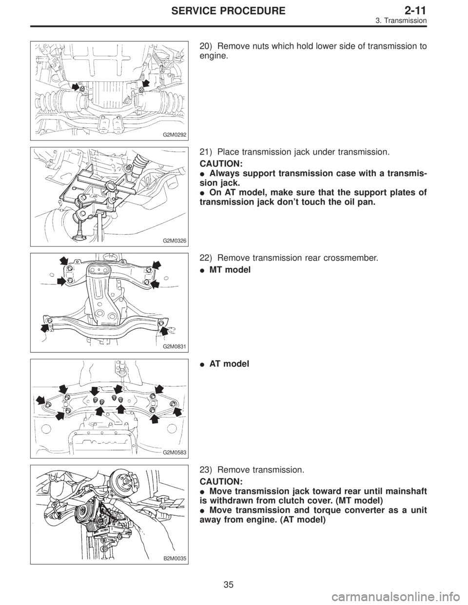
G2M0292
20) Remove nuts which hold lower side of transmission to
engine.
G2M0326
21) Place transmission jack under transmission.
CAUTION:
�Always support transmission case with a transmis-
sion jack.
�On AT model, make sure that the support plates of
transmission jack don’t touch the oil pan.
G2M0831
22) Remove transmission rear crossmember.
�MT model
G2M0583
�AT model
B2M0035
23) Remove transmission.
CAUTION:
�Move transmission jack toward rear until mainshaft
is withdrawn from clutch cover. (MT model)
�Move transmission and torque converter as a unit
away from engine. (AT model)
35
2-11SERVICE PROCEDURE
3. Transmission
Page 781 of 2890
 Assembly of reverse check sleeve
(1) Install reverse accent shaft�
F, check cam�D, re")
B3M0043A
2. TRANSFER CASE
Assembly of transfer case is in the reverse order of disas-
sembly. Do the following:
1) Assembly of reverse check sleeve
(1) Install reverse accent shaft�
F, check cam�D, return
spring�
Eand check spring�Conto reverse check
sleeve.
NOTE:
Be sure the bent section of reverse check spring is posi-
tioned in the groove in check cam.
(2) Hook the bent section of reverse check spring over
reverse check plate�
B.
(3) Rotate cam so that the protrusion of reverse check
cam is at the opening in plate.
(4) With cam held in that position, install plate onto
reverse check sleeve and hold with snap ring�
A(Inner-
28).
(5) Position O-ring�
G(35.4 x 1.5) in groove in sleeve.
B3M0048A
CAUTION:
�Make sure the cutout section of reverse accent shaft
is aligned with the opening in reverse check sleeve.
�Spin cam by hand for smooth rotation.
If it does not return properly, replace reverse check
spring.
�Move cam and shaft all the way toward plate and
release.
If cam does not return properly, replace reverse check
spring; if shaft does not, check for scratches on the
inner surface of sleeve. If sleeve is in good order,
replace spring.
�Select a suitable reverse accent shaft and reverse
check plate by referring to “Neutral Position Adjust-
ment.”
25
3-1SERVICE PROCEDURE
2. Transfer Case and Extension (AWD Model)
Page 784 of 2890

T1: 15.7±1.5 (1.6±0.15, 11.6±1.1)
T2: 19.6±1.5 (2.00±0.15, 14.5±1.1)
T3: 24.5±2.0 (2.50±0.20, 18.1±1.4)
1) Install transfer cas")
D: INSTALLATION
B3M0053A
Tightening torque: N⋅m (kg-m, ft-lb)
T1: 15.7±1.5 (1.6±0.15, 11.6±1.1)
T2: 19.6±1.5 (2.00±0.15, 14.5±1.1)
T3: 24.5±2.0 (2.50±0.20, 18.1±1.4)
1) Install transfer case�2with extension assembly�1.
2) Secure selector arm to shifter arm with shifter fork
screw�
3. Shifter arm should be caught by pawl of rod.
Selector arm must be engaged with reverse check sleeve
assembly.
3) Adjustment of neutral position
(1) Shift gear into 3rd gear position.
(2) Shifter arm turns lightly toward the 1st/2nd gear
side but heavily toward the reverse gear side because
of the function of the return spring, until arm contacts
the stopper.
(3) Make adjustment so that the heavy stroke (reverse
side) is a little more than the light stroke (1st/2nd side).
(4) To adjust, remove bolts holding reverse check
sleeve assembly�
4to the case, move sleeve assem-
bly outward, and place adjustment shim (0 to 1 ea.)
between sleeve assembly and case to adjust the clear-
ance.
28
3-1SERVICE PROCEDURE
2. Transfer Case and Extension (AWD Model)
Page 787 of 2890
 Assembly of rear case is in the reverse order of disas-
sembly.
G3M0952
Tightening torque: N⋅m (kg-m, ft-lb)
T1: 6.4±0.5 (0.65±0.05, 4.7±0.4)
T2: 10±1 (1.0±0.1, 7.2±0.7)
T3: 25�")
B: ASSEMBLY
1) Assembly of rear case is in the reverse order of disas-
sembly.
G3M0952
Tightening torque: N⋅m (kg-m, ft-lb)
T1: 6.4±0.5 (0.65±0.05, 4.7±0.4)
T2: 10±1 (1.0±0.1, 7.2±0.7)
T3: 25±5 (2.5±0.5, 18.1±3.6)
2) Installation of shifter arm�6
Install shifter arm into the partition from the front while
inserting selector arm into the opening in reverse check
sleeve. Pass shaft through hole in selector arm until its end
comes out of the rear of transmission case assembly.
CAUTION:
Apply a coat of gear oil to shifter arm. Also make sure
oil seal is positioned properly.
3) Adjustment of neutral position
NOTE:
After assembling and installing rear case, adjust neutral
position.
(1) Shift gear into 3rd gear position.
(2) Shifter arm turns lightly toward the 1st/2nd gear
side but heavily toward the reverse gear side because
of the function of the return spring, until arm contacts
the stopper.
(3) Make adjustment so that the heavy stroke (reverse
side) is a little more than the light stroke (1st/2nd side).
(4) To adjust, remove bolts holding reverse check
sleeve assembly to the case, move sleeve assembly
outward, and place adjustment shim (0 to 1 ea.)
between sleeve assembly and case to adjust the clear-
ance.
31
3-1SERVICE PROCEDURE
3. Rear Case (FWD Model)
 Installation of piston rings and oil ring
(1) Install oil ring spacer, upper rail and lower rail in this
order by hand. Then install second ring and top ring
with a piston ring expander.
(")