Page 1258 of 2890

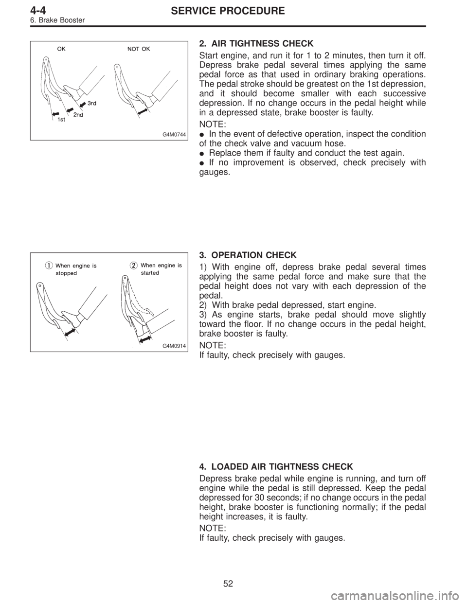
G4M0744
2. AIR TIGHTNESS CHECK
Start engine, and run it for 1 to 2 minutes, then turn it off.
Depress brake pedal several times applying the same
pedal force as that used in ordinary braking operations.
The pedal stroke should be greatest on the 1st depression,
and it should become smaller with each successive
depression. If no change occurs in the pedal height while
in a depressed state, brake booster is faulty.
NOTE:
�In the event of defective operation, inspect the condition
of the check valve and vacuum hose.
�Replace them if faulty and conduct the test again.
�If no improvement is observed, check precisely with
gauges.
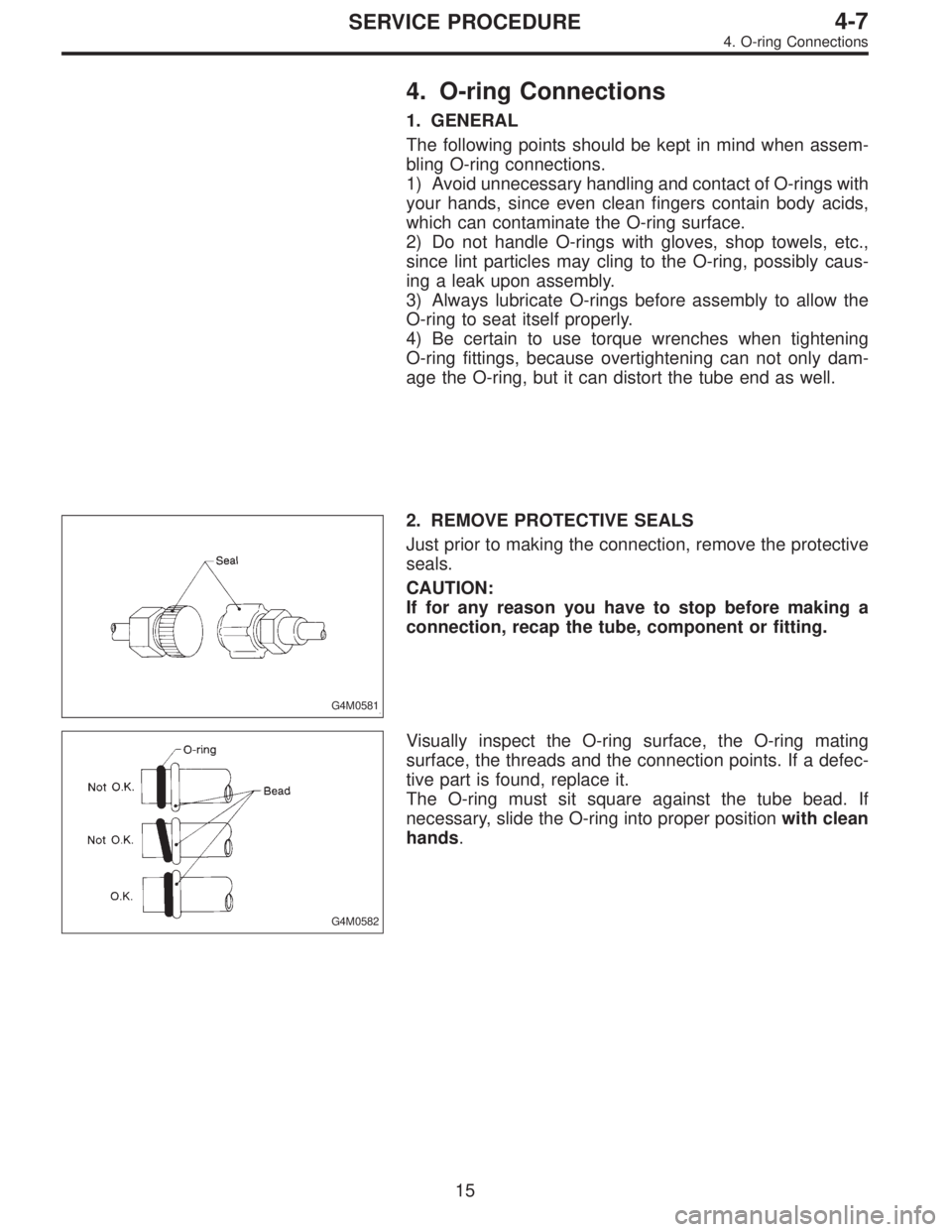
G4M0914
3. OPERATION CHECK
1) With engine off, depress brake pedal several times
applying the same pedal force and make sure that the
pedal height does not vary with each depression of the
pedal.
2) With brake pedal depressed, start engine.
3) As engine starts, brake pedal should move slightly
toward the floor. If no change occurs in the pedal height,
brake booster is faulty.
NOTE:
If faulty, check precisely with gauges.
4. LOADED AIR TIGHTNESS CHECK
Depress brake pedal while engine is running, and turn off
engine while the pedal is still depressed. Keep the pedal
depressed for 30 seconds; if no change occurs in the pedal
height, brake booster is functioning normally; if the pedal
height increases, it is faulty.
NOTE:
If faulty, check precisely with gauges.
52
4-4SERVICE PROCEDURE
6. Brake Booster
Page 1388 of 2890

4. O-ring Connections
1. GENERAL
The following points should be kept in mind when assem-
bling O-ring connections.
1) Avoid unnecessary handling and contact of O-rings with
your hands, since even clean fingers contain body acids,
which can contaminate the O-ring surface.
2) Do not handle O-rings with gloves, shop towels, etc.,
since lint particles may cling to the O-ring, possibly caus-
ing a leak upon assembly.
3) Always lubricate O-rings before assembly to allow the
O-ring to seat itself properly.
4) Be certain to use torque wrenches when tightening
O-ring fittings, because overtightening can not only dam-
age the O-ring, but it can distort the tube end as well.
G4M0581
2. REMOVE PROTECTIVE SEALS
Just prior to making the connection, remove the protective
seals.
CAUTION:
If for any reason you have to stop before making a
connection, recap the tube, component or fitting.
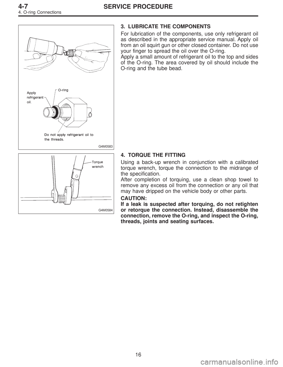
G4M0582
Visually inspect the O-ring surface, the O-ring mating
surface, the threads and the connection points. If a defec-
tive part is found, replace it.
The O-ring must sit square against the tube bead. If
necessary, slide the O-ring into proper positionwith clean
hands.
15
4-7SERVICE PROCEDURE
4. O-ring Connections
Page 1389 of 2890

G4M0583
3. LUBRICATE THE COMPONENTS
For lubrication of the components, use only refrigerant oil
as described in the appropriate service manual. Apply oil
from an oil squirt gun or other closed container. Do not use
your finger to spread the oil over the O-ring.
Apply a small amount of refrigerant oil to the top and sides
of the O-ring. The area covered by oil should include the
O-ring and the tube bead.
G4M0584
4. TORQUE THE FITTING
Using a back-up wrench in conjunction with a calibrated
torque wrench, torque the connection to the midrange of
the specification.
After completion of torquing, use a clean shop towel to
remove any excess oil from the connection or any oil that
may have dripped on the vehicle body or other parts.
CAUTION:
If a leak is suspected after torquing, do not retighten
or retorque the connection. Instead, disassemble the
connection, remove the O-ring, and inspect the O-ring,
threads, joints and seating surfaces.
16
4-7SERVICE PROCEDURE
4. O-ring Connections
Page 1396 of 2890

8. Leak Testing
The following points should be kept in mind when conduct-
ing a refrigerant leak test.
1) The A/C system to be tested must have an adequate
refrigerant charge to begin with.
2) The area where the leak test is conducted must be free
of wind and drafts, with still air being the ideal condition.
3) The atmosphere where the leak test is conducted must
be free of refrigerant contamination.
4) Operate the A/C system for approx. 10 minutes, then
turn the engine off an begin the leak test.
5) Refrigerant gas is heavier than air, therefore always
hold the probe below the connection being tested.
6) When checking for a leak along a length of hose or
tube, the leak detector probe must be moved slowly,
approx. 25 mm (1 in) per second making sure probe does
not come in contact with the component being tested.
7) When checking for a leak at a certain point, the leak
detector probe must be held at that point for at least 5
seconds.
G4M0609
1. CHECK THE SYSTEM PRESSURE
With gauges connected to the A/C system, operate the A/C
and confirm that the high side pressure is above 690 kPa
(7.03 kg/cm
2, 100 psi). If not, evacuate and charge the
system before leak checking (refer to evacuation and
charging sections).
2. CLEAN CONNECTIONS BEFORE TESTING
Before testing, use a clean shop towel to wipe off refriger-
ant oil, dirt, or foreign material from all of the connections
and components to be tested.
NOTE:
Since refrigerant oil absorbs refrigerant, excess oil on or
near a connection may falsely signal a leak.
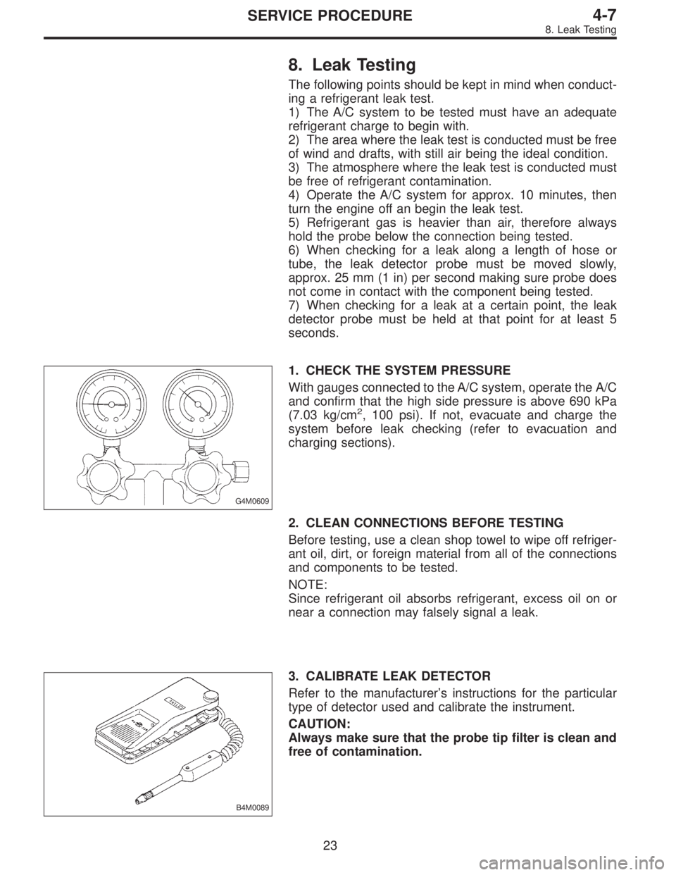
B4M0089
3. CALIBRATE LEAK DETECTOR
Refer to the manufacturer’s instructions for the particular
type of detector used and calibrate the instrument.
CAUTION:
Always make sure that the probe tip filter is clean and
free of contamination.
23
4-7SERVICE PROCEDURE
8. Leak Testing
Page 1481 of 2890
G5M0175
B: INSTALLATION
1) Installation is in the reverse order of removal.
2) Check for alignment of front fender with hood and front
door with front fender at all points. Adjust, if necessary.
B5M0287A
9. Mud Guard and Rear Arch
Protector
A: REMOVAL
SUPPLEMENTAL RESTRAINT SYSTEM“AIRBAG”
Airbag system wiring harness is routed near the mud
guard.
CAUTION:
�All Airbag system wiring harness and connectors
are colored yellow. Do not use electrical test equip-
ment on these circuits.
�Be careful not to damage Airbag system wiring har-
ness when servicing the mud guard.
B5M0288
1. MUD GUARD (EXCEPT OUTBACK WITH STEP
ROOF)
1) Jack-up vehicle to remove tire.
2) Remove screws and clips. Move mud guard toward the
center of the body and remove mud guard.
52
5-1SERVICE PROCEDURE
8. Front Fender - 9. Mud Guard and Rear Arch Protector
Page 1482 of 2890
G5M0175
B: INSTALLATION
1) Installation is in the reverse order of removal.
2) Check for alignment of front fender with hood and front
door with front fender at all points. Adjust, if necessary.
B5M0287A
9. Mud Guard and Rear Arch
Protector
A: REMOVAL
SUPPLEMENTAL RESTRAINT SYSTEM“AIRBAG”
Airbag system wiring harness is routed near the mud
guard.
CAUTION:
�All Airbag system wiring harness and connectors
are colored yellow. Do not use electrical test equip-
ment on these circuits.
�Be careful not to damage Airbag system wiring har-
ness when servicing the mud guard.
B5M0288
1. MUD GUARD (EXCEPT OUTBACK WITH STEP
ROOF)
1) Jack-up vehicle to remove tire.
2) Remove screws and clips. Move mud guard toward the
center of the body and remove mud guard.
52
5-1SERVICE PROCEDURE
8. Front Fender - 9. Mud Guard and Rear Arch Protector
Page 1483 of 2890
B5M0289
2. REAR ARCH PROTECTOR
Remove rear arch protector.
B5M0410
3. MUD GUARD (OUTBACK WITH STEP ROOF)
1) Jack-up vehicle to remove tire.
2) Remove screws and clips. Move mud guard toward the
center of the body and remove mud guard.
B: INSTALLATION
Installation is in the reverse order of removal.
CAUTION:
Only use new screws and clips.
B5M0290A
10. Cowl Panel
A: REMOVAL
1) Remove wiper arms.
2) Open front hood.
3) Remove cowl panel seal using a plier.
B5M0291
4) Lift cowl panel and detach it from clips attached to body
panel.
53
5-1SERVICE PROCEDURE
9. Mud Guard and Rear Arch Protector - 10. Cowl Panel
Page 1484 of 2890
B5M0289
2. REAR ARCH PROTECTOR
Remove rear arch protector.
B5M0410
3. MUD GUARD (OUTBACK WITH STEP ROOF)
1) Jack-up vehicle to remove tire.
2) Remove screws and clips. Move mud guard toward the
center of the body and remove mud guard.
B: INSTALLATION
Installation is in the reverse order of removal.
CAUTION:
Only use new screws and clips.
B5M0290A
10. Cowl Panel
A: REMOVAL
1) Remove wiper arms.
2) Open front hood.
3) Remove cowl panel seal using a plier.
B5M0291
4) Lift cowl panel and detach it from clips attached to body
panel.
53
5-1SERVICE PROCEDURE
9. Mud Guard and Rear Arch Protector - 10. Cowl Panel