Page 1148 of 2890
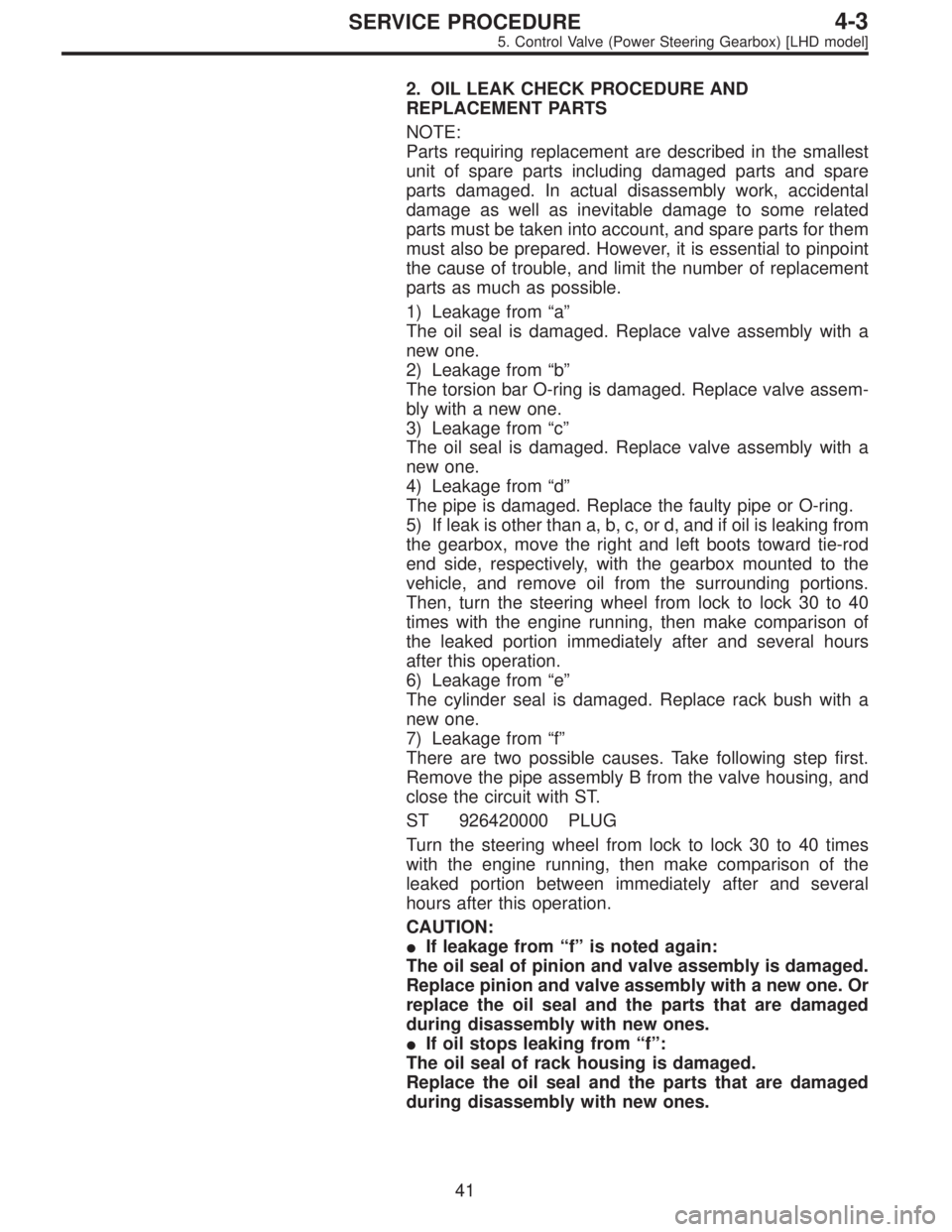
2. OIL LEAK CHECK PROCEDURE AND
REPLACEMENT PARTS
NOTE:
Parts requiring replacement are described in the smallest
unit of spare parts including damaged parts and spare
parts damaged. In actual disassembly work, accidental
damage as well as inevitable damage to some related
parts must be taken into account, and spare parts for them
must also be prepared. However, it is essential to pinpoint
the cause of trouble, and limit the number of replacement
parts as much as possible.
1) Leakage from“a”
The oil seal is damaged. Replace valve assembly with a
new one.
2) Leakage from“b”
The torsion bar O-ring is damaged. Replace valve assem-
bly with a new one.
3) Leakage from“c”
The oil seal is damaged. Replace valve assembly with a
new one.
4) Leakage from“d”
The pipe is damaged. Replace the faulty pipe or O-ring.
5) If leak is other than a, b, c, or d, and if oil is leaking from
the gearbox, move the right and left boots toward tie-rod
end side, respectively, with the gearbox mounted to the
vehicle, and remove oil from the surrounding portions.
Then, turn the steering wheel from lock to lock 30 to 40
times with the engine running, then make comparison of
the leaked portion immediately after and several hours
after this operation.
6) Leakage from“e”
The cylinder seal is damaged. Replace rack bush with a
new one.
7) Leakage from“f”
There are two possible causes. Take following step first.
Remove the pipe assembly B from the valve housing, and
close the circuit with ST.
ST 926420000 PLUG
Turn the steering wheel from lock to lock 30 to 40 times
with the engine running, then make comparison of the
leaked portion between immediately after and several
hours after this operation.
CAUTION:
�If leakage from“f”is noted again:
The oil seal of pinion and valve assembly is damaged.
Replace pinion and valve assembly with a new one. Or
replace the oil seal and the parts that are damaged
during disassembly with new ones.
�If oil stops leaking from“f”:
The oil seal of rack housing is damaged.
Replace the oil seal and the parts that are damaged
during disassembly with new ones.
41
4-3SERVICE PROCEDURE
5. Control Valve (Power Steering Gearbox) [LHD model]
Page 1155 of 2890
G4M0158
2. VALVE ASSEMBLY
1) Apply genuine grease to pinion gear and bearing of
valve assembly.
B4M0135
2) Install packing on valve assembly. Insert valve assem-
bly into place while facing rack teeth toward pinion.
CAUTION:
Be sure to use a new packing.
NOTE:
Do not allow packing to be caught when installing valve
assembly.
3) Tighten bolts alternately to secure valve assembly.
Tightening torque:
25±5 N⋅m (2.5±0.5 kg-m, 18.1±3.6 ft-lb)
CAUTION:
Be sure to alternately tighten bolts.
48
4-3SERVICE PROCEDURE
5. Control Valve (Power Steering Gearbox) [LHD model]
Page 1157 of 2890
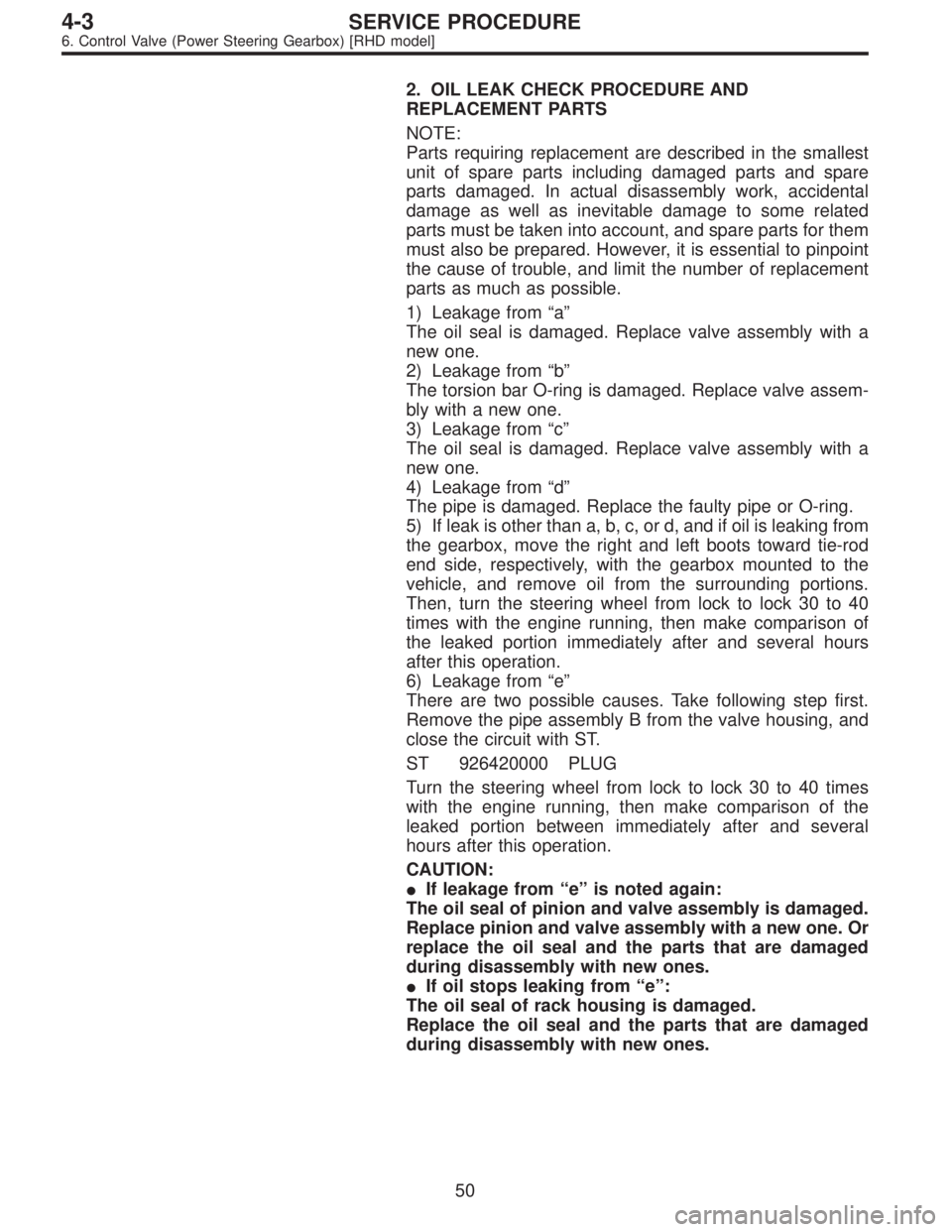
2. OIL LEAK CHECK PROCEDURE AND
REPLACEMENT PARTS
NOTE:
Parts requiring replacement are described in the smallest
unit of spare parts including damaged parts and spare
parts damaged. In actual disassembly work, accidental
damage as well as inevitable damage to some related
parts must be taken into account, and spare parts for them
must also be prepared. However, it is essential to pinpoint
the cause of trouble, and limit the number of replacement
parts as much as possible.
1) Leakage from“a”
The oil seal is damaged. Replace valve assembly with a
new one.
2) Leakage from“b”
The torsion bar O-ring is damaged. Replace valve assem-
bly with a new one.
3) Leakage from“c”
The oil seal is damaged. Replace valve assembly with a
new one.
4) Leakage from“d”
The pipe is damaged. Replace the faulty pipe or O-ring.
5) If leak is other than a, b, c, or d, and if oil is leaking from
the gearbox, move the right and left boots toward tie-rod
end side, respectively, with the gearbox mounted to the
vehicle, and remove oil from the surrounding portions.
Then, turn the steering wheel from lock to lock 30 to 40
times with the engine running, then make comparison of
the leaked portion immediately after and several hours
after this operation.
6) Leakage from“e”
There are two possible causes. Take following step first.
Remove the pipe assembly B from the valve housing, and
close the circuit with ST.
ST 926420000 PLUG
Turn the steering wheel from lock to lock 30 to 40 times
with the engine running, then make comparison of the
leaked portion between immediately after and several
hours after this operation.
CAUTION:
�If leakage from“e”is noted again:
The oil seal of pinion and valve assembly is damaged.
Replace pinion and valve assembly with a new one. Or
replace the oil seal and the parts that are damaged
during disassembly with new ones.
�If oil stops leaking from“e”:
The oil seal of rack housing is damaged.
Replace the oil seal and the parts that are damaged
during disassembly with new ones.
50
4-3SERVICE PROCEDURE
6. Control Valve (Power Steering Gearbox) [RHD model]
Page 1163 of 2890
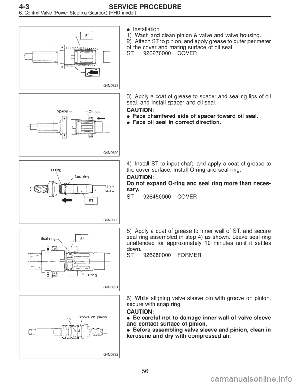
G4M0828
�Installation
1) Wash and clean pinion & valve and valve housing.
2) Attach ST to pinion, and apply grease to outer perimeter
of the cover and mating surface of oil seal.
ST 926270000 COVER
G4M0829
3) Apply a coat of grease to spacer and sealing lips of oil
seal, and install spacer and oil seal.
CAUTION:
�Face chamfered side of spacer toward oil seal.
�Face oil seal in correct direction.
G4M0830
4) Install ST to input shaft, and apply a coat of grease to
the cover surface. Install O-ring and seal ring.
CAUTION:
Do not expand O-ring and seal ring more than neces-
sary.
ST 926450000 COVER
G4M0831
5) Apply a coat of grease to inner wall of ST, and secure
seal ring assembled in step 4) as shown. Leave seal ring
unattended for approximately 10 minutes until it settles
down.
ST 926280000 FORMER
G4M0832
6) While aligning valve sleeve pin with groove on pinion,
secure with snap ring.
CAUTION:
�Be careful not to damage inner wall of valve sleeve
and contact surface of pinion.
�Before assembling valve sleeve and pinion, clean in
kerosene and dry with compressed air.
56
4-3SERVICE PROCEDURE
6. Control Valve (Power Steering Gearbox) [RHD model]
Page 1184 of 2890
E: ASSEMBLY
1) Reassembly precautions
(1) Whenever O-rings, oil seals, and snap rings are
removed, they must be replaced with new ones.
(2) Thoroughly wash parts and allow to dry. They must
be kept free from cleaning oil and dust.
(3) Reassembly procedure must be performed in clean
place. Ensure that parts are kept away from waste
threads or other dust particles.
(4) Cleaning oil tends to stay inside the front casing.
Remove it completely by blowing compressed air.
(5) Ensure that parts are free from rust. (Use specified
hydraulic oil for rust prevention after cleaning and dry-
ing.)
(6) Reverse the sequence of disassembly procedures.
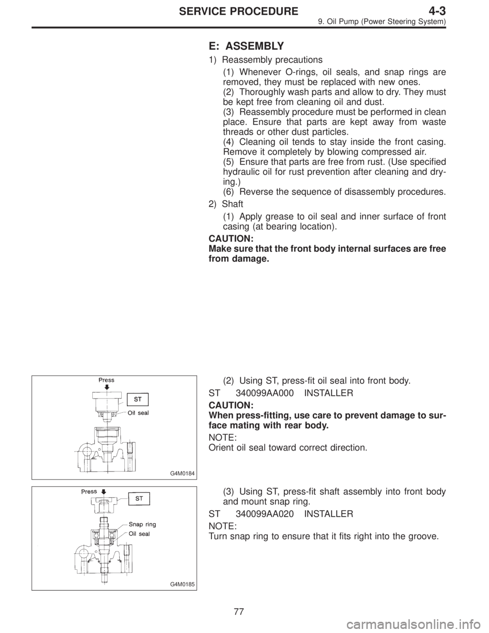
2) Shaft
(1) Apply grease to oil seal and inner surface of front
casing (at bearing location).
CAUTION:
Make sure that the front body internal surfaces are free
from damage.
G4M0184
(2) Using ST, press-fit oil seal into front body.
ST 340099AA000 INSTALLER
CAUTION:
When press-fitting, use care to prevent damage to sur-
face mating with rear body.
NOTE:
Orient oil seal toward correct direction.
G4M0185
(3) Using ST, press-fit shaft assembly into front body
and mount snap ring.
ST 340099AA020 INSTALLER
NOTE:
Turn snap ring to ensure that it fits right into the groove.
77
4-3SERVICE PROCEDURE
9. Oil Pump (Power Steering System)
Page 1185 of 2890
G4M0186
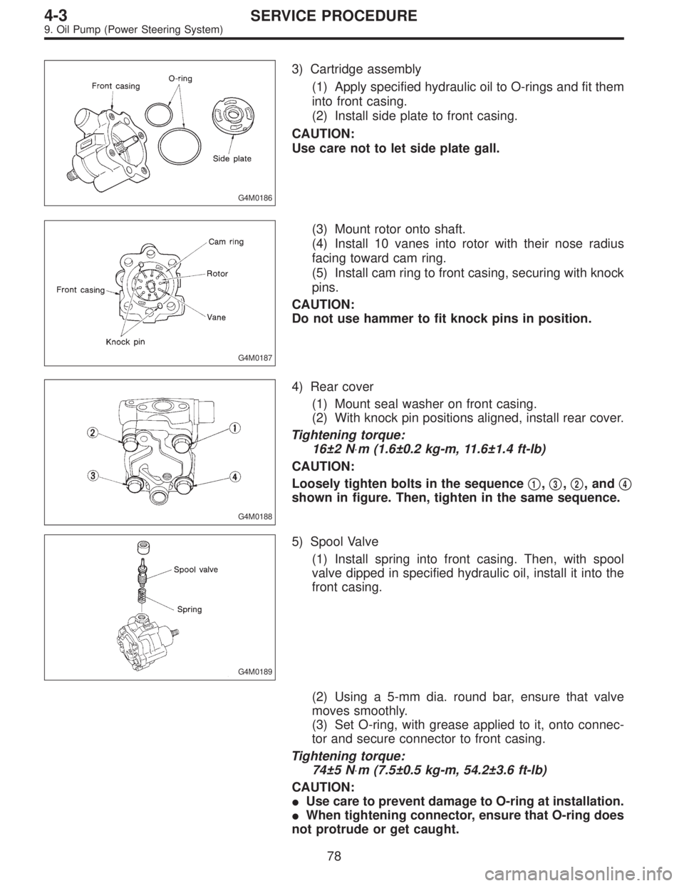
3) Cartridge assembly
(1) Apply specified hydraulic oil to O-rings and fit them
into front casing.
(2) Install side plate to front casing.
CAUTION:
Use care not to let side plate gall.
G4M0187
(3) Mount rotor onto shaft.
(4) Install 10 vanes into rotor with their nose radius
facing toward cam ring.
(5) Install cam ring to front casing, securing with knock
pins.
CAUTION:
Do not use hammer to fit knock pins in position.
G4M0188
4) Rear cover
(1) Mount seal washer on front casing.
(2) With knock pin positions aligned, install rear cover.
Tightening torque:
16±2 N⋅m (1.6±0.2 kg-m, 11.6±1.4 ft-lb)
CAUTION:
Loosely tighten bolts in the sequence�
1,�3,�2, and�4
shown in figure. Then, tighten in the same sequence.
G4M0189
5) Spool Valve
(1) Install spring into front casing. Then, with spool
valve dipped in specified hydraulic oil, install it into the
front casing.
(2) Using a 5-mm dia. round bar, ensure that valve
moves smoothly.
(3) Set O-ring, with grease applied to it, onto connec-
tor and secure connector to front casing.
Tightening torque:
74±5 N⋅m (7.5±0.5 kg-m, 54.2±3.6 ft-lb)
CAUTION:
�Use care to prevent damage to O-ring at installation.
�When tightening connector, ensure that O-ring does
not protrude or get caught.
78
4-3SERVICE PROCEDURE
9. Oil Pump (Power Steering System)
Page 1231 of 2890
G4M0365
3) Measure disc rotor thickness.
NOTE:
Make sure that micrometer is set 5 mm (0.20 in) inward of
rotor outer perimeter.
Disc rotor thickness A
mm (in)Standard
valueService
limitDisc outer dia.
24.0
(0.945)22.0
(0.866)260
(10.24)
G4M0503
B: REMOVAL
1) Remove union bolt and disconnect brake hose from
caliper body assembly.
G4M0366
2) Loosen lock pin.
G4M0367
3) Raise caliper body and move it toward vehicle center to
separate it from support.
G4M0368
4) Remove support from housing.
NOTE:
Remove support only when replacing it or the rotor. It need
not be removed when servicing caliper body assembly.
26
4-4SERVICE PROCEDURE
1. Front Disc Brake
Page 1239 of 2890
G4M0382
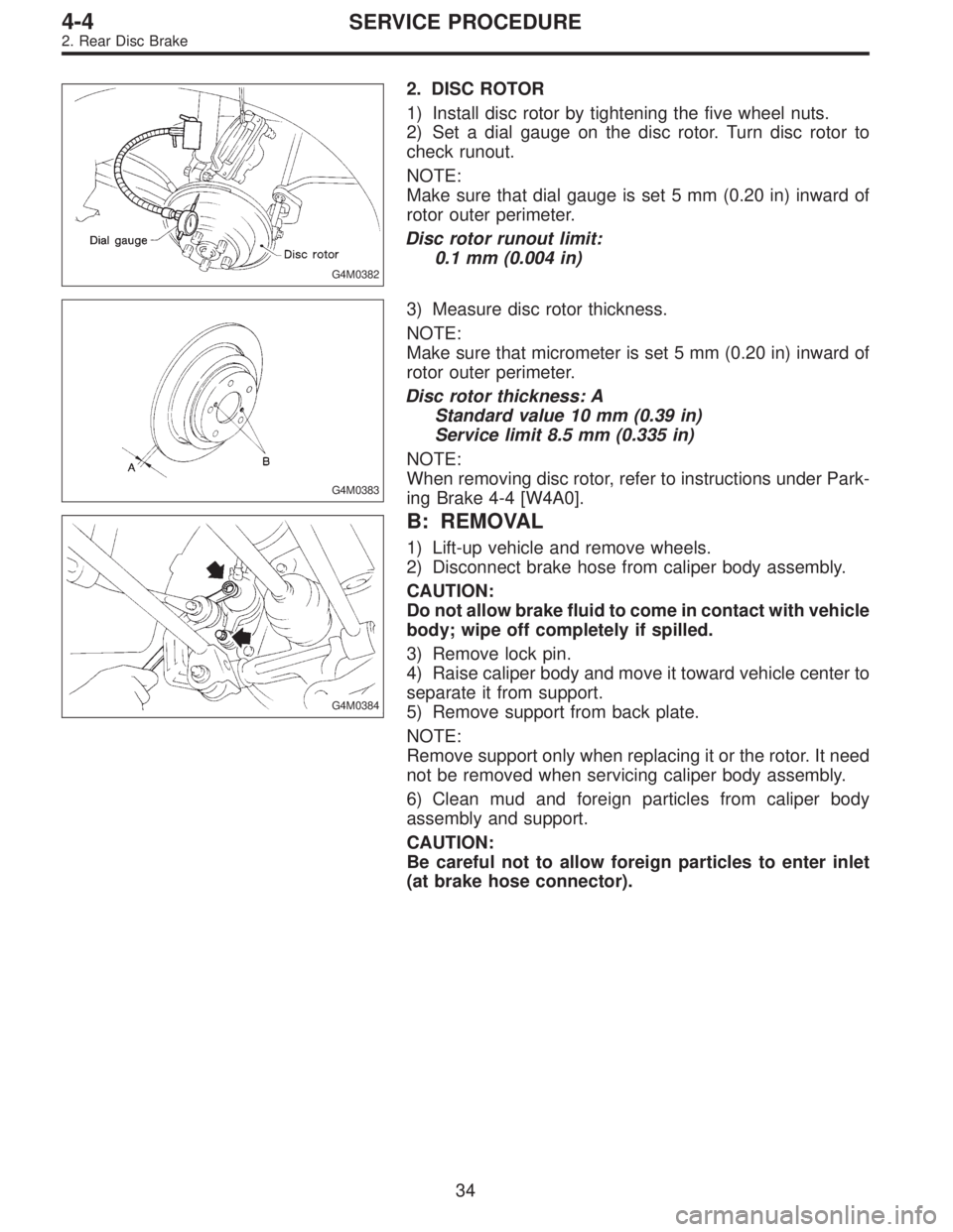
2. DISC ROTOR
1) Install disc rotor by tightening the five wheel nuts.
2) Set a dial gauge on the disc rotor. Turn disc rotor to
check runout.
NOTE:
Make sure that dial gauge is set 5 mm (0.20 in) inward of
rotor outer perimeter.
Disc rotor runout limit:
0.1 mm (0.004 in)
G4M0383
3) Measure disc rotor thickness.
NOTE:
Make sure that micrometer is set 5 mm (0.20 in) inward of
rotor outer perimeter.
Disc rotor thickness: A
Standard value 10 mm (0.39 in)
Service limit 8.5 mm (0.335 in)
NOTE:
When removing disc rotor, refer to instructions under Park-
ing Brake 4-4 [W4A0].
G4M0384
B: REMOVAL
1) Lift-up vehicle and remove wheels.
2) Disconnect brake hose from caliper body assembly.
CAUTION:
Do not allow brake fluid to come in contact with vehicle
body; wipe off completely if spilled.
3) Remove lock pin.
4) Raise caliper body and move it toward vehicle center to
separate it from support.
5) Remove support from back plate.
NOTE:
Remove support only when replacing it or the rotor. It need
not be removed when servicing caliper body assembly.
6) Clean mud and foreign particles from caliper body
assembly and support.
CAUTION:
Be careful not to allow foreign particles to enter inlet
(at brake hose connector).
34
4-4SERVICE PROCEDURE
2. Rear Disc Brake