Page 792 of 2890
 Drive out spring pin�6, and pull out 3-4 fork rod�7and
shifter fork�
8.
NOTE:
When removing rod, keep other rods in neutral. Also, when
pulling out straight pin, remove it toward inside of")
B3M0333B
3) Drive out spring pin�6, and pull out 3-4 fork rod�7and
shifter fork�
8.
NOTE:
When removing rod, keep other rods in neutral. Also, when
pulling out straight pin, remove it toward inside of case so
that it may not hit against case.
4) Drive out straight pin�
9, and pull out 1-2 fork rod�10and
shifter fork�
11.
G3M0602
5) Pull out straight pin�12, and remove idler gear shaft�13,
reverse idler gear�
14and washer�15.
6) Remove outer snap ring�
16, and pull out reverse shifter
rod arm�
17from reverse fork rod�18. Then take out ball,
spring and interlock plunger from rod.
And then remove rod.
NOTE:
When pulling out reverse shifter rod arm, be careful not to
let ball pop out of arm.
7) Remove reverse shifter lever�
19.
G3M0546
8) Remove differential side retainers using ST.
ST 499787000 WRENCH ASSY
G3M0547
9) Remove outer snap ring�20and pull out speedometer
driven gear�
21. Next, remove vehicle speed sensor 2, oil
seal, speedometer shaft�
22and washer.
36
3-1SERVICE PROCEDURE
4. Transmission Case
Page 794 of 2890
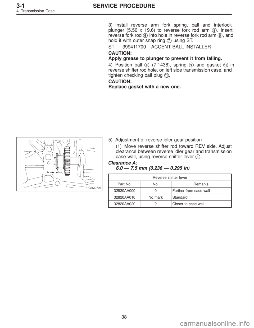
3) Install reverse arm fork spring, ball and interlock
plunger (5.56 x 19.6) to reverse fork rod arm�
5. Insert
reverse fork rod�
6into hole in reverse fork rod arm�5, and
hold it with outer snap ring�
7using ST.
ST 399411700 ACCENT BALL INSTALLER
CAUTION:
Apply grease to plunger to prevent it from falling.
4) Position ball�
8(7.1438), spring�9and gasket�10in
reverse shifter rod hole, on left side transmission case, and
tighten checking ball plug�
11.
CAUTION:
Replace gasket with a new one.
G3M0796
5) Adjustment of reverse idler gear position
(1) Move reverse shifter rod toward REV side. Adjust
clearance between reverse idler gear and transmission
case wall, using reverse shifter lever�
1.
Clearance A:
6.0—7.5 mm (0.236—0.295 in)
Reverse shifter lever
Part No. No. Remarks
32820AA000 0 Further from case wall
32820AA010 No mark Standard
32820AA020 2 Closer to case wall
38
3-1SERVICE PROCEDURE
4. Transmission Case
Page 821 of 2890
G3M0666
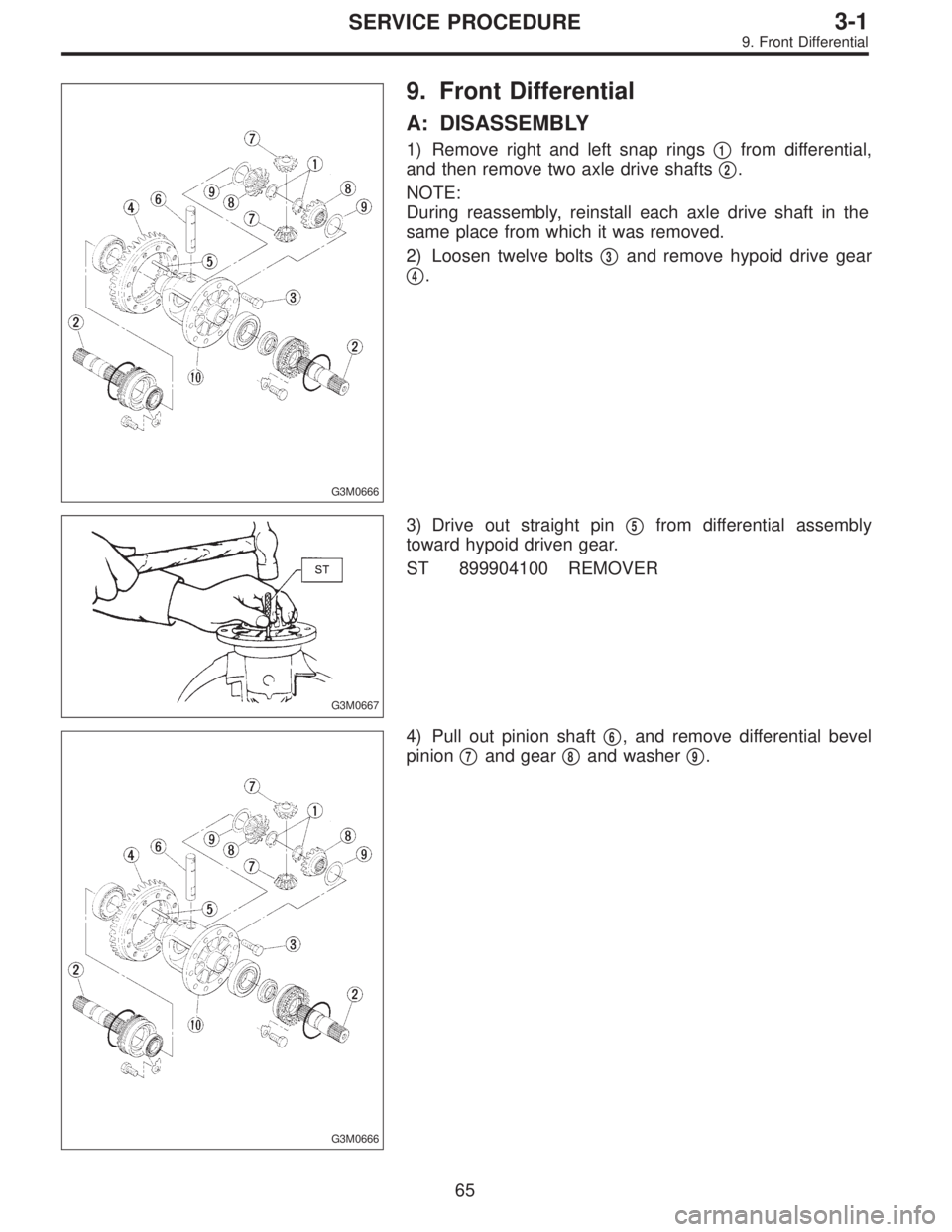
9. Front Differential
A: DISASSEMBLY
1) Remove right and left snap rings�1from differential,
and then remove two axle drive shafts�
2.
NOTE:
During reassembly, reinstall each axle drive shaft in the
same place from which it was removed.
2) Loosen twelve bolts�
3and remove hypoid drive gear
�
4.
G3M0667
3) Drive out straight pin�5from differential assembly
toward hypoid driven gear.
ST 899904100 REMOVER
G3M0666
4) Pull out pinion shaft�6, and remove differential bevel
pinion�
7and gear�8and washer�9.
65
3-1SERVICE PROCEDURE
9. Front Differential
Page 822 of 2890
G3M0668
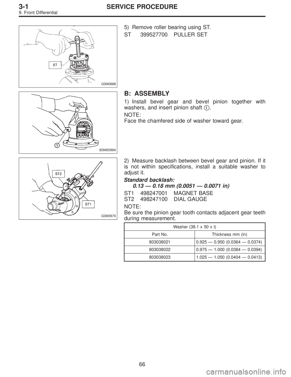
5) Remove roller bearing using ST.
ST 399527700 PULLER SET
B3M0099A
B: ASSEMBLY
1) Install bevel gear and bevel pinion together with
washers, and insert pinion shaft�
1.
NOTE:
Face the chamfered side of washer toward gear.
G3M0670
2) Measure backlash between bevel gear and pinion. If it
is not within specifications, install a suitable washer to
adjust it.
Standard backlash:
0.13—0.18 mm (0.0051—0.0071 in)
ST1 498247001 MAGNET BASE
ST2 498247100 DIAL GAUGE
NOTE:
Be sure the pinion gear tooth contacts adjacent gear teeth
during measurement.
Washer (38.1 x 50 x t)
Part No. Thickness mm (in)
803038021 0.925—0.950 (0.0364—0.0374)
803038022 0.975—1.000 (0.0384—0.0394)
803038023 1.025—1.050 (0.0404—0.0413)
66
3-1SERVICE PROCEDURE
9. Front Differential
Page 889 of 2890
 Apply red lead evenly to the surfaces of three or
four teeth of the crown gear. Rotate the drive pinion in
the forward and reverse directions several times. Then
remove the oil pump housing, and c")
(8) Apply red lead evenly to the surfaces of three or
four teeth of the crown gear. Rotate the drive pinion in
the forward and reverse directions several times. Then
remove the oil pump housing, and check the tooth con-
tact pattern.
If tooth contact is improper, readjust the backlash or
shim thickness.
Checking item Contact pattern Corrective action
Tooth contact
Tooth contact pattern is slightly shifted
toward to under no-load rotation.
[When loaded, contact pattern moves
toward heel.]
B3M0317A
Face contact
Backlash is too large.This may cause noise and chipping at
tooth ends.
B3M0319
Increase thickness of drive pinion height
adjusting shim in order to bring drive pinion
close to crown gear.
B3M0323
Flank contact
Backlash is too small.This may cause noise and stepped wear
on surfaces.
B3M0320
Reduce thickness of drive pinion height
adjusting shim in order to move drive pin-
ion away from crown gear.
B3M0324
Toe contact
(Inside end contact)
Contact areas is small.This may cause chipping at toe ends.
B3M0321
Adjust as for flank contact.
B3M0324
Heel contact
(Outside end contact)
Contact area is small.This may cause chipping at heel ends.
B3M0322
Adjust as for face contact.
B3M0323
: Adjusting direction of drive pinion
: Adjusting direction of crown gear
63
3-2SERVICE PROCEDURE
4. Overall Transmission
Page 995 of 2890

TOOTH CONTACT PATTERN
Condition Contact pattern Adjustment
Correct tooth contact
Tooth contact pattern slightly shifted
towards toe under no load rotation.
(When loaded, contact pattern moves
toward heel.)
B3M0317A
Face contact
Backlash is too large.This may cause noise and chipping at
tooth ends.
B3M0319
Increase thickness of drive pinion height
adjusting shim in order to bring drive
pinion closer to crown gear center.
B3M0323
Flank contact
Backlash is too small.This may cause noise and stepped wear
on surfaces.
B3M0320
Reduce thickness of drive pinion height
adjusting shim in order to move drive
pinion away from crown gear.
B3M0324
Toe contact
Contact area is small.This may cause chipping at toe ends.
B3M0321
Adjust as for flank contact.
B3M0324
Heel contact
Contact area is small.This may cause chipping at heel ends.
B3M0322
Adjust as for face contact.
B3M0323
: Adjusting direction of drive pinion
: Adjusting direction of crown gear
36
3-4SERVICE PROCEDURE
2. Rear Differential
Page 1049 of 2890
G4M0208
1. Wheels and Axles
A: SPECIFICATIONS
1. TIRE AND WHEEL SIZE
Tire size Rim sizeRim offset
mm (in)P.C.D.
mm (in)
Except OUTBACK modelFront and RearP185/70R14
87S14×5 1/2JJ 55 (2.17)
100 (3.94)
dia. P195/60R15
87H15 x 6JJ 55 (2.17)
T-type tireT125/70D15 15 x 4T 53 (2.09)
T135/70D16 16 x 4T 50 (1.97)
OUTBACK modelFront and RearP205/70R15
95S15 x 6JJ 55 (2.17)
T-type tire T135/80D16 16 x 4T 50 (1.97)
NOTE:“T-type”tire for temporary use is supplied as a spare tire.
2. TIRE INFLATION PRESSURE
Tire sizeTire inflation pressure kPa (kg/cm
2, psi)
Light load Full load Trailler towing
Except OUTBACK
modelFront and RearP185/70R14 87S
P195/60R15 87HFt: 220 (2.2, 32)
Rr: 210 (2.1, 30)—
T-type tireT125/70D15
T135/70D16420 (4.2, 60)
OUTBACK modelFront and Rear P205/70R15 95SFt: 200 (2.0, 29)
Rr: 190 (1.9, 28)Ft: 200 (2.0, 2.9)
Rr: 220 (2.2, 32)
T-type tire T135/80D16 420 (4.2, 60)
2
4-2SPECIFICATIONS AND SERVICE DATA
1. Wheels and Axles
Page 1138 of 2890
 Remove flare nuts from control valve of gearbox
assembly, and disconnect upper and lower hoses B and A.
CAUTION:
�Always disconnect hoses B and A in that order.
�Be careful not to damage the hoses")
9) Remove flare nuts from control valve of gearbox
assembly, and disconnect upper and lower hoses B and A.
CAUTION:
�Always disconnect hoses B and A in that order.
�Be careful not to damage the hoses during removal.
10) Remove bolts securing gearbox to crossmember, and
detach gearbox.
G4M0788
B: DISASSEMBLY
1) Disconnect four pipes from gearbox.
2) Secure gearbox removed from vehicle in vice using ST.
ST 926200000 STAND
CAUTION:
Secure the gearbox assembly in a vice using the ST as
shown. Do not attempt to secure it without this ST.
G4M0789
3) Pry off clip from outer end of boot, and slide boot toward
tie-rod end.
G4M0790
4) Using ST, remove lock wire from inner end of boot, and
remove boot.
ST 927590000 WRENCH
G4M0791
5) Extend rack approximately 40 mm (1.57 in) out. Unlock
lock wire at lock washer on each side of tie-rod end using
a standard screwdriver.
CAUTION:
Be careful not to scratch rack surface as oil leaks may
result.
31
4-3SERVICE PROCEDURE
4. Steering Gearbox (Power Steering System) [RHD model]
P.C.D.
mm (in)
Except OUTBACK modelFront and RearP185/70R14
87S14×5 1/2JJ 55 (2.17)
100 (3.94)")