Page 1655 of 2890

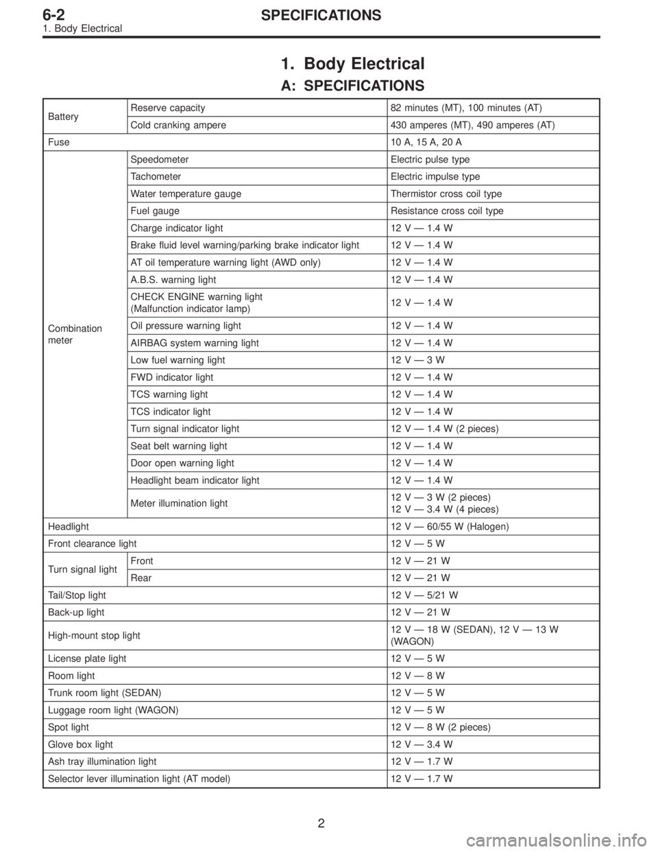
1. Body Electrical
A: SPECIFICATIONS
BatteryReserve capacity 82 minutes (MT), 100 minutes (AT)
Cold cranking ampere 430 amperes (MT), 490 amperes (AT)
Fuse10 A, 15 A, 20 A
Combination
meterSpeedometer Electric pulse type
Tachometer Electric impulse type
Water temperature gauge Thermistor cross coil type
Fuel gauge Resistance cross coil type
Charge indicator light 12 V—1.4 W
Brake fluid level warning/parking brake indicator light 12 V—1.4 W
AT oil temperature warning light (AWD only) 12 V—1.4 W
A.B.S. warning light 12 V—1.4 W
CHECK ENGINE warning light
(Malfunction indicator lamp)12 V—1.4 W
Oil pressure warning light 12 V—1.4 W
AIRBAG system warning light 12 V—1.4 W
Low fuel warning light 12 V—3W
FWD indicator light 12 V—1.4 W
TCS warning light 12 V—1.4 W
TCS indicator light 12 V—1.4 W
Turn signal indicator light 12 V—1.4 W (2 pieces)
Seat belt warning light 12 V—1.4 W
Door open warning light 12 V—1.4 W
Headlight beam indicator light 12 V—1.4 W
Meter illumination light12 V—3 W (2 pieces)
12 V—3.4 W (4 pieces)
Headlight 12 V—60/55 W (Halogen)
Front clearance light 12 V—5W
Turn signal lightFront 12 V—21 W
Rear 12 V—21 W
Tail/Stop light 12 V—5/21 W
Back-up light 12 V—21 W
High-mount stop light12 V—18 W (SEDAN), 12 V—13 W
(WAGON)
License plate light 12 V—5W
Room light 12 V—8W
Trunk room light (SEDAN) 12 V—5W
Luggage room light (WAGON) 12 V—5W
Spot light 12 V—8 W (2 pieces)
Glove box light 12 V—3.4 W
Ash tray illumination light 12 V—1.7 W
Selector lever illumination light (AT model) 12 V—1.7 W
2
6-2SPECIFICATIONS
1. Body Electrical
Page 1668 of 2890
B6M0238
3) Unfasten holddown clip which secures harness, and
disconnect connectors from body harness.
4) Move combination switch to respective positions and
check continuity between terminals as indicated in the fol-
lowing tables:
Lighting switch
Terminal
Switch positionc-1 c-2 c-3
OFF
Tail��
*��
Head���
Parking switch
Terminal
Switch positionc-10 c-11 c-9
OFF��
*XX
ON��
Dimmer and passing switch
Terminal
Switch positiona-3 a-2 a-1 a-4
Flash��
�
*���
Low beam��
*���
HI-beam��
G6M0111
2. HEADLIGHT RELAY
Check continuity between terminals as indicated in table
below, when connecting the battery to terminal No. 1 and
No. 3.
When current flows.Between terminals
No. 2 and No. 4Continuity exists.
When current does not flow.Between terminals
No. 2 and No. 4Continuity does not
exist.
Between terminals
No. 1 and No. 3Continuity exists.
12
6-2SERVICE PROCEDURE
4. Headlight
Page 1670 of 2890

B6M0055A
B6M0056A
5. Stop and Tail Light
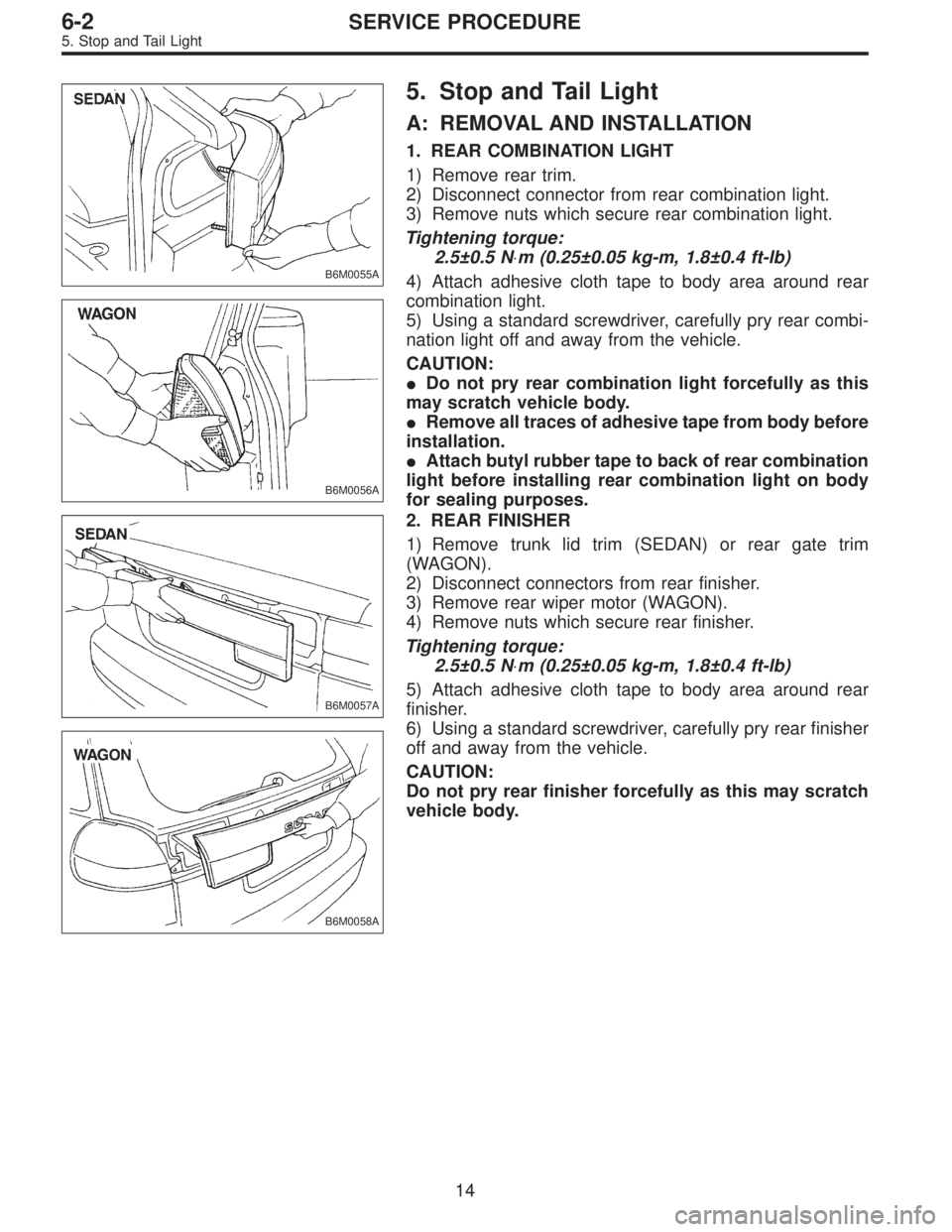
A: REMOVAL AND INSTALLATION
1. REAR COMBINATION LIGHT
1) Remove rear trim.
2) Disconnect connector from rear combination light.
3) Remove nuts which secure rear combination light.
Tightening torque:
2.5±0.5 N⋅m (0.25±0.05 kg-m, 1.8±0.4 ft-lb)
4) Attach adhesive cloth tape to body area around rear
combination light.
5) Using a standard screwdriver, carefully pry rear combi-
nation light off and away from the vehicle.
CAUTION:
�Do not pry rear combination light forcefully as this
may scratch vehicle body.
�Remove all traces of adhesive tape from body before
installation.
�Attach butyl rubber tape to back of rear combination
light before installing rear combination light on body
for sealing purposes.
B6M0057A
B6M0058A
2. REAR FINISHER
1) Remove trunk lid trim (SEDAN) or rear gate trim
(WAGON).
2) Disconnect connectors from rear finisher.
3) Remove rear wiper motor (WAGON).
4) Remove nuts which secure rear finisher.
Tightening torque:
2.5±0.5 N⋅m (0.25±0.05 kg-m, 1.8±0.4 ft-lb)
5) Attach adhesive cloth tape to body area around rear
finisher.
6) Using a standard screwdriver, carefully pry rear finisher
off and away from the vehicle.
CAUTION:
Do not pry rear finisher forcefully as this may scratch
vehicle body.
14
6-2SERVICE PROCEDURE
5. Stop and Tail Light
Page 1671 of 2890
B6M0340A
3. HIGH-MOUNT STOP LIGHT (SEDAN)
1) Disconnect connector of high-mount stop light from
body harness.
2) Remove screws which secure high-mount stop light to
rear shelf panel.
3) Remove high-mount stop light.
B6M0341A
4. HIGH-MOUNT STOP LIGHT (WAGON)
1) Remove high-mount stop light cover from rear gate trim
panel.
2) Remove screws which secure high-mount stop light.
3) Remove high-mount stop light while disconnecting con-
nector from body harness.
5. STOP LIGHT SWITCH
Refer to 4-5 [C100] (MT) or 4-5 [C200] (AT) as for removal
and installation of stop light switch.
NOTE:
When installing the stop light switch, adjust the pedal
height by adjusting the stop light switch position.
6. COMBINATION SWITCH
Refer to 6-2 [W4B3] as for removal and installation of com-
bination switch.
B: DISASSEMBLY AND ASSEMBLY
1. COMBINATION SWITCH
Refer to 6-2 [W4C1] as for disassembly and assembly of
combination switch.
15
6-2SERVICE PROCEDURE
5. Stop and Tail Light
Page 1672 of 2890
B6M0059A
C: INSPECTION
1. STOP LIGHT SWITCH (ON-CAR)
Without cruise control model
1) Disconnect connector of stop light switch from body
harness.
2) Check continuity between terminals when push rod is
pushed in 4.0 to 4.5 mm (0.157 to 0.177 in) from end of
outer case.
Terminal
Switch position12
When push rod is
pushed in.
When push rod is
released.��
B6M0060A
With cruise control model
1) Disconnect connector of stop light switch from body
harness.
2) Check continuity between terminals when push rod is
pushed in 1.5 to 3.0 mm (0.059 to 0.118 in) from end of
outer case.
Terminal
Switch position1234
When push rod is
pushed in.��
When push rod is
released.��
16
6-2SERVICE PROCEDURE
5. Stop and Tail Light
Page 1673 of 2890
B6M0342
With TCS model
1) Disconnect connector of stop light switch from body
harness.
2) Check continuity between terminals when push rod is
pushed in 1.2 to 3.2 mm (0.047 to 0.126 in) from end of
outer case.
Terminal
Switch position1234
When push rod is
pushed in.��
When push rod is
released.��
2. COMBINATION SWITCH (ON-CAR)
Refer to 6-2 [W4D1] as for inspection of combination
switch.
G6M0112
3. TAIL AND ILLUMINATION RELAY
Check continuity between terminals as indicated in table
below, when connecting battery to terminal No. 1 and No. 3
When current flows.Between terminals
No. 2 and No. 4Continuity exists.
When current does not flow.Between terminals
No. 2 and No. 4Continuity does not
exist.
Between terminals
No. 1 and No. 3Continuity exists.
17
6-2SERVICE PROCEDURE
5. Stop and Tail Light
Page 1830 of 2890

3) Start the engine.
NOTE:
�Ensure the selector lever is placed in the“P”position
before starting. (AT vehicles)
�Depress clutch pedal when starting the engine. (MT
vehicles)
4) Using the selector lever or shift lever, turn the“P”posi-
tion switch and the“N”position switch to ON.
5) Depress the brake pedal to turn the brake switch ON.
(AT vehicles)
6) Keep engine speed in the 2,500—3,000 rpm range for
40 seconds.
NOTE:
On models without tachometer, use the Subaru select
monitor or tachometer (Secondary pickup type).
7) Place the selector lever or shift lever in the“D”position
(AT vehicles) or“1st”gear (MT vehicles) and drive the
vehicle at 5 to 10 km/h (3 to 6 MPH).
NOTE:
�On AWD vehicles, release the parking brake.
�The speed difference between front and rear wheels
may light either the ABS or the ABS/TCS warning light, but
this indicates no malfunctions. When engine control diag-
nosis is finished, perform the ABS or the ABS/TCS memory
clearance procedure of self-diagnosis system.
4-4b [T6D2] or [T9K0], 4-4c [T6D2] or [T9J0].>
8) Using the OBD-II general scan tool, check for diagnos-
tic trouble code(s) and record the result(s).
NOTE:
�For detailed operation procedures, refer to the OBD-II
General Scan Tool Instruction Manual.
�For details concerning diagnostic trouble codes, refer to
the DIAGNOSTIC TROUBLE CODE (DTC) LIST, 2-7
[T10A0].
H2M1149
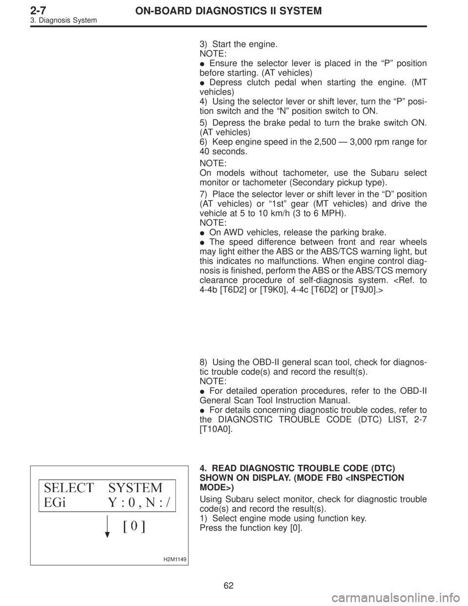
4. READ DIAGNOSTIC TROUBLE CODE (DTC)
SHOWN ON DISPLAY. (MODE FB0
MODE>)
Using Subaru select monitor, check for diagnostic trouble
code(s) and record the result(s).
1) Select engine mode using function key.
Press the function key [0].
62
2-7ON-BOARD DIAGNOSTICS II SYSTEM
3. Diagnosis System
Page 1896 of 2890

OBD0145A
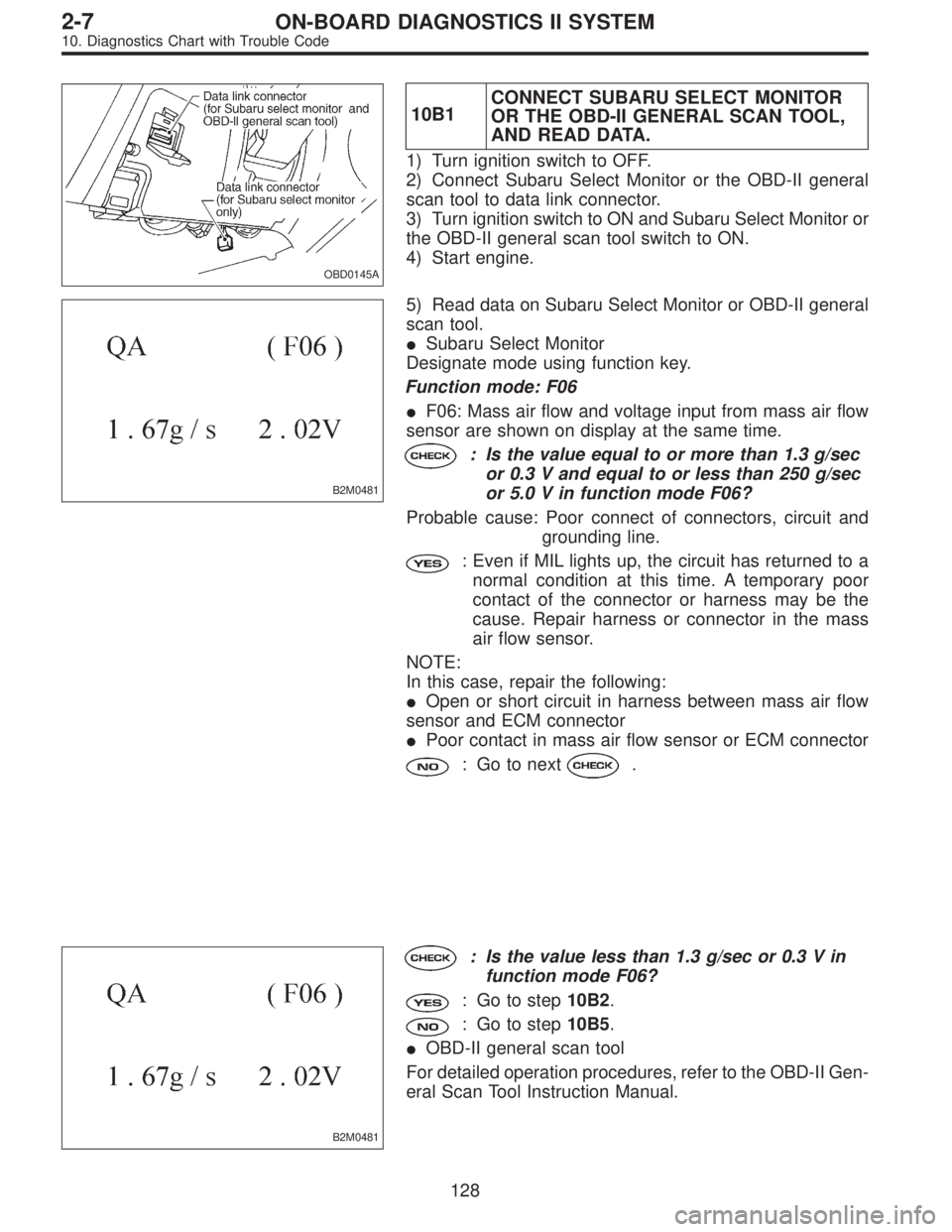
10B1CONNECT SUBARU SELECT MONITOR
OR THE OBD-II GENERAL SCAN TOOL,
AND READ DATA.
1) Turn ignition switch to OFF.
2) Connect Subaru Select Monitor or the OBD-II general
scan tool to data link connector.
3) Turn ignition switch to ON and Subaru Select Monitor or
the OBD-II general scan tool switch to ON.
4) Start engine.
B2M0481
5) Read data on Subaru Select Monitor or OBD-II general
scan tool.
�Subaru Select Monitor
Designate mode using function key.
Function mode: F06
�F06: Mass air flow and voltage input from mass air flow
sensor are shown on display at the same time.
: Is the value equal to or more than 1.3 g/sec
or 0.3 V and equal to or less than 250 g/sec
or 5.0 V in function mode F06?
Probable cause: Poor connect of connectors, circuit and
grounding line.
: Even if MIL lights up, the circuit has returned to a
normal condition at this time. A temporary poor
contact of the connector or harness may be the
cause. Repair harness or connector in the mass
air flow sensor.
NOTE:
In this case, repair the following:
�Open or short circuit in harness between mass air flow
sensor and ECM connector
�Poor contact in mass air flow sensor or ECM connector
: Go to next.
B2M0481
: Is the value less than 1.3 g/sec or 0.3 V in
function mode F06?
: Go to step10B2.
: Go to step10B5.
�OBD-II general scan tool
For detailed operation procedures, refer to the OBD-II Gen-
eral Scan Tool Instruction Manual.
128
2-7ON-BOARD DIAGNOSTICS II SYSTEM
10. Diagnostics Chart with Trouble Code