Page 1921 of 2890

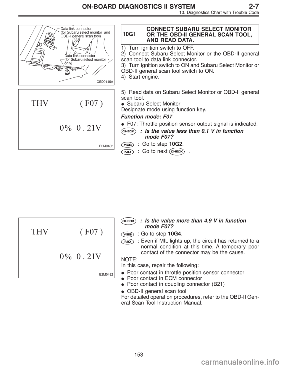
OBD0145A
10G1CONNECT SUBARU SELECT MONITOR
OR THE OBD-II GENERAL SCAN TOOL,
AND READ DATA.
1) Turn ignition switch to OFF.
2) Connect Subaru Select Monitor or the OBD-II general
scan tool to data link connector.
3) Turn ignition switch to ON and Subaru Select Monitor or
OBD-II general scan tool switch to ON.
4) Start engine.
B2M0482
5) Read data on Subaru Select Monitor or OBD-II general
scan tool.
�Subaru Select Monitor
Designate mode using function key.
Function mode: F07
�F07: Throttle position sensor output signal is indicated.
: Is the value less than 0.1 V in function
mode F07?
: Go to step10G2.
: Go to next.
B2M0482
: Is the value more than 4.9 V in function
mode F07?
: Go to step10G4.
: Even if MIL lights up, the circuit has returned to a
normal condition at this time. A temporary poor
contact of the connector may be the cause.
NOTE:
In this case, repair the following:
�Poor contact in throttle position sensor connector
�Poor contact in ECM connector
�Poor contact in coupling connector (B21)
�OBD-II general scan tool
For detailed operation procedures, refer to the OBD-II Gen-
eral Scan Tool Instruction Manual.
153
2-7ON-BOARD DIAGNOSTICS II SYSTEM
10. Diagnostics Chart with Trouble Code
Page 2221 of 2890

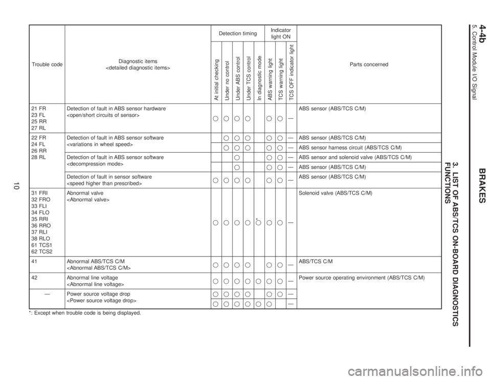
3. LIST OF ABS/TCS ON-BOARD DIAGNOSTICS
FUNCTIONS
Trouble codeDiagnostic items
Detection timingIndicator
light ON
Parts concerned
At initial checking
Under no control
Under ABS control
Under TCS control
In diagnostic mode
ABS warning light
TCS warning light
TCS OFF indicator light
21 FR
23 FL
25 RR
27 RLDetection of fault in ABS sensor hardware
���� ��—ABS sensor (ABS/TCS C/M)
22 FR
24 FL
26 RR
28 RLDetection of fault in ABS sensor software
��� ��—ABS sensor (ABS/TCS C/M)
��� ��—ABS sensor harness circuit (ABS/TCS C/M)
Detection of fault in ABS sensor software
���—ABS sensor and solenoid valve (ABS/TCS C/M)
���—ABS sensor (ABS/TCS C/M)
Detection of fault in sensor software
���� ��—ABS sensor (ABS/TCS C/M)
31 FRI
32 FRO
33 FLI
34 FLO
35 RRI
36 RRO
37 RLI
38 RLO
61 TCS1
62 TCS2Abnormal valve
����*
���—Solenoid valve (ABS/TCS C/M)
41 Abnormal ABS/TCS C/M
���� ��—ABS/TCS C/M
42 Abnormal line voltage
�������—Power source operating environment (ABS/TCS C/M)
—Power source voltage drop
���� ��—
������—
*: Except when trouble code is being displayed.
10
4-4bBRAKES
5. Control Module I/O Signal
Page 2222 of 2890
Trouble codeDiagnostic items
Detection timingIndicator
light ON
Parts concerned
At initial checking
Under no control
Under ABS control
Under TCS control
In diagnostic mode
ABS warning light
TCS warning light
TCS OFF indicator light
43 Abnormal EGI communication line
���—�—AET communication line (ABS/TCS C/M)
���—�—
�—�—
����—�—AEB communication line (ABS/TCS C/M)
����—�—
��—�—
����—�—AEC communication line (ABS/TCS C/M)
����—�—
���—�—
—Abnormal EGI communication line
���——�EAM communication line (ABS/TCS C/M)
51 Abnormal valve relay
���—Valve relay (ABS/TCS C/M)
Abnormal valve relay
���� ��—Valve relay (ABS/TCS C/M)
���� ��—
52 Abnormal motor system
��� ��—Motor (ABS/TCS C/M)
Abnormal motor system
�� ��—Motor (ABS/TCS C/M)
Abnormal motor system
���—
11
4-4bBRAKES
5. Control Module I/O Signal
Page 2223 of 2890

Trouble codeDiagnostic items
Detection timingIndicator
light ON
Parts concerned
At initial checking
Under no control
Under ABS control
Under TCS control
In diagnostic mode
ABS warning light
TCS warning light
TCS OFF indicator light
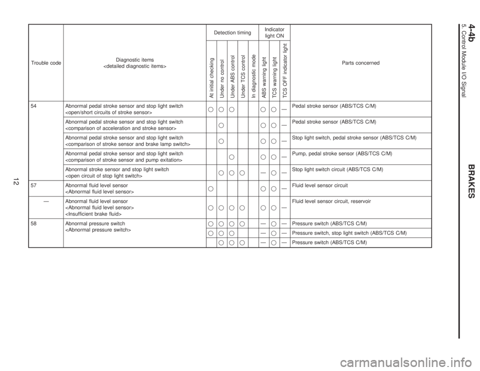
54 Abnormal pedal stroke sensor and stop light switch
��� ��—Pedal stroke sensor (ABS/TCS C/M)
Abnormal pedal stroke sensor and stop light switch
���—Pedal stroke sensor (ABS/TCS C/M)
Abnormal pedal stroke sensor and stop light switch
���—Stop light switch, pedal stroke sensor (ABS/TCS C/M)
Abnormal pedal stroke sensor and stop light switch
���—Pump, pedal stroke sensor (ABS/TCS C/M)
Abnormal stroke sensor and stop light switch
���—�—Stop light switch circuit (ABS/TCS C/M)
57 Abnormal fluid level sensor
���—Fluid level sensor circuit
—Abnormal fluid level sensor
���� ��—Fluid level sensor circuit, reservoir
58 Abnormal pressure switch
����—�—Pressure switch (ABS/TCS C/M)
���—�—Pressure switch, stop light switch (ABS/TCS C/M)
���—�—Pressure switch (ABS/TCS C/M)
12
4-4bBRAKES
5. Control Module I/O Signal
Page 2306 of 2890

Diagnostic items
(select monitor FB0)CodeDisplay screen
(FB0)Diagnostic items (select monitor FB1) Display screen (FB1)Ref. to
4-4b
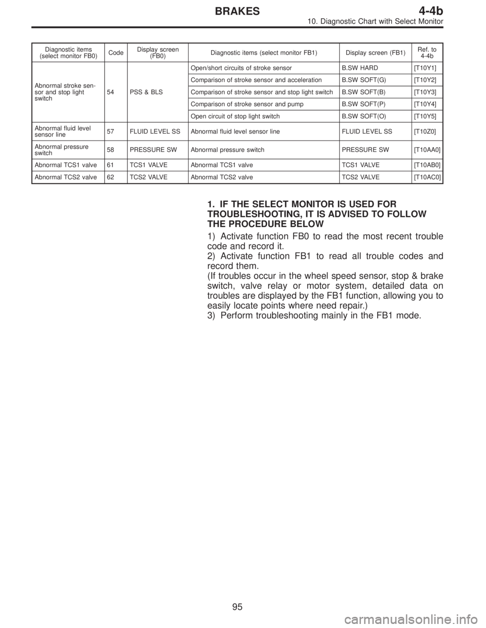
Abnormal stroke sen-
sor and stop light
switch54 PSS & BLSOpen/short circuits of stroke sensor B.SW HARD [T10Y1]
Comparison of stroke sensor and acceleration B.SW SOFT(G) [T10Y2]
Comparison of stroke sensor and stop light switch B.SW SOFT(B) [T10Y3]
Comparison of stroke sensor and pump B.SW SOFT(P) [T10Y4]
Open circuit of stop light switch B.SW SOFT(O) [T10Y5]
Abnormal fluid level
sensor line57 FLUID LEVEL SS Abnormal fluid level sensor line FLUID LEVEL SS [T10Z0]
Abnormal pressure
switch58 PRESSURE SW Abnormal pressure switch PRESSURE SW [T10AA0]
Abnormal TCS1 valve 61 TCS1 VALVE Abnormal TCS1 valve TCS1 VALVE [T10AB0]
Abnormal TCS2 valve 62 TCS2 VALVE Abnormal TCS2 valve TCS2 VALVE [T10AC0]
1. IF THE SELECT MONITOR IS USED FOR
TROUBLESHOOTING, IT IS ADVISED TO FOLLOW
THE PROCEDURE BELOW
1) Activate function FB0 to read the most recent trouble
code and record it.
2) Activate function FB1 to read all trouble codes and
record them.
(If troubles occur in the wheel speed sensor, stop & brake
switch, valve relay or motor system, detailed data on
troubles are displayed by the FB1 function, allowing you to
easily locate points where need repair.)
3) Perform troubleshooting mainly in the FB1 mode.
95
4-4bBRAKES
10. Diagnostic Chart with Select Monitor
Page 2801 of 2890
19. LIGHTING
(TAIL LIGHT⋅ILLUMINATION LIGHT⋅ETC.) SYSTEM
�LHD model
BU21-03A
71
6-3WIRING DIAGRAM
6. Wiring Diagram
Page 2803 of 2890
19. LIGHTING
(TAIL LIGHT⋅ILLUMINATION LIGHT⋅ETC.) SYSTEM
�RHD model
BUR21-01A
73
6-3WIRING DIAGRAM
6. Wiring Diagram
Page 2837 of 2890
![SUBARU LEGACY 1996 Service Repair Manual 7. Electrical Unit Location
Electrical unit Refer to;
A.B.S. control module 4-4a [T300]
A.B.S. G sensor (MT) 4-4a [T300]
A/C compressor relay�
7
A/C fuse�11
A/C main fan relay 1�10
A/C main fan relay SUBARU LEGACY 1996 Service Repair Manual 7. Electrical Unit Location
Electrical unit Refer to;
A.B.S. control module 4-4a [T300]
A.B.S. G sensor (MT) 4-4a [T300]
A/C compressor relay�
7
A/C fuse�11
A/C main fan relay 1�10
A/C main fan relay](/manual-img/17/57433/w960_57433-2836.png)
7. Electrical Unit Location
Electrical unit Refer to;
A.B.S. control module 4-4a [T300]
A.B.S. G sensor (MT) 4-4a [T300]
A/C compressor relay�
7
A/C fuse�11
A/C main fan relay 1�10
A/C main fan relay 2�8
A/C pressure switch�2
A/C sub fan relay 2�9
ATF temperature sensor 2-7 [T2B1]
Blower motor resistor�
26
Blower relay�13
Camshaft position sensor 2-7 [T2A2]
Check connector�
25
Clutch switch (MT) 6-2 [T300]
Crankshaft position sensor 2-7 [T2A2]
Cruise control module 6-2 [T300]
Cruise control pump 6-2 [T300]
Data link connector (for OBD-II G.S.T.) 2-7 [T2A1]
Data link connector (for S.S.M.) 2-7 [T2A1]
Diagnosis connector 4-4a [T300]
Diagnosis terminal (Ground) 4-4a [T300]
Door lock timer�
27
Engine control module 2-7 [T2A1]
Engine coolant temperature sensor 2-7 [T2A2]
Engine hood switch (Security) 6-2 [K6A0]
Evaporator thermoswitch�
29
F/B�15
FRESH/RECIRC actuator�28
Fuel pump relay 2-7 [T2A3]
Fuel gauge module�
31
Fuel gauge sub module (AWD)�32
FWD switch (AT)�1
Headlight alarm relay (Security) 6-2 [K6A0]
Headlight relay LH�
5
Headlight relay RH�6
Horn relay�14
Electrical unit Refer to;
Hydraulic unit (A.B.S.) 4-4a [T300]
Ignition coil 2-7 [T2A3]
Ignitor 2-7 [T2A3]
Idle air control solenoid valve 2-7 [T2A3]
Illumination control module�
21
Inhibitor switch 6-2 [T300]
Knock sensor 2-7 [T2A2]
Main fan relay�
19
Main relay 2-7 [T2A3]
Mass air flow sensor 2-7 [T2A2]
Mode actuator�
12
M/B�4
Oil pressure switch�3
Oxygen sensor 2-7 [T2A2]
Pedal stroke sensor (T.C.S.) 4-4b [T300]
Power window and sunroof relay�
24
Power window circuit breaker�23
Purge control solenoid valve 2-7 [T2A3]
Rear defogger relay�
17
Seat belt timer�20
Security control module 6-2 [K6A0]
Shift lock control module�
22
Starter interrupt relay (Security) 6-2 [K6A0]
Stop & brake switch (With cruise con-
trol)6-2 [T300]
Sunroof control module�
30
Tail and illumination relay�18
T.C.S. control module 4-4b [T300]
T.C.S. motor relay 4-4b [T300]
T.C.S. valve relay 4-4b [T300]
Throttle position sensor 2-7 [T2A2]
Test mode connector 2-7 [T2A1]
Transmission control module 2-7 [T2B1]
Turn & hazard module�
16
Vehicle speed sensor 1 2-7 [T2B1]
Vehicle speed sensor 2 2-7 [T2B1]
107
6-3WIRING DIAGRAM
7. Electrical Unit Location