1996 SUBARU LEGACY airbag off
[x] Cancel search: airbag offPage 13 of 2890

SERVICE
PROCEDURE
[w3A11
5-5b
3
.
Airbag
Module
3
.
Airbag
Module
A
:
REMOVAL
1
.
DRIVER
SIDE
1)
Set
front
wheels
in
straight
ahead
position
.
2)
Turn
ignition
switch
off
.
3)
Disconnect
ground
cable
from
battery
and
wait
forat
least
20
seconds
before
starting
work
.
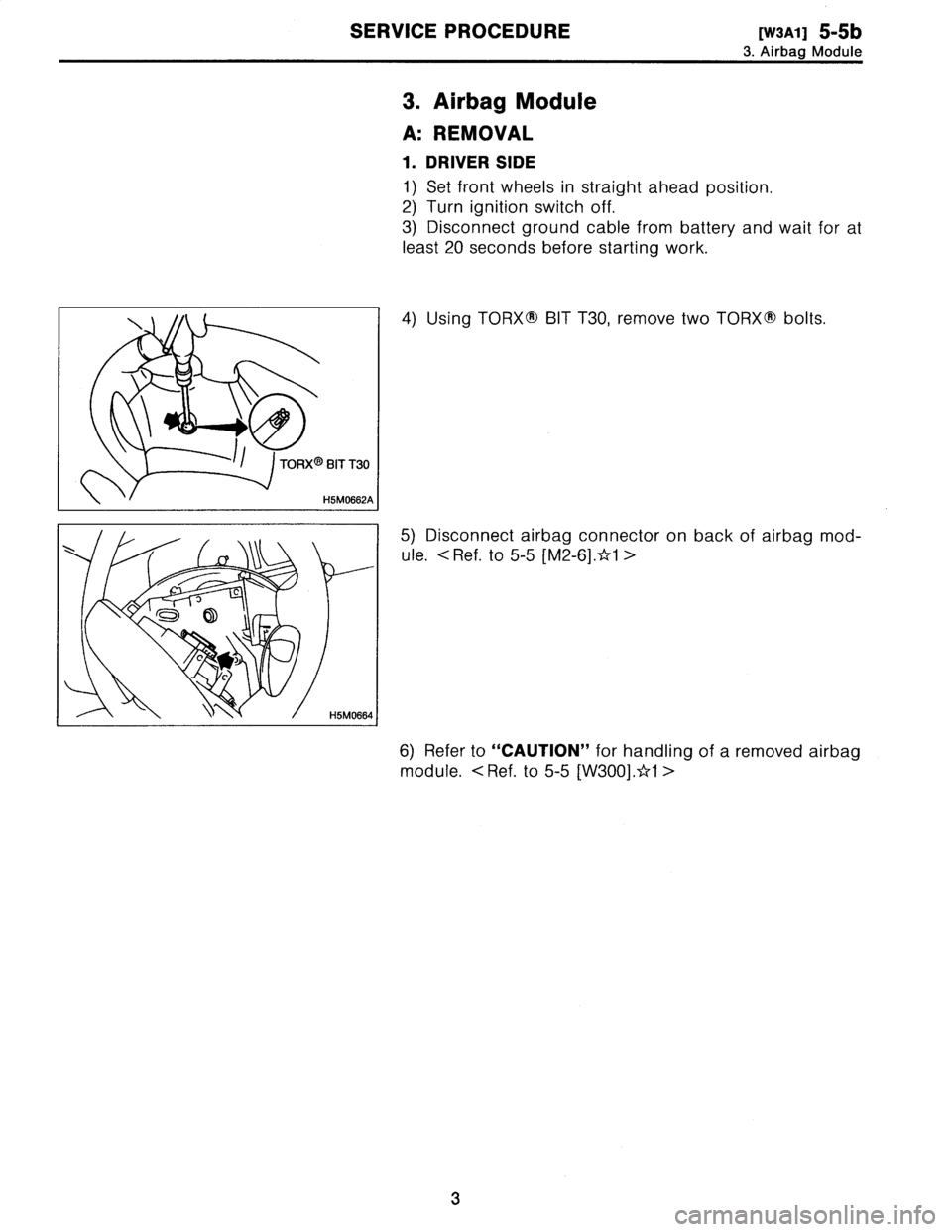
4)
Using
TORX9
BIT
T30,
remove
two
TORXO
bolts
.
5)
Disconnect
airbag
connector
on
back
of
airbag
mod-
ule
.
<
Ref
.
to
5-5[M2-6].*1
>
6)
Refer
to
"CAUTION"
for
handling
of
a
removed
airbag
module
.
<
Ref
.
to
5-5
[W300]
.*1
>
3
Page 14 of 2890
![SUBARU LEGACY 1996 Service Repair Manual
5-5b
[W6A0]
SERVICE
PROCEDURE
6
.
Airbag
Control
Module
AB6
9~v~
BSM0400A
e
B5M0105
I
6
.
Airbag
Control
Module
A
:
REMOVAL
1)
Turn
ignition
switch
off
.
2)
Disconnect
ground
cablefrom
battery SUBARU LEGACY 1996 Service Repair Manual
5-5b
[W6A0]
SERVICE
PROCEDURE
6
.
Airbag
Control
Module
AB6
9~v~
BSM0400A
e
B5M0105
I
6
.
Airbag
Control
Module
A
:
REMOVAL
1)
Turn
ignition
switch
off
.
2)
Disconnect
ground
cablefrom
battery](/manual-img/17/57433/w960_57433-13.png)
5-5b
[W6A0]
SERVICE
PROCEDURE
6
.
Airbag
Control
Module
AB6
9~v~
BSM0400A
e
B5M0105
I
6
.
Airbag
Control
Module
A
:
REMOVAL
1)
Turn
ignition
switch
off
.
2)
Disconnect
ground
cablefrom
battery
and
wait
forat
least
20
seconds
before
starting
work
.
3)
Remove
lower
cover
.
<
Ref
.
to
5-4
[W1A0]
.*1
>
Disconnect
airbag
connector
(AB3)
and
(AB8)below
steering
column
.
CAUTION
:
Do
notreconnect
airbag
connector
at
steering
column
until
airbag
control
module
is
securely
re-installed
.
4)
Remove
console
box
.
<
Ref
.
to
5-4
[W1A0]
.*1
>
5)
Disconnect
12-pinyellow
connector
fromairbagcon-
trol
module
.
<
Ref
.
to
5-5[M2-6].*1
>
6)
Using
TORXS
BIT
T40
(Tamper
resistant
type),
remove
two
TORXS
bolts
.
Discard
theold
TORXM
bolts
.
CAUTION
:
Use
new
TORXS
bolts
during
re-assembly
.
4
Page 15 of 2890
![SUBARU LEGACY 1996 Service Repair Manual
SERVICE
PROCEDURE
[W7AO]
5-5b
7
.
Combination
Switch
7
.
Combination
Switch
)
0)0
C
J
~
AB
,
.,
.
-^o/
G5M0312
A
:
REMOVAL
1)
Turn
ignition
switch
off
.
2)
Disconnect
ground
cable
from
batt SUBARU LEGACY 1996 Service Repair Manual
SERVICE
PROCEDURE
[W7AO]
5-5b
7
.
Combination
Switch
7
.
Combination
Switch
)
0)0
C
J
~
AB
,
.,
.
-^o/
G5M0312
A
:
REMOVAL
1)
Turn
ignition
switch
off
.
2)
Disconnect
ground
cable
from
batt](/manual-img/17/57433/w960_57433-14.png)
SERVICE
PROCEDURE
[W7AO]
5-5b
7
.
Combination
Switch
7
.
Combination
Switch
)
0)0
C
J
~
AB
,
.,
.
-^o/
G5M0312
A
:
REMOVAL
1)
Turn
ignition
switch
off
.
2)
Disconnect
ground
cable
from
battery
and
wait
for
at
least
20
seconds
before
starting
work
.
3)
Remove
lower
cover
.
<
Ref,
to
5-4
[W1A0)
.*1
>
Dis-
connect
airbag
connector
(AB3)
and
(AB8)
below
steering
column
.
CAUTION
:
Do
not
reconnect
airbag
connector
at
steering
column
until
combination
switch
is
securely
re-installed
.
4)
Disconnect
combination
switch
connectors
from
body
harness
connector
.
5)
Set
front
wheels
in
straight
ahead
position
.
Using
TORX9
BIT
T30,
remove
two
TORX9
bolts
.
6)
Disconnect
airbag
connector
on
back
of
airbag
mod-
ule
.
<
Ref
.
to
5-5[M2-6]
.*1
>
Remove
airbag
module,
and
place
it
with
pad
side
facing
upward
.
<
Ref
.
to
5-5
[W300]
.*1
>
7)
Using
steering
puller,
remove
steering
wheel
.
CAUTION
:
Do
not
allow
connector
to
interfere
when
removing
steering
wheel
.
5
Page 16 of 2890

5-5b
[W7B1)
SERVICE
PROCEDURE
7
.
Combination
Switch
8)
Remove
steering
column
cowers
.
9)
Removing
two
retaining
screws,
remove
combination
switch
.
B
:
ADJUSTMENT
1
.
CENTERING
ROLL
CONNECTOR
Before
installing
steering
wheel,
make
sure
to
center
roil
connector
built
into
combination
switch
.
1)
Make
sure
that
front
wheels
are
positioned
straight
ahead
.
2)
Install
steering
gearbox,
steering
shaft
and
combina-
tion
switchproperly
.
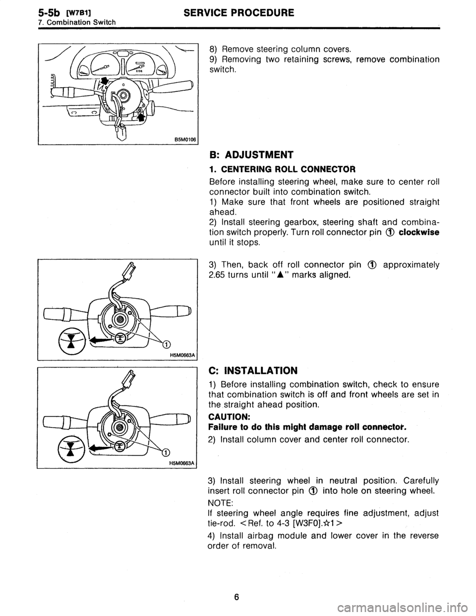
Turn
roll
connector
pin
(J)
clockwise
until
it
stops
.
3)
Then,
back
off
roll
connector
pin
1~
approximately
2
.65
turns
until
"A"
marks
aligned
.
C
:
INSTALLATION
1)
Before
installing
combination
switch,
check
to
ensure
that
combination
switch
is
off
and
font
wheels
are
set
in
the
.straight
ahead
position
.
CAUTION
:
Failure
to
do
this
might
damage
roll
connoctok
.
2)
Install
column
cover
and
center
roll
connector
.
3)
Install
steering
wheel
in
neutral
position
.
Carefully
insert
roll
connector
pin
1(~
into
hole
on
steering
wheel
.
NOTE
:
If
steering
wheel
angle
requires
fine
adjustment,
adjust
tie-rod
.
<
Ref
.
to
4-3
[W3FOj
.*1
>
4)
Install
airbag
module
and
lower
cover
in
the
reverse
order
of
removal
.
6
Page 147 of 2890
![SUBARU LEGACY 1996 Service Repair Manual
5-5b
[TaAO]
SUPPLEMENTAL
RESTRAINT
SYSTEM
(ELECTRIC
SENSOR
TYPE)
4
.
Diagnostics
Chart
for
On-board
Diagnostic
System
4
.
Diagnostics
Chart
for
On-board
Diagnostic
System
A
:
BASIC
DIAGNOSTICS
PR SUBARU LEGACY 1996 Service Repair Manual
5-5b
[TaAO]
SUPPLEMENTAL
RESTRAINT
SYSTEM
(ELECTRIC
SENSOR
TYPE)
4
.
Diagnostics
Chart
for
On-board
Diagnostic
System
4
.
Diagnostics
Chart
for
On-board
Diagnostic
System
A
:
BASIC
DIAGNOSTICS
PR](/manual-img/17/57433/w960_57433-146.png)
5-5b
[TaAO]
SUPPLEMENTAL
RESTRAINT
SYSTEM
(ELECTRIC
SENSOR
TYPE)
4
.
Diagnostics
Chart
for
On-board
Diagnostic
System
4
.
Diagnostics
Chart
for
On-board
Diagnostic
System
A
:
BASIC
DIAGNOSTICS
PROCEDURE
1)
Airbag
warning
light
comes
"ON"
.
2)
Turn
ignition
switch
to
"ON",
(engine
"OFF")
and
observe
airbag
warning
light
.
3)
If
airbag
warning
light
stays
"ON"
after
8
seconds
or
remains
"OFF",
or
comes
back
"ON"
after
30
seconds,
this
indicates
a
current
problem
.
Proceed
to
step
8)
.
If
airbag
warning
light
comes
"ON"
for
8
seconds,
then
goes
out
and
stays
out,
this
indicates
normalsystem
operation
atthis
time
.
Check
the
memory
for
intermittent
problems
by
performing
the
procedure
outlined
in
[T4B0)tr2
"ON-BOARD
DIAGNOSTICS"
.
Proceed
to
step
4)
.
4)
If
trouble
code
indicated,
<
Ref
.
to
[T4D1]*2
-
[T4D2]
.*2>
proceed
to
step
5)
.
If
normal
code
indicated,
<
Ref
.
to
[T4D2]
.
>
proceed
to
step
6)
.
5)
Repairand
replacement,
<
Ref
.
to
[T5P1]
.*2>
proceed
to
step
7)
.
6)
Repair
and
replacement,
<
Ref
.
to
[T5Q1]
.*2>
proceed
to
step
7)
.
7)
Turn
ignition
switch
"ON",
(engine
"OFF")
and
observe
airbag
warning
light
.
If
airbag
warning
light
stays
"ON"
after
8
seconds
or
comes
back
"ON"
after
30
seconds,
proceed
to
step
8)
.
If
airbag
warning
light
comes
"ON"
for
8
seconds,
then
goes
out
and
stays
out,
proceed
to
step
9)
.
8)
Repair
and
replacement
.
<
Ref
.
to
[T4E1]
.*2>
Proceed
to
step
10)
.
9)
Clear
memory
.
<
Ref
.
to
[T4C0]
.z`r2>
Proceed
to
step
10)
.
10)
END
Page 148 of 2890
![SUBARU LEGACY 1996 Service Repair Manual
SUPPLEMENTAL
RESTRAINT
SYSTEM
(ELECTRIC
SENSOR
TYPE)
[T4CO]
5-5b
4
.
Diagnostics
Chart
for
On-board
Diagnostic
System
2
L3141
B5mol
15B
2
33
E
;1
1~3141516
B5M01
16B
B
:
ON-BOARD
DIAGNOSTIC
W SUBARU LEGACY 1996 Service Repair Manual
SUPPLEMENTAL
RESTRAINT
SYSTEM
(ELECTRIC
SENSOR
TYPE)
[T4CO]
5-5b
4
.
Diagnostics
Chart
for
On-board
Diagnostic
System
2
L3141
B5mol
15B
2
33
E
;1
1~3141516
B5M01
16B
B
:
ON-BOARD
DIAGNOSTIC
W](/manual-img/17/57433/w960_57433-147.png)
SUPPLEMENTAL
RESTRAINT
SYSTEM
(ELECTRIC
SENSOR
TYPE)
[T4CO]
5-5b
4
.
Diagnostics
Chart
for
On-board
Diagnostic
System
2
L3141
B5mol
15B
2
33
E
;1
1~3141516
B5M01
16B
B
:
ON-BOARD
DIAGNOSTIC
When
the
airbag
system
isin
functioning
condition,
the
airbag
warning
light
will
remain
on
for
8
seconds
and
go
out
when
the
ignition
switch
is
set
to
ON
.
If
there
is
any
malfunction,
the
airbag
warning
light
will
either
stay
on
or
off
continuously
.
In
such
cases,
perform
on-board
diagnostic
in
accordance
with
the
specified
pro-
cedure
to
determine
trouble
codes
.
1)
Turn
ignition
switch
ON
(with
engine
OFF)
.
2)
ConnectDIAG
.
terminal
T
to
No
.
1
terminal
of
diag-
nosis
connector
~2
located
below
lower
cover
.
3)
Check
in
accordance
with
the
trouble
code
indicated
by
the
AIRBAG
warning
light,
and
record
the
trouble
codes
.
4)
Turn
the
ignition
switch
"OFF"
and
remove
the
DIAL
.
terminal
from
No
.1
terminal
of
diagnosis
connector
.
C
:
CLEAR
MEMORY
After
eliminating
problem
as
per
trouble
code,
clear
mem-
oryas
follows
:
Make
sure
ignition
switch
is
ON
(and
engine
off)
.
Connect
one
DIAL
.
terminal
1Q
on
diagnosis
connector
(Z
termi-
nal
No
.
1
.
While
warning
light
is
flashing,
connect
the
other
DIAL
.
terminal
(Z
on
terminal
No
.
2
for
at
least
three
seconds
.
After
memory
is
cleared,
normal
warning
light
flashing
rate
resumes
.
(Warning
light
flashes
every
0
.6
seconds
ON-OFF
operation
.)
Memory
cannotbe
cleared
if
any
problem
exists
.
After
clear
memory
and
then
DIAG
.
terminals
(1)
and
(3),
extract
from
diagnosis
connector
02
.
9
Page 150 of 2890
![SUBARU LEGACY 1996 Service Repair Manual
SUPPLEMENTAL
RESTRAINT
SYSTEM
(ELECTRIC
SENSOR
TYPE)
[TaD2]
5-5b
4
.
Diagnostics
Chart
for
On-board
Diagnostic
System
Trouble
code/Contents
of
troubles
Memory
function
Contents
of
diagnosis
Page
1 SUBARU LEGACY 1996 Service Repair Manual
SUPPLEMENTAL
RESTRAINT
SYSTEM
(ELECTRIC
SENSOR
TYPE)
[TaD2]
5-5b
4
.
Diagnostics
Chart
for
On-board
Diagnostic
System
Trouble
code/Contents
of
troubles
Memory
function
Contents
of
diagnosis
Page
1](/manual-img/17/57433/w960_57433-149.png)
SUPPLEMENTAL
RESTRAINT
SYSTEM
(ELECTRIC
SENSOR
TYPE)
[TaD2]
5-5b
4
.
Diagnostics
Chart
for
On-board
Diagnostic
System
Trouble
code/Contents
of
troubles
Memory
function
Contents
of
diagnosis
Page
1)
Airbag
warning
light
is
faulty
.
2)
Airbag
control
module
to
airbag
warning
light
Airbag
warning
light
remains
on
.
Not
provided
.
harness
circuit
is
shorted
or
open
.
32
3)
Grounding
circuit
is
faulty
.
4)
Airbag
control
module
is
faulty
.
5)
(AB1)
and
(B39)arenot
connected
properly
.
1)
Fuse
No
.
15
is
blown
.
2)
Body
harness
circuit
is
open
.
Airbag
warning
light
remains
off
.
Not
provided
.
3)
Airbag
warning
light
is
faulty
.
35
4)
Airbag
main
harness
is
faulty
.
5)
Airbag
control
module
is
faulty
.
Warning
light
indicates
trouble
code,
then
normal
code
.
(Flashing
trouble
Provided
.
Airbag
system
component
parts
are
faulty
.
38
code
.)
1)
Airbag
connector
is
faulty
.
Warning
light
indicates
trouble
code,
2)
Fuse
No
.
16
is
blown
.
then
normal
code
.
(Flashing
normal
Not
provided
.
3)
Airbag
main
harness
is
faulty
.
41
code
.)
4)
Airbag
control
module
is
faulty
.
5)
Body
harness
is
faulty
.
[NOTE]
Dr
:
Driver
side
Ps
:
Passenger
side
2
.
HOW
TOREAD
TROUBLE
CODES
TheAIRBAG
warning
light
flashes
a
code
corresponding
to
the
faulty
parts
.
The
long
segment
(1.2
secon)
indicates
a
"ten",
and
the
short
segment
(0
.3
secon)
indicates
a
"one"
.
Example
:
ON
Flashing10
111
p
~
J
~
L
J
1
code
12
:
OFF
1
.2
0
.3
0
.3
0
.3
0
.3
1
2
(Sec)
ON
Flashing
OFF
10
10
70
.3171d
.2
_
11
10
code
21
:
T
12
0
.3
1
.2
0
.3
(Sec)
Flashing
ON
normal
OFF
code
:
1
0
.6
0
.6
(Sec)
85M01
17A
11
Page 151 of 2890

5-5b
[TaE1)
SUPPLEMENTAL
RESTRAINT
SYSTEM
(ELECTRIC
SENSOR
TYPE)
4
.
DiagnosticsChart
for
On-board
Diagnostic
System
E
:
DIAGNOSTICS
PROCEDURE
1
.
AIRBAG
WARNING
LIGHT
STAYS
ON
AFTER
8
SECONDS
.
1)
Perform
on-board
diagnostic
.
<
Ref
.
to
5-5
[T4130]
.
*2>
2)
Are
trouble
codes
4,
12,
13,
22,
34,
41,
42
or
43
indi-
cated?
<
Ref
.
to
5-5
[T4D1
]*2-[T4D2]
.*2
>
Record
trouble
codes
.
If
"YES"
proceed
to
step
4)
.
If
"NO"
proceed
to
step
3)
.
3)
Proceed
with
diagnostics
and
repair
according
to
trou-
ble
code
indicated
then
perform
step
15)
.
4)
If
codes
4,
22,34,
42are
indicated,
proceed
tostep
5)
.
If
codes
4,
22,
34,
42
arenot
indicated,
proceed
to
step
10)
.
5)
If
codes
12,
13,
41,
43
are
indicated,
proceed
tostep
6)
.
If
codes
12,13,41,
43are
not
indicated,
proceed
to
step
11)
.
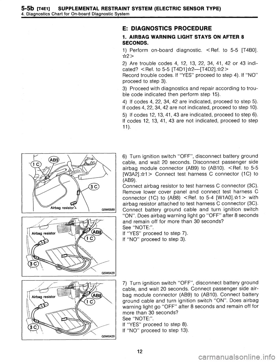
6)
Turn
ignition
switch
"OFF",
disconnect
battery
ground
cable,
and
wait
20
seconds
.
Disconnect
passenger
side
airbag
module
connector
(AB9)
to
(AB10)
.
<
Ref
.
to
5-5
[W3A2]
.*1
>
Connect
test
harness
C
connector
(1
C)
to
(AB9)
.
Connect
airbag
resistorto
test
harness
C
connector
(3C)
.
Remove
lower
coverpanel
and
connect
test
harness
C
connector
(1C)
to
(AB8)
<
Ref
.
to
5-4
[W1A0)
.*1
>
with
airbag
resistor
attached
to
test
harness
C
connector
(3C)
.
Connect
battery
ground
cable
and
turn
ignition
switch
"ON"
.
Does
airbag
warning
light
go
"OFF"
after
8
seconds
and
remain
off
for
more
than
30
seconds?
See
"NOTE
:"
.
If
"YES"
proceed
tostep
7)
.
If
"NO"
proceed
tostep
3)
.
7)
Turn
ignition
switch
"OFF",
disconnect
battery
ground
cable,
and
wait
20
seconds
.
Connect
passenger
side
air-
bagmodule
connector
(AB9)
to
(AB10)
.
Connect
battery
ground
cable
and
turn
ignition
switch
"ON"
.
Does
airbag
warning
light
go
"OFF"
after
8
seconds
and
remain
offfor
more
than
30
seconds?
See
"NOTE
:"
.
If
"YES"
proceed
to
step
8)
.
If
"NO"
proceed
tostep
13)
.
12