Page 170 of 2890
![SUBARU LEGACY 1996 Service Repair Manual
SUPPLEMENTAL
RESTRAINT
SYSTEM
(ELECTRIC
SENSOR
TYPE)
[T5(a1]
5-5b
5
.
Diagnostics
Chart
with
Trouble
Code
Q
:
WARNING
LIGHTINDICATES
TROUBLE
CODE,
THEN
NORMAL
CODE
.
-
FLASHING
NORMAL
CODE
.
-
D SUBARU LEGACY 1996 Service Repair Manual
SUPPLEMENTAL
RESTRAINT
SYSTEM
(ELECTRIC
SENSOR
TYPE)
[T5(a1]
5-5b
5
.
Diagnostics
Chart
with
Trouble
Code
Q
:
WARNING
LIGHTINDICATES
TROUBLE
CODE,
THEN
NORMAL
CODE
.
-
FLASHING
NORMAL
CODE
.
-
D](/manual-img/17/57433/w960_57433-169.png)
SUPPLEMENTAL
RESTRAINT
SYSTEM
(ELECTRIC
SENSOR
TYPE)
[T5(a1]
5-5b
5
.
Diagnostics
Chart
with
Trouble
Code
Q
:
WARNING
LIGHTINDICATES
TROUBLE
CODE,
THEN
NORMAL
CODE
.
-
FLASHING
NORMAL
CODE
.
-
DIAGNOSIS
:
"
Airbag
connector
is
faulty
.
"
Fuse
No
.
16
is
blown
.
"
Airbag
.
main
harness
is
faulty
.
"
Airbag
control
module
is
faulty
.
"
Body
harness
is
faulty
.
1
1
.
Airbag
connector
appearance
inspection
1
2
.
Atrbag
connector
vibration
inspection
3
.
Showering
inspection
to
body
4
.
Fuse
No
.
16,
airbag
main
harness,
airbag
control
module,
body
harness
appearance
inspection
5
.
Fuse
No
.
16,
airbag
main
harness,
body
harness
vibration
inspection
1
6
.
Showering
inspectionto
body
1
7
.
Warning
light
illumination
check
CAUTION
:
Before
performing
diagnostics
on
airbag
system,
turn
ignition
switch
"OFF",
disconnect
battery
ground
cable,
and
then
wait
at
least
20
seconds
.
1
.
AIRBAG
CONNECTOR
APPEARANCE
INSPECTION
Conduct
appearance
inspection
on
airbag
connectors
(AB2)
through
(AB8)
.
<
Ref
.
to
5-5
[T100]
.*2
>
CHECK
:
Is
thereanything
unusualabout
the
appear-
ance
of
connectors(AB2)
through
(AB8)?
,rES
:
Replace
faulty
airbag
component
parts
.
No
:
Go
to
step
2
.
NOTE
:
Check
terminals,
case
and
wiring
harnesses
for
damage
.
41
Page 172 of 2890
![SUBARU LEGACY 1996 Service Repair Manual
SUPPLEMENTAL
RESTRAINT
SYSTEM
(ELECTRIC
SENSOR
TYPE)
[T5G17]
5-5b
5
.
Diagnostics
Chart
with
Trouble
Code
v
0
v
GSM0461
5
.
FUSENo
.
16,
AIRBAG
MAINHARNESS,
BODY
HARNESS
VIBRATION
INSPECTION
Co SUBARU LEGACY 1996 Service Repair Manual
SUPPLEMENTAL
RESTRAINT
SYSTEM
(ELECTRIC
SENSOR
TYPE)
[T5G17]
5-5b
5
.
Diagnostics
Chart
with
Trouble
Code
v
0
v
GSM0461
5
.
FUSENo
.
16,
AIRBAG
MAINHARNESS,
BODY
HARNESS
VIBRATION
INSPECTION
Co](/manual-img/17/57433/w960_57433-171.png)
SUPPLEMENTAL
RESTRAINT
SYSTEM
(ELECTRIC
SENSOR
TYPE)
[T5G17]
5-5b
5
.
Diagnostics
Chart
with
Trouble
Code
v
0
v
GSM0461
5
.
FUSENo
.
16,
AIRBAG
MAINHARNESS,
BODY
HARNESS
VIBRATION
INSPECTION
Conduct
vibration
inspection
on
fuse
No
.
16,
airbag
main
harness
and
body
harness
.
CAUTION
:
Do
not
shake
or
vibrate
airbag
control
module
.
CHECK
:
Do
fuse
No
.
16,
airbag
main
harness
or
body
harness
malfunction
again
when
shaking?
Replace
faulty
airbag
component
parts
.
No
:
Go
to
step
6
.
NOTE
:
Gently
shake
each
part
.
6
.
SHOWERING
INSPECTION
TO
BODY
Spray
water
on
vehicle
body
.
CAUTION
:
Do
not
directly
spraywater
on
each
part
.
CHECK
:
Does
wafer
leak
into
the
passenger
compart-
ment
when
showering
vehicle?
,res
:
Replace
faulty
airbag
component
parts
.
No
:
Go
to
step
7
.
NOTE
:
If
leaks
are
noted,
check
wiring
harnesses
as
water
may
leak
along
them
and
get
parts
wet
.
7
.
WARNING
LIGHT
ILLUMINATION
CHECK
Turn
ignition
switch
"ON"
(engine
off)
and
observe
airbag
warning
light
.
CHECK
:
Does
the
airbag
warning
light
comes
on
for
8
seconds,then
go
out
and
stay
out?
,rES
:
Clear
memory
.
Go
to
[T4E0]*2
"DIAGNOSTICS
PROCEDURE"
.
43
Page 1572 of 2890
G5M0291
1. Precaution
1) If any of the airbag system parts such as sensors, air-
bag module, airbag control module and harness are dam-
aged or deformed, replace with new genuine parts.
G5M0292
2) When servicing, be sure to turn the ignition switch off,
disconnect the negative (�) battery terminal then the posi-
tive (+) terminal in advance, and wait for more than 20
seconds before starting work.
G5M0293
3) When checking the system, be sure to use a digital cir-
cuit tester. Use of an analog circuit tester may cause the
airbag to activate erroneously. Do not directly apply the
tester probe to any connector terminal of the airbag. When
checking, use a test harness.
G5M0294
4
5-5SERVICE PROCEDURE
1. Precaution
Page 1574 of 2890

G5M0298
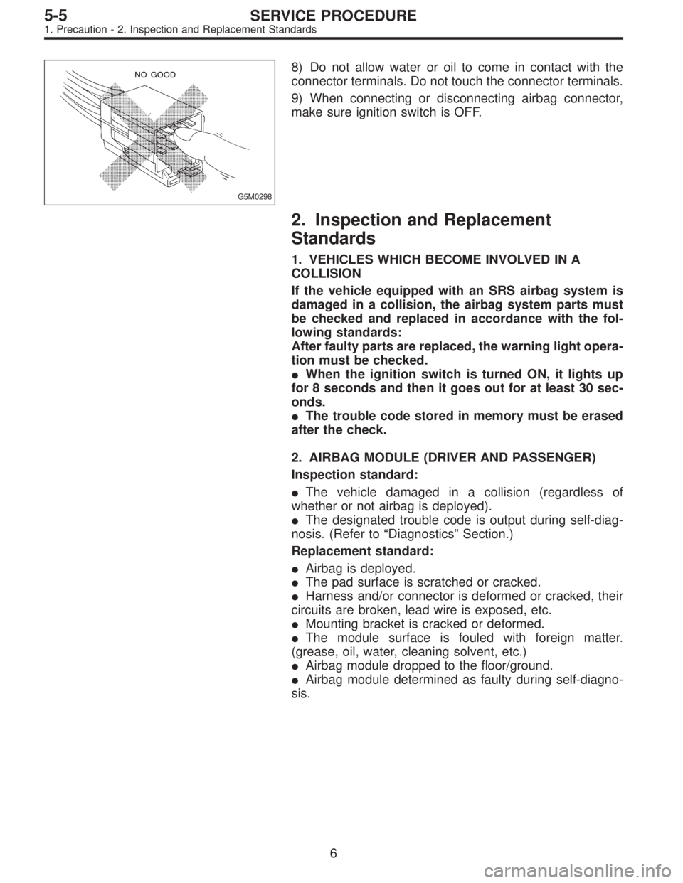
8) Do not allow water or oil to come in contact with the
connector terminals. Do not touch the connector terminals.
9) When connecting or disconnecting airbag connector,
make sure ignition switch is OFF.
2. Inspection and Replacement
Standards
1. VEHICLES WHICH BECOME INVOLVED IN A
COLLISION
If the vehicle equipped with an SRS airbag system is
damaged in a collision, the airbag system parts must
be checked and replaced in accordance with the fol-
lowing standards:
After faulty parts are replaced, the warning light opera-
tion must be checked.
�When the ignition switch is turned ON, it lights up
for 8 seconds and then it goes out for at least 30 sec-
onds.
�The trouble code stored in memory must be erased
after the check.
2. AIRBAG MODULE (DRIVER AND PASSENGER)
Inspection standard:
�The vehicle damaged in a collision (regardless of
whether or not airbag is deployed).
�The designated trouble code is output during self-diag-
nosis. (Refer to“Diagnostics”Section.)
Replacement standard:
�Airbag is deployed.
�The pad surface is scratched or cracked.
�Harness and/or connector is deformed or cracked, their
circuits are broken, lead wire is exposed, etc.
�Mounting bracket is cracked or deformed.
�The module surface is fouled with foreign matter.
(grease, oil, water, cleaning solvent, etc.)
�Airbag module dropped to the floor/ground.
�Airbag module determined as faulty during self-diagno-
sis.
6
5-5SERVICE PROCEDURE
1. Precaution - 2. Inspection and Replacement Standards
Page 1575 of 2890

G5M0298
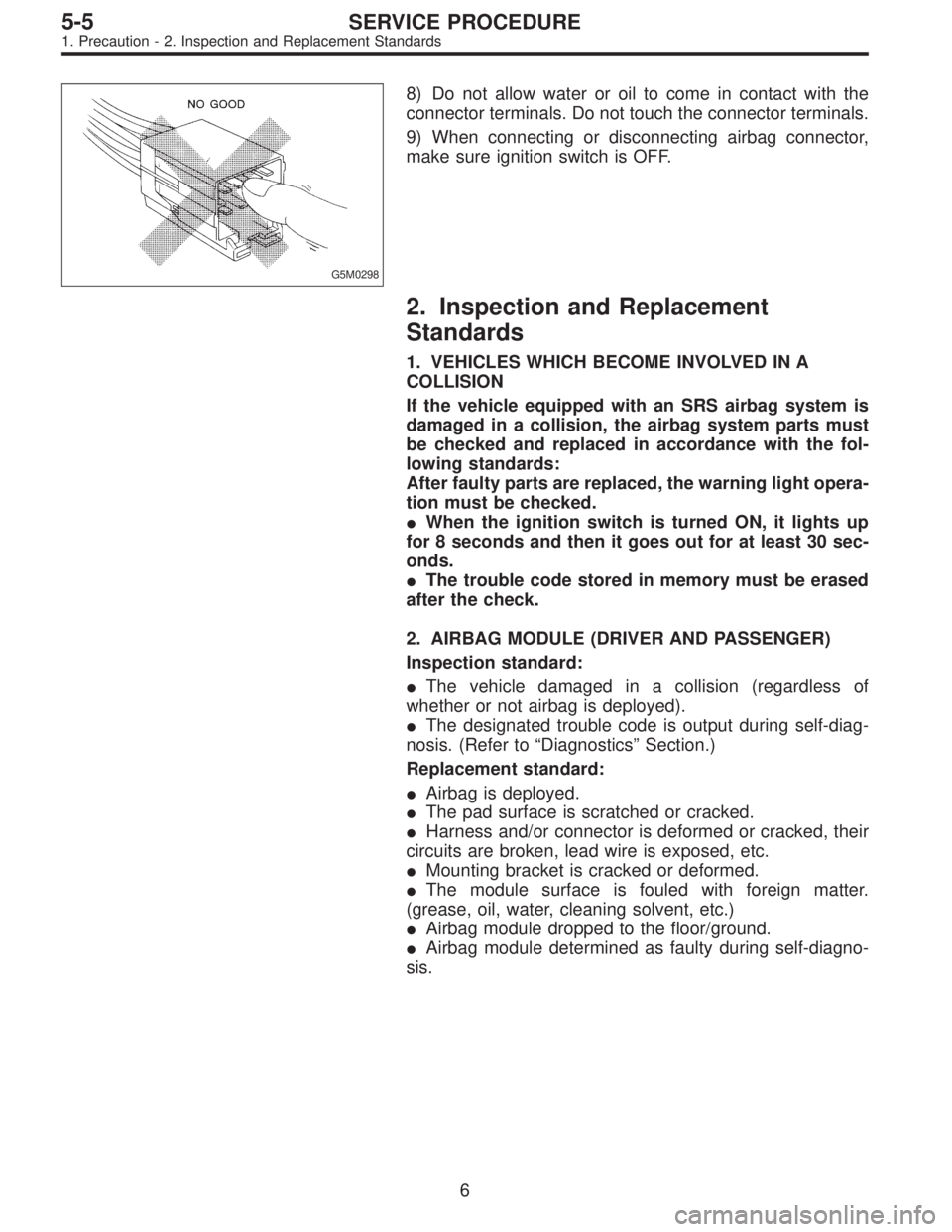
8) Do not allow water or oil to come in contact with the
connector terminals. Do not touch the connector terminals.
9) When connecting or disconnecting airbag connector,
make sure ignition switch is OFF.
2. Inspection and Replacement
Standards
1. VEHICLES WHICH BECOME INVOLVED IN A
COLLISION
If the vehicle equipped with an SRS airbag system is
damaged in a collision, the airbag system parts must
be checked and replaced in accordance with the fol-
lowing standards:
After faulty parts are replaced, the warning light opera-
tion must be checked.
�When the ignition switch is turned ON, it lights up
for 8 seconds and then it goes out for at least 30 sec-
onds.
�The trouble code stored in memory must be erased
after the check.
2. AIRBAG MODULE (DRIVER AND PASSENGER)
Inspection standard:
�The vehicle damaged in a collision (regardless of
whether or not airbag is deployed).
�The designated trouble code is output during self-diag-
nosis. (Refer to“Diagnostics”Section.)
Replacement standard:
�Airbag is deployed.
�The pad surface is scratched or cracked.
�Harness and/or connector is deformed or cracked, their
circuits are broken, lead wire is exposed, etc.
�Mounting bracket is cracked or deformed.
�The module surface is fouled with foreign matter.
(grease, oil, water, cleaning solvent, etc.)
�Airbag module dropped to the floor/ground.
�Airbag module determined as faulty during self-diagno-
sis.
6
5-5SERVICE PROCEDURE
1. Precaution - 2. Inspection and Replacement Standards
Page 1581 of 2890
A: REMOVAL
1. DRIVER SIDE
1) Set front wheels in straight ahead position.
2) Turn ignition switch off.
3) Disconnect ground cable from battery and wait for at
least 20 seconds before starting work.
H5M0662A
4) Using TORX®BIT T30, remove two TORX®bolts.
H5M0664
5) Disconnect airbag connector on back of airbag module.
6) Refer to“CAUTION”for handling of a removed airbag
module.
2. PASSENGER SIDE
1) Remove instrument panel.
12
5-5SERVICE PROCEDURE
3. Airbag Module
Page 1582 of 2890

B5M0098
2) Remove four bolts and then carefully remove airbag
module.
3) Refer to“CAUTION”for handling of a removed airbag
module.
B: INSTALLATION
Installation is in reverse order of removal procedures.
Observe the following: Make sure that ignition switch is off.
CAUTION:
Do not allow harness and connectors to interfere or
get caught with other parts.
G5M0291
4. Front Sensor
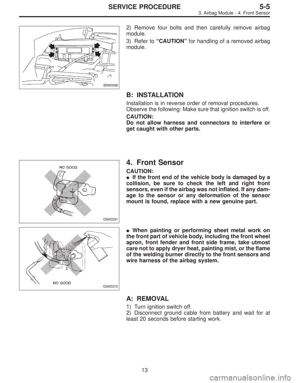
CAUTION:
�If the front end of the vehicle body is damaged by a
collision, be sure to check the left and right front
sensors, even if the airbag was not inflated. If any dam-
age to the sensor or any deformation of the sensor
mount is found, replace with a new genuine part.
G5M0310
�When painting or performing sheet metal work on
the front part of vehicle body, including the front wheel
apron, front fender and front side frame, take utmost
care not to apply dryer heat, painting mist, or the flame
of the welding burner directly to the front sensors and
wire harness of the airbag system.
A: REMOVAL
1) Turn ignition switch off.
2) Disconnect ground cable from battery and wait for at
least 20 seconds before starting work.
13
5-5SERVICE PROCEDURE
3. Airbag Module - 4. Front Sensor
Page 1583 of 2890

B5M0098
2) Remove four bolts and then carefully remove airbag
module.
3) Refer to“CAUTION”for handling of a removed airbag
module.
B: INSTALLATION
Installation is in reverse order of removal procedures.
Observe the following: Make sure that ignition switch is off.
CAUTION:
Do not allow harness and connectors to interfere or
get caught with other parts.
G5M0291
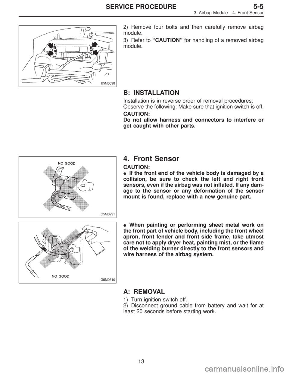
4. Front Sensor
CAUTION:
�If the front end of the vehicle body is damaged by a
collision, be sure to check the left and right front
sensors, even if the airbag was not inflated. If any dam-
age to the sensor or any deformation of the sensor
mount is found, replace with a new genuine part.
G5M0310
�When painting or performing sheet metal work on
the front part of vehicle body, including the front wheel
apron, front fender and front side frame, take utmost
care not to apply dryer heat, painting mist, or the flame
of the welding burner directly to the front sensors and
wire harness of the airbag system.
A: REMOVAL
1) Turn ignition switch off.
2) Disconnect ground cable from battery and wait for at
least 20 seconds before starting work.
13
5-5SERVICE PROCEDURE
3. Airbag Module - 4. Front Sensor