Page 1613 of 2890
H5M0664
6) Disconnect airbag connector on back of airbag module.
Remove airbag module, and place it
with pad side facing upward.
G5M0332
7) Using steering puller, remove steering wheel.
CAUTION:
Do not allow connector to interfere when removing
steering wheel.
B5M0106
8) Remove steering column covers.
9) Removing two retaining screws, remove combination
switch.
B: ADJUSTMENT
1. CENTERING ROLL CONNECTOR
Before installing steering wheel, make sure to center roll
connector built into combination switch.
1) Make sure that front wheels are positioned straight
ahead.
2) Install steering gearbox, steering shaft and combination
switch properly. Turn roll connector pin�
1clockwiseuntil
it stops.
H5M0663A
3) Then, back off roll connector pin�1approximately 2.65
turns until“�”marks aligned.
17
5-5bSERVICE PROCEDURE
6. Combination Switch
Page 1614 of 2890
H5M0663A
C: INSTALLATION
1) Before installing combination switch, check to ensure
that combination switch is off and front wheels are set in
the straight ahead position.
CAUTION:
Failure to do this might damage roll connector.
2) Install column cover and center roll connector.
3) Install steering wheel in neutral position. Carefully insert
roll connector pin�
1into hole on steering wheel.
NOTE:
If steering wheel angle requires fine adjustment, adjust tie-
rod.
4) Install airbag module and lower cover in the reverse
order of removal.
18
5-5bSERVICE PROCEDURE
6. Combination Switch
Page 1657 of 2890
1. Precaution
�Before disassembling or reassembling parts, always
disconnect battery ground cable. When repairing
radio, control modules, etc. which are provided with
memory functions, record memory contents before
disconnecting battery ground cable. Otherwise, these
contents are cancelled upon disconnection.
�Reassemble parts in reverse order of disassembly
procedure unless otherwise indicated.
�Adjust parts to specifications contained in this
manual if so designated.
�Connect connectors and hoses securely during
reassembly.
�After reassembly, ensure functional parts operate
smoothly.
CAUTION:
�Airbag system wiring harness is routed near the
electrical parts and switch.
�All Airbag system wiring harness and connectors
are colored yellow. Do not use electrical test equip-
ment on these circuit.
�Be careful not to damage Airbag system wiring har-
ness when servicing the ignition key cylinder.
G6M0102
2. Battery
A: REMOVAL AND INSTALLATION
1. BATTERY
1) Disconnect the positive (+) terminal after disconnecting
the negative (�) terminal of battery.
2) Remove flange nuts from battery rods and take off bat-
tery holder.
3) Remove battery.
Tightening torque:
3.4±1.0 N⋅m (0.35±0.1 kg-m, 2.5±0.7 ft-lb)
NOTE:
�Clean battery cable terminals and apply grease to retard
the formation of corrosion.
�Connect the positive (+) terminal of battery and then the
negative (�) terminal of the battery.
4
6-2SERVICE PROCEDURE
1. Precaution - 2. Battery
Page 1658 of 2890
1. Precaution
�Before disassembling or reassembling parts, always
disconnect battery ground cable. When repairing
radio, control modules, etc. which are provided with
memory functions, record memory contents before
disconnecting battery ground cable. Otherwise, these
contents are cancelled upon disconnection.
�Reassemble parts in reverse order of disassembly
procedure unless otherwise indicated.
�Adjust parts to specifications contained in this
manual if so designated.
�Connect connectors and hoses securely during
reassembly.
�After reassembly, ensure functional parts operate
smoothly.
CAUTION:
�Airbag system wiring harness is routed near the
electrical parts and switch.
�All Airbag system wiring harness and connectors
are colored yellow. Do not use electrical test equip-
ment on these circuit.
�Be careful not to damage Airbag system wiring har-
ness when servicing the ignition key cylinder.
G6M0102
2. Battery
A: REMOVAL AND INSTALLATION
1. BATTERY
1) Disconnect the positive (+) terminal after disconnecting
the negative (�) terminal of battery.
2) Remove flange nuts from battery rods and take off bat-
tery holder.
3) Remove battery.
Tightening torque:
3.4±1.0 N⋅m (0.35±0.1 kg-m, 2.5±0.7 ft-lb)
NOTE:
�Clean battery cable terminals and apply grease to retard
the formation of corrosion.
�Connect the positive (+) terminal of battery and then the
negative (�) terminal of the battery.
4
6-2SERVICE PROCEDURE
1. Precaution - 2. Battery
Page 1835 of 2890
4. Cautions
A: SUPPLEMENTAL RESTRAINT SYSTEM
“AIRBAG”
Airbag system wiring harness is routed near the engine
control module (ECM), main relay and fuel pump relay.
CAUTION:
�All Airbag system wiring harness and connectors
are colored yellow. Do not use electrical test equip-
ment on these circuit.
�Be careful not to damage Airbag system wiring har-
ness when servicing the engine control module (ECM),
transmission control module (TCM), main relay and
fuel pump relay.
B: PRECAUTIONS
1) Never connect the battery in reverse polarity.
�The ECM will be destroyed instantly.
�The fuel injector and other part will be damaged in just
a few minutes more.
2) Do not disconnect the battery terminals while the
engine is running.
�A large counter electromotive force will be generated in
the alternator, and this voltage may damage electronic
parts such as ECM, etc.
3) Before disconnecting the connectors of each sensor
and the ECM, be sure to turn OFF the ignition switch.
4) Before removing ECM from the located position, dis-
connect two cables on battery.
�Otherwise, the ECM may be damaged.
5) The connectors to each sensor in the engine compart-
ment and the harness connectors on the engine side and
body side are all designed to be waterproof. However, it is
still necessary to take care not to allow water to get into the
connectors when washing the vehicle, or when servicing
the vehicle on a rainy day.
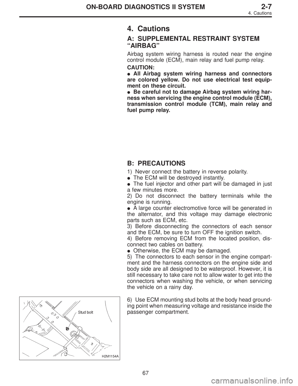
H2M1154A
6) Use ECM mounting stud bolts at the body head ground-
ing point when measuring voltage and resistance inside the
passenger compartment.
67
2-7ON-BOARD DIAGNOSTICS II SYSTEM
4. Cautions
Page 2621 of 2890
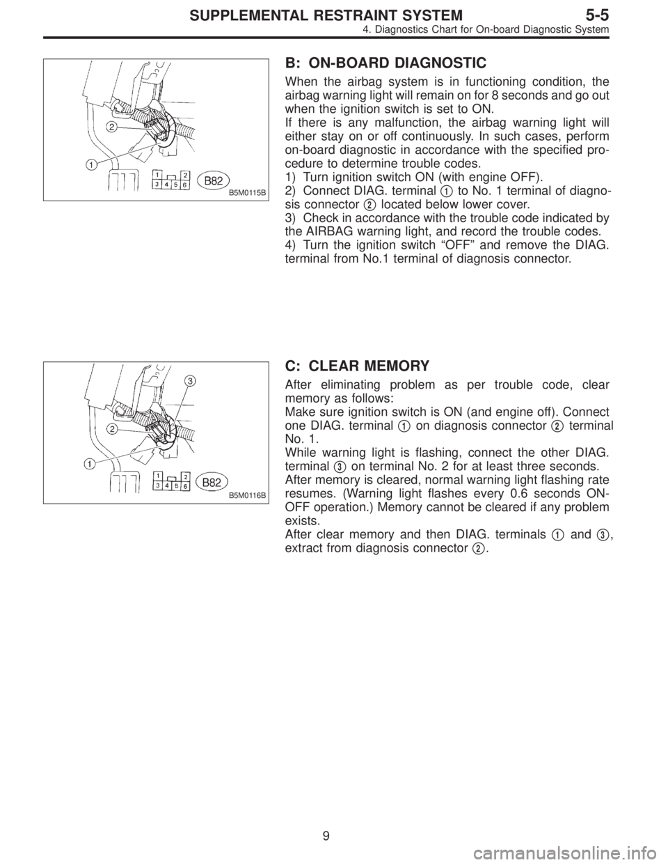
B5M0115B
B: ON-BOARD DIAGNOSTIC
When the airbag system is in functioning condition, the
airbag warning light will remain on for 8 seconds and go out
when the ignition switch is set to ON.
If there is any malfunction, the airbag warning light will
either stay on or off continuously. In such cases, perform
on-board diagnostic in accordance with the specified pro-
cedure to determine trouble codes.
1) Turn ignition switch ON (with engine OFF).
2) Connect DIAG. terminal�
1to No. 1 terminal of diagno-
sis connector�
2located below lower cover.
3) Check in accordance with the trouble code indicated by
the AIRBAG warning light, and record the trouble codes.
4) Turn the ignition switch “OFF” and remove the DIAG.
terminal from No.1 terminal of diagnosis connector.
B5M0116B
C: CLEAR MEMORY
After eliminating problem as per trouble code, clear
memory as follows:
Make sure ignition switch is ON (and engine off). Connect
one DIAG. terminal�
1on diagnosis connector�2terminal
No. 1.
While warning light is flashing, connect the other DIAG.
terminal�
3on terminal No. 2 for at least three seconds.
After memory is cleared, normal warning light flashing rate
resumes. (Warning light flashes every 0.6 seconds ON-
OFF operation.) Memory cannot be cleared if any problem
exists.
After clear memory and then DIAG. terminals�
1and�3,
extract from diagnosis connector�
2.
9
5-5SUPPLEMENTAL RESTRAINT SYSTEM
4. Diagnostics Chart for On-board Diagnostic System
Page 2623 of 2890
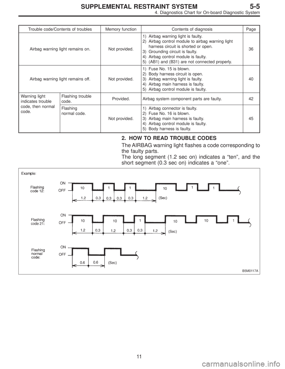
Trouble code/Contents of troubles Memory function Contents of diagnosis Page
Airbag warning light remains on. Not provided.1) Airbag warning light is faulty.
2) Airbag control module to airbag warning light
harness circuit is shorted or open.
3) Grounding circuit is faulty.
4) Airbag control module is faulty.
5) (AB1) and (B31) are not connected properly.36
Airbag warning light remains off. Not provided.1) Fuse No. 15 is blown.
2) Body harness circuit is open.
3) Airbag warning light is faulty.
4) Airbag main harness is faulty.
5) Airbag control module is faulty.40
Warning light
indicates trouble
code, then normal
code.Flashing trouble
code.Provided. Airbag system component parts are faulty. 42
Flashing
normal code.
Not provided.1) Airbag connector is faulty.
2) Fuse No. 16 is blown.
3) Airbag main harness is faulty.
4) Airbag control module is faulty.
5) Body harness is faulty.45
2. HOW TO READ TROUBLE CODES
The AIRBAG warning light flashes a code corresponding to
the faulty parts.
The long segment (1.2 sec on) indicates a“ten”, and the
short segment (0.3 sec on) indicates a“one”.
B5M0117A
11
5-5SUPPLEMENTAL RESTRAINT SYSTEM
4. Diagnostics Chart for On-board Diagnostic System
Page 2624 of 2890
![SUBARU LEGACY 1996 Service Repair Manual E: DIAGNOSTICS PROCEDURE
Airbag warning light stays on after 8 seconds.
1) Perform on-board diagnostic. <Ref. to 5-5 [T4B0].>
2) Are trouble codes 2, 4, 12, 13, 22, 23, 24 or 32 indicated? <Ref. to 5- SUBARU LEGACY 1996 Service Repair Manual E: DIAGNOSTICS PROCEDURE
Airbag warning light stays on after 8 seconds.
1) Perform on-board diagnostic. <Ref. to 5-5 [T4B0].>
2) Are trouble codes 2, 4, 12, 13, 22, 23, 24 or 32 indicated? <Ref. to 5-](/manual-img/17/57433/w960_57433-2623.png)
E: DIAGNOSTICS PROCEDURE
Airbag warning light stays on after 8 seconds.
1) Perform on-board diagnostic.
2) Are trouble codes 2, 4, 12, 13, 22, 23, 24 or 32 indicated?
Record trouble codes.
3) If“NO”, proceed with diagnostics and repair according to trouble code indicated then perform step 29).
4) If“YES”, proceed by turning ignition switch“OFF”, disconnect battery ground cable, and wait 20 seconds. If codes 12 or 13 are
indicated proceed to step 5). If codes 12 or 13 are not indicated proceed to step 6).
5) Remove driver side airbag module and connect test harness C
connector (1C) to (AB7).
Connect airbag resistor to test harness C connector (3C). Pro-
ceed to step 19).
G5M0430
6) If codes 4 or 22 are indicated, proceed to step 7). If codes 4 or 22 are not indicated proceed to step 11).
7) Turn ignition switch“OFF”, disconnect battery ground cable,
and wait 20 seconds. Disconnect passenger side airbag mod-
ule connector (AB9) to (AB10). Connect
test harness C connector (1C) to (AB9).
Connect airbag resistor to test harness C connector (3C).
B5M0118A
8) Reconnect battery ground cable and turn ignition switch“ON”, does airbag warning light go out after 8 seconds and remain“OFF”
for more than 30 seconds? See notes 1) and 2). (Refer to end of chart.)
9) If“YES”, turn ignition switch“OFF”, disconnect battery ground cable, and wait 20 seconds. Install a new passenger side airbag
module then proceed to step 29).
10) If“NO”proceed to step 1).
11) Remove lower cover panel and connect test harness C con-
nector (1C) to (AB8) with airbag resis-
tor attached to test harness C connector (3C).
Turn ignition switch“ON”. Does airbag warning light go“OFF”
after 8 seconds and remain off for more than 30 seconds?
See notes 1) and 2). (Refer to end of chart.)
If“YES”proceed to step 5).
If“NO”proceed to step 12).
G5M0429
12
5-5SUPPLEMENTAL RESTRAINT SYSTEM
4. Diagnostics Chart for On-board Diagnostic System