Page 540 of 2890
 Remove rear oxygen sensor.
CAUTION:
When removing rear oxygen sensor, do not force rear
oxygen sensor especially when exhaust pipe is cold,
otherwise it will damage exhaust pipe.
B2M0352A
B")
B2M0741
4) Remove rear oxygen sensor.
CAUTION:
When removing rear oxygen sensor, do not force rear
oxygen sensor especially when exhaust pipe is cold,
otherwise it will damage exhaust pipe.
B2M0352A
B: INSTALLATION
1. EXCEPT CALIFORNIA 2200 cc MODEL
1) Before installing rear oxygen sensor, apply anti-seize
compound only to threaded portion of rear oxygen sensor
to make the next removal easier.
Anti-seize compound:
SS-30 by JET LUBE
CAUTION:
Never apply anti-seize compound to protector of rear
oxygen sensor.
B2M0351
2) Install rear oxygen sensor.
Tightening torque:
21±3 N⋅m (2.1±0.3 kg-m, 15.2±2.2 ft-lb)
3) Connect connector of rear oxygen sensor.
4) Lower the vehicle.
B2M0742A
2. CALIFORNIA 2200 cc MODEL
1) Before installing rear oxygen sensor, apply anti-seize
compound only to threaded portion of rear oxygen sensor
to make the next removal easier.
Anti-seize compound:
SS-30 by JET LUBE
CAUTION:
Never apply anti-seize compound to protector of rear
oxygen sensor.
22
2-7SERVICE PROCEDURE
8. Rear Oxygen Sensor
Page 541 of 2890
B2M0741
2) Install rear oxygen sensor.
Tightening torque:
21±3 N⋅m (2.1±0.3 kg-m, 15.2±2.2 ft-lb)
3) Lower the vehicle.
4) Connect connector to rear oxygen sensor.
23
2-7SERVICE PROCEDURE
8. Rear Oxygen Sensor
Page 542 of 2890
 Disconnect connector from throttle position sensor.
2) Remove throttle position sensor holding screws, and
remove it.
3) Installation")
B2M0162
9. Throttle Position Sensor
A: REMOVAL AND INSTALLATION
1) Disconnect connector from throttle position sensor.
2) Remove throttle position sensor holding screws, and
remove it.
3) Installation is in the reverse order of removal.
Tightening torque:
2.2±0.2 N⋅m (0.22±0.02 kg-m, 1.6±0.1 ft-lb)
CAUTION:
When installing throttle position sensor, adjust to the
specified data.
B2M0163
B: ADJUSTMENT
1) Turn ignition switch to OFF.
2) Loosen throttle position sensor holding screws.
G2M0415
3) When using voltage meter;
(1) Take out ECM.
(2) Turn ignition switch to ON.
(3) Adjust throttle position sensor so that signal voltage
to ECM may be in specification.
Connector & Terminal / Specified voltage
(B84) No. 24 — (B84) No. 25 / 0.45 — 0.55 V
[Fully closed.]
(4) Tighten throttle position sensor holding screws.
G2M0096
4) When using Subaru Select Monitor;
(1) Connect Subaru Select Monitor to the data link con-
nector.
(2) Turn ignition switch to ON and SSM switch to ON.
(3) Select mode “F10”.
(4) Adjust throttle position sensor to specified data.
Condition / Specified data.
Throttle fully closed / 0.50 V
(5) Tighten throttle position sensor holding screws.
24
2-7SERVICE PROCEDURE
9. Throttle Position Sensor
Page 543 of 2890
G2M0416
10. Camshaft Position Sensor
A: REMOVAL AND INSTALLATION
1) Disconnect connector from camshaft position sensor.
G2M0417
2) Remove camshaft position sensor from camshaft sup-
port LH.
3) Installation is in the reverse order of removal.
Tightening torque:
6.4±0.5 N⋅m (0.65±0.05 kg-m, 4.7±0.4 ft-lb)
B2M0355
11. Pressure Sensor (AT model)
A: REMOVAL AND INSTALLATION
1) Disconnect connector from pressure sensor.
2) Disconnect hose from pressure sensor.
B2M0356
3) Remove pressure sensor from bracket.
4) Installation is in the reverse order of removal.
Tightening torque:
6.4±0.5 N⋅m (0.65±0.05 kg-m, 4.7±0.4 ft-lb)
25
2-7SERVICE PROCEDURE
10. Camshaft Position Sensor - 11. Pressure Sensor (AT model)
Page 544 of 2890
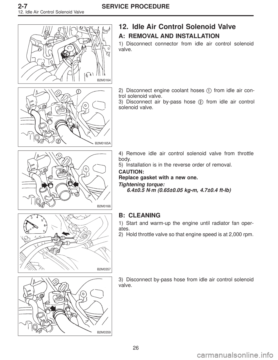
B2M0164
12. Idle Air Control Solenoid Valve
A: REMOVAL AND INSTALLATION
1) Disconnect connector from idle air control solenoid
valve.
B2M0165A
2) Disconnect engine coolant hoses�1from idle air con-
trol solenoid valve.
3) Disconnect air by-pass hose�
2from idle air control
solenoid valve.
B2M0166
4) Remove idle air control solenoid valve from throttle
body.
5) Installation is in the reverse order of removal.
CAUTION:
Replace gasket with a new one.
Tightening torque:
6.4±0.5 N⋅m (0.65±0.05 kg-m, 4.7±0.4 ft-lb)
B2M0357
B: CLEANING
1) Start and warm-up the engine until radiator fan oper-
ates.
2) Hold throttle valve so that engine speed is at 2,000 rpm.
B2M0359
3) Disconnect by-pass hose from idle air control solenoid
valve.
26
2-7SERVICE PROCEDURE
12. Idle Air Control Solenoid Valve
Page 546 of 2890
B2M0362
3) Remove pressure sources switching solenoid valve
from bracket.
4) Installation is in the reverse order of removal.
Tightening torque:
6.4±0.5 N⋅m (0.65±0.05 kg-m, 4.7±0.4 ft-lb)
G2M0398
14. Fuel Injector
A: REMOVAL AND INSTALLATION
1) Release fuel pressure.
2) Disconnect connector from fuel injector.
G2M0431
3) Remove fuel injector from fuel pipe assembly.
B2M0169A
4) Installation is in the reverse order of removal.
CAUTION:
Replace O-rings and insulator.
Tightening torque:
T: 3.4±0.5 N⋅m (0.35±0.05 kg-m, 2.5±0.4 ft-lb)
�
1O-ring B
�
2O-ring A
�
3Fuel injector
�
4Insulator
�
5Fuel injector cup
G6M0095
15. Engine Control Module
A: REMOVAL AND INSTALLATION
1) Disconnect battery ground cable.
28
2-7SERVICE PROCEDURE
13. Pressure Sources Switching Solenoid Valve (AT model) - 15. Engine Control Module
Page 552 of 2890
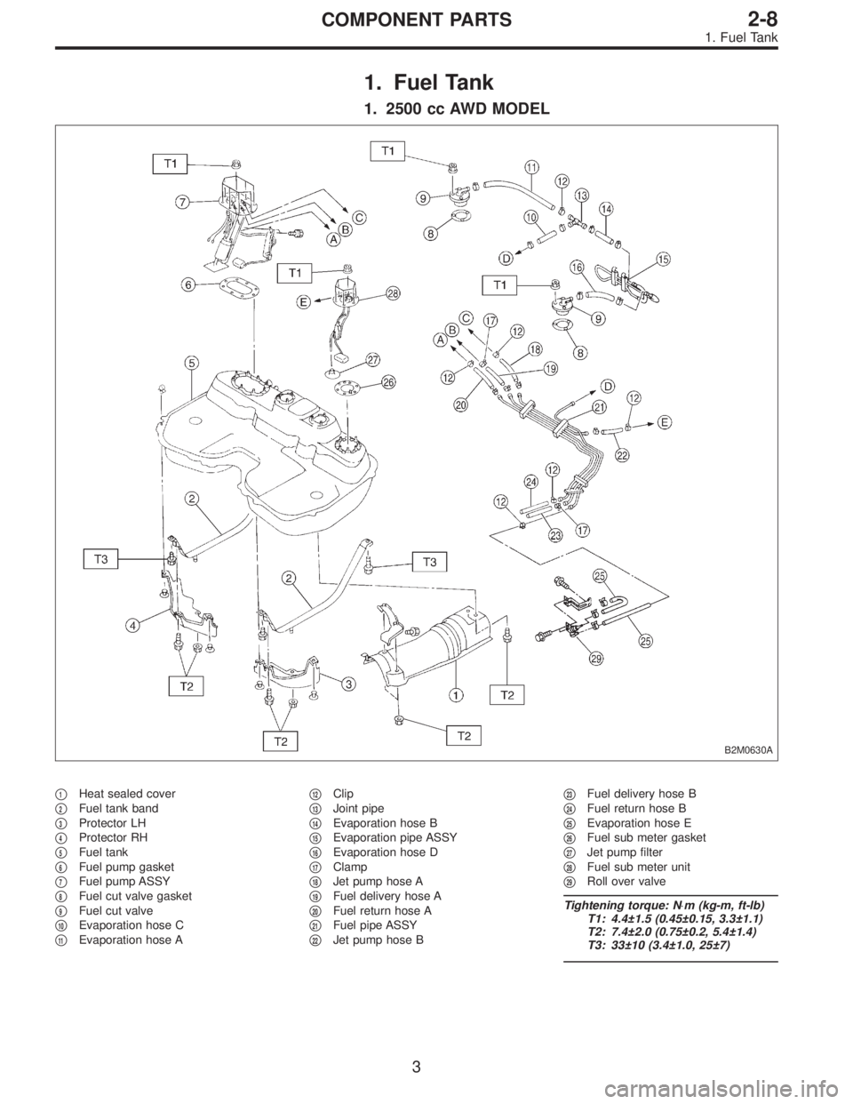
1. Fuel Tank
1. 2500 cc AWD MODEL
B2M0630A
�1Heat sealed cover
�
2Fuel tank band
�
3Protector LH
�
4Protector RH
�
5Fuel tank
�
6Fuel pump gasket
�
7Fuel pump ASSY
�
8Fuel cut valve gasket
�
9Fuel cut valve
�
10Evaporation hose C
�
11Evaporation hose A�
12Clip
�
13Joint pipe
�
14Evaporation hose B
�
15Evaporation pipe ASSY
�
16Evaporation hose D
�
17Clamp
�
18Jet pump hose A
�
19Fuel delivery hose A
�
20Fuel return hose A
�
21Fuel pipe ASSY
�
22Jet pump hose B�
23Fuel delivery hose B
�
24Fuel return hose B
�
25Evaporation hose E
�
26Fuel sub meter gasket
�
27Jet pump filter
�
28Fuel sub meter unit
�
29Roll over valve
Tightening torque: N⋅m (kg-m, ft-lb)
T1: 4.4±1.5 (0.45±0.15, 3.3±1.1)
T2: 7.4±2.0 (0.75±0.2, 5.4±1.4)
T3: 33±10 (3.4±1.0, 25±7)
3
2-8COMPONENT PARTS
1. Fuel Tank
Page 553 of 2890
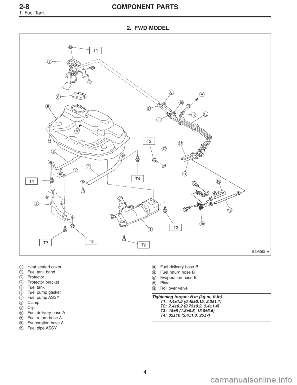
2. FWD MODEL
B2M0631A
�1Heat seated cover
�
2Fuel tank band
�
3Protector
�
4Protector bracket
�
5Fuel tank
�
6Fuel pump gasket
�
7Fuel pump ASSY
�
8Clamp
�
9Clip
�
10Fuel delivery hose A
�
11Fuel return hose A
�
12Evaporation hose A
�
13Fuel pipe ASSY�
14Fuel delivery hose B
�
15Fuel return hose B
�
16Evaporation hose B
�
17Plate
�
18Roll over valve
Tightening torque: N⋅m (kg-m, ft-lb)
T1: 4.4±1.5 (0.45±0.15, 3.3±1.1)
T2: 7.4±0.2 (0.75±0.2, 5.4±1.4)
T3: 18±5 (1.8±0.5, 13.0±3.6)
T4: 33±10 (3.4±1.0, 25±7)
4
2-8COMPONENT PARTS
1. Fuel Tank
 Install rear oxygen sensor.
Tightening torque:
21±3 N⋅m (2.1±0.3 kg-m, 15.2±2.2 ft-lb)
3) Lower the vehicle.
4) Connect connector to rear oxygen sensor.
23
2-7SERVICE PROCEDURE
8. Rear")
 Disconnect connector from camshaft position sensor.
G2M0417
2) Remove camshaft position sensor from camshaft sup-
port LH.
3) Instal")
 Remove pressure sources switching solenoid valve
from bracket.
4) Installation is in the reverse order of removal.
Tightening torque:
6.4±0.5 N⋅m (0.65±0.05 kg-m, 4.7±0.4 ft-lb)
G2M039")