Page 1174 of 2890
G4M0098
8. Pipe Assembly (Power Steering
System) [RHD model]
A: REMOVAL
1) Disconnect battery negative terminal.
B4M0671A
2) Lift vehicle and remove jack-up plate.
3) Remove one pipe joint at the center of gearbox, and
connect vinyl hose to pipe and joint. Discharge fluid by
turning steering wheel fully clockwise and counterclock-
wise. Discharge fluid similarly from the other pipe.
CAUTION:
Improper removal and installation of parts often
causes fluid leak trouble. To prevent this, clean the
surrounding portions before disassembly and
reassembly, and pay special attention to keep dirt and
other foreign matter from mating surfaces.
B4M0672A
4) Remove clamp E from pipes C and D.
67
4-3SERVICE PROCEDURE
8. Pipe Assembly (Power Steering System) [RHD model]
Page 1175 of 2890
 Remove flare nuts from control valve of gearbox
assembly, and then disconnect pipe C⋅D.
CAUTION:
�When disconnecting pipe C⋅D, use two wrenches to
prevent deformities.
�Be careful to keep pipe")
5) Remove flare nuts from control valve of gearbox
assembly, and then disconnect pipe C⋅D.
CAUTION:
�When disconnecting pipe C⋅D, use two wrenches to
prevent deformities.
�Be careful to keep pipe connections free from for-
eign matter.
B4M0556A
6) Remove bolt A.
Disconnect pipe C from oil pump. Disconnect pipe D from
oil tank.
CAUTION:
�Do not allow fluid from the hose end to come into
contact with pulley belt.
�To prevent foreign matter from entering the hose
and pipe, cover the open ends of them with a clean
cloth.
B: CHECK
Check all disassembled parts for wear, damage or other
abnormalities. Repair or replace faulty parts as required.
Part name Inspection Remedy
Pipe�O-ring fitting surface for
damage
�Nut for damage
�Pipe for damageReplace with new one.
Clamp
�Clamps for weak
clamping forceReplace with new one.
Clamp E
Hose�Flared surface for
damage
�Flare nut for damage
�Outer surface for cracks
�Outer surface for wear
�Clip for damage
�End coupling or adapter
for degradationReplace with new one.
68
4-3SERVICE PROCEDURE
8. Pipe Assembly (Power Steering System) [RHD model]
Page 1176 of 2890
B4M0556A
C: ASSEMBLY
1) Interconnect pipes C and D.
Tightening torque:
Joint nut
15±5 N⋅m (1.5±0.5 kg-m, 10.8±3.6 ft-lb)
CAUTION:
Visually check that hose between tank and pipe D is
free from bending or twisting.
2) Tighten bolt A.
Tightening torque:
13±3 N⋅m (1.3±0.3 kg-m, 9.4±2.2 ft-lb)
B4M0673A
3) Temporarily connect pipes C and D to control valve of
gearbox.
B4M0667A
4) Temporarily install clamp E on pipes C and D.
CAUTION:
Ensure that the letter“8”side of clamp E is on the pipe
C side as shown in the figure.
5) Tighten clamp E firmly.
Tightening torque:
7.4±2.0 N⋅m (0.75±0.20 kg-m, 5.4±1.4 ft-lb)
6) Tighten joint nut.
Tightening torque:
15±5 N⋅m (1.5±0.5 kg-m, 10.8±3.6 ft-lb)
69
4-3SERVICE PROCEDURE
8. Pipe Assembly (Power Steering System) [RHD model]
Page 1177 of 2890
B4M0671A
7) Connect pipes A and B to four pipe joints of gearbox.
Connect upper pipe A first, and lower pipe B second.
Tightening torque:
13±3 N⋅m (1.3±0.3 kg-m, 9.4±2.2 ft-lb)
8) Install jack-up plate.
9) Connect battery negative terminal.
10) Feed the specified fluid and discharge air.
NOTE:
Never start the engine before feeding the fluid; otherwise
vane pump might be seized up.
B4M0674A
70
4-3SERVICE PROCEDURE
8. Pipe Assembly (Power Steering System) [RHD model]
Page 1194 of 2890
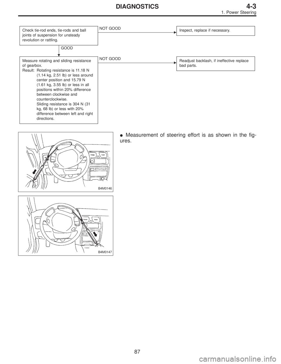
Check tie-rod ends, tie-rods and ball
joints of suspension for unsteady
revolution or rattling.
GOOD
�NOT GOOD
Inspect, replace if necessary.
Measure rotating and sliding resistance
of gearbox.
Result: Rotating resistance is 11.18 N
(1.14 kg, 2.51 lb) or less around
center position and 15.79 N
(1.61 kg, 3.55 lb) or less in all
positions within 20% difference
between clockwise and
counterclockwise.
Sliding resistance is 304 N (31
kg, 68 lb) or less with 20%
difference between left and right
directions.�NOT GOOD
Readjust backlash, if ineffective replace
bad parts.
B4M0146
�Measurement of steering effort is as shown in the fig-
ures.
B4M0147
�
87
4-3DIAGNOSTICS
1. Power Steering
Page 1195 of 2890
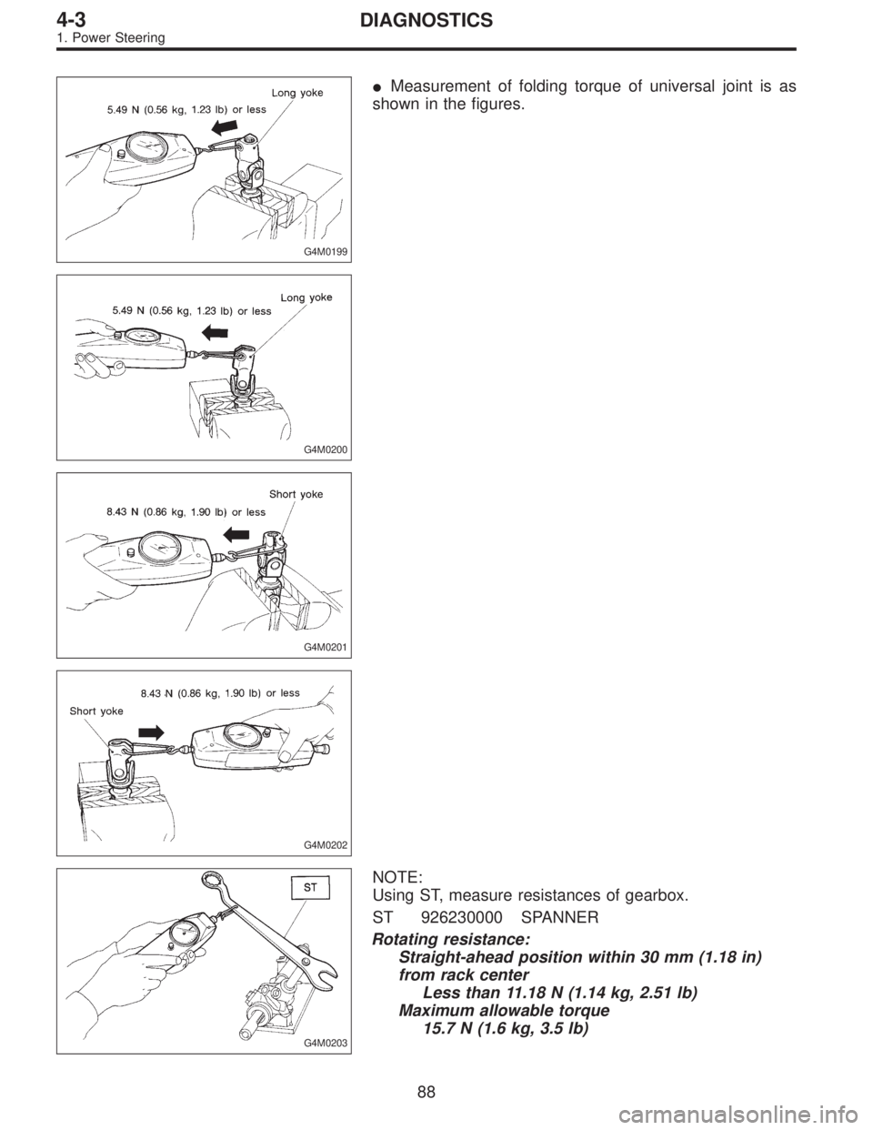
G4M0199
�Measurement of folding torque of universal joint is as
shown in the figures.
G4M0200
G4M0201
G4M0202
G4M0203
NOTE:
Using ST, measure resistances of gearbox.
ST 926230000 SPANNER
Rotating resistance:
Straight-ahead position within 30 mm (1.18 in)
from rack center
Less than 11.18 N (1.14 kg, 2.51 lb)
Maximum allowable torque
15.7 N (1.6 kg, 3.5 lb)
88
4-3DIAGNOSTICS
1. Power Steering
Page 1197 of 2890

CAUTION:
It is likely that although one judges fluid leakage, there
is actually no leakage. This is because the fluid spilt
during the last maintenance was not completely")
4. FLUID LEAKAGE (LHD MODEL)
CAUTION:
It is likely that although one judges fluid leakage, there
is actually no leakage. This is because the fluid spilt
during the last maintenance was not completely wiped
off. Be sure to wipe off spilt fluid thoroughly after
maintenance.
Leakage from connecting portions of
pipes and hoses, numbered with�1thru�9in figure
�Insufficient tightening of flare nut,
catching dirt or the like, damage to
flare or flare nut�Loosen and retighten, if ineffective,
replace.
�Poor insertion of hose, poor clamp-
ing�Retighten or replace clamp.
�Damaged O-ring�Replace O-ring pipe or hose with
new one, if ineffective, replace gear-
box also.
Leakage from hose�10and�11in
figure�Crack or damage in hose�Replace with a new one.
�Crack or damage in hose hardware�
Leakage from surrounding of cast
iron portion of oil pump�12and�13in
figure�Damaged oil seal�Replace oil seal.
�Damaged oil seal�
Leakage from oil tank,�14and�15in figure�Crack in oil tank,�14�Replace oil tank.
�Damaged O-ring,�15�Replace O-ring.
Leakage from filler neck�16�Damaged cap packing�Replace cap.
�Crack in root of filler neck�Replace oil tank.
�High fluid level *5�Adjust fluid level.
Leakage from surrounding of power
cylinder of gearbox,�17in figure�Damaged oil seal�Replace bad parts.
Leakage from control valve of
gearbox,�18and�19in figure�Damaged packing or oil seal�
�Damage in control valve�
*5 Fluid level is specified at optimum position (range) for ordinary use. Accordingly, if the vehicle is used often under hard con-
ditions such as on very rough roads or in mountainous areas, fluid may bleed out from cap air vent hole. This is not a prob-
lem. If a customer complains strongly and is not likely to be satisfied with the leakage, lower the fluid level to the extent that
fluid will not bleed out under the conditions described, and have the customer check the fluid level and its quality more fre-
quency than usual.
90
4-3DIAGNOSTICS
1. Power Steering
Page 1199 of 2890

CAUTION:
It is likely that although one judges fluid leakage, there
is actually no leakage. This is because the fluid spilt
during the last maintenance was not completely")
5. FLUID LEAKAGE (RHD MODEL)
CAUTION:
It is likely that although one judges fluid leakage, there
is actually no leakage. This is because the fluid spilt
during the last maintenance was not completely wiped
off. Be sure to wipe off spilt fluid thoroughly after
maintenance.
Leakage from connecting portions of
pipes and hoses, numbered with�1thru�9in figure
�Insufficient tightening of flare nut,
catching dirt or the like, damage to
flare or flare nut�Loosen and retighten, if ineffective,
replace.
�Poor insertion of hose, poor clamp-
ing�Retighten or replace clamp.
�Damaged O-ring�Replace O-ring pipe or hose with
new one, if ineffective, replace gear-
box also.
Leakage from hose�10and�11in
figure�Crack or damage in hose�Replace with a new one.
�Crack or damage in hose hardware�
Leakage from surrounding of cast
iron portion of oil pump�12and�13in
figure�Damaged oil seal�Replace oil seal.
�Damaged oil seal�
Leakage from oil tank,�14and�15in figure�Crack in oil tank,�14�Replace oil tank.
�Damaged O-ring,�15�Replace O-ring.
Leakage from filler neck�16�Damaged cap packing�Replace cap.
�Crack in root of filler neck�Replace oil tank.
�High fluid level *5�Adjust fluid level.
Leakage from surrounding of power
cylinder of gearbox,�17in figure�Damaged oil seal�Replace bad parts.
Leakage from control valve of
gearbox,�18and�19in figure�Damaged packing or oil seal�
�Damage in control valve�
*5 Fluid level is specified at optimum position (range) for ordinary use. Accordingly, if the vehicle is used often under hard con-
ditions such as on very rough roads or in mountainous areas, fluid may bleed out from cap air vent hole. This is not a prob-
lem. If a customer complains strongly and is not likely to be satisfied with the leakage, lower the fluid level to the extent that
fluid will not bleed out under the conditions described, and have the customer check the fluid level and its quality more fre-
quency than usual.
92
4-3DIAGNOSTICS
1. Power Steering
![SUBARU LEGACY 1996 Service Repair Manual G4M0098
8. Pipe Assembly (Power Steering
System) [RHD model]
A: REMOVAL
1) Disconnect battery negative terminal.
B4M0671A
2) Lift vehicle and remove jack-up plate.
3) Remove one pipe joint at the cent](/manual-img/17/57433/w960_57433-1173.png "SUBARU LEGACY 1996 Service Repair Manual G4M0098
8. Pipe Assembly (Power Steering
System) [RHD model]
A: REMOVAL
1) Disconnect battery negative terminal.
B4M0671A
2) Lift vehicle and remove jack-up plate.
3) Remove one pipe joint at the cent")
 Interconnect pipes C and D.
Tightening torque:
Joint nut
15±5 N⋅m (1.5±0.5 kg-m, 10.8±3.6 ft-lb)
CAUTION:
Visually check that hose between tank and pipe D is
free from ben")
 Connect pipes A and B to four pipe joints of gearbox.
Connect upper pipe A first, and lower pipe B second.
Tightening torque:
13±3 N⋅m (1.3±0.3 kg-m, 9.4±2.2 ft-lb)
8) Install jack-up")