Page 1104 of 2890

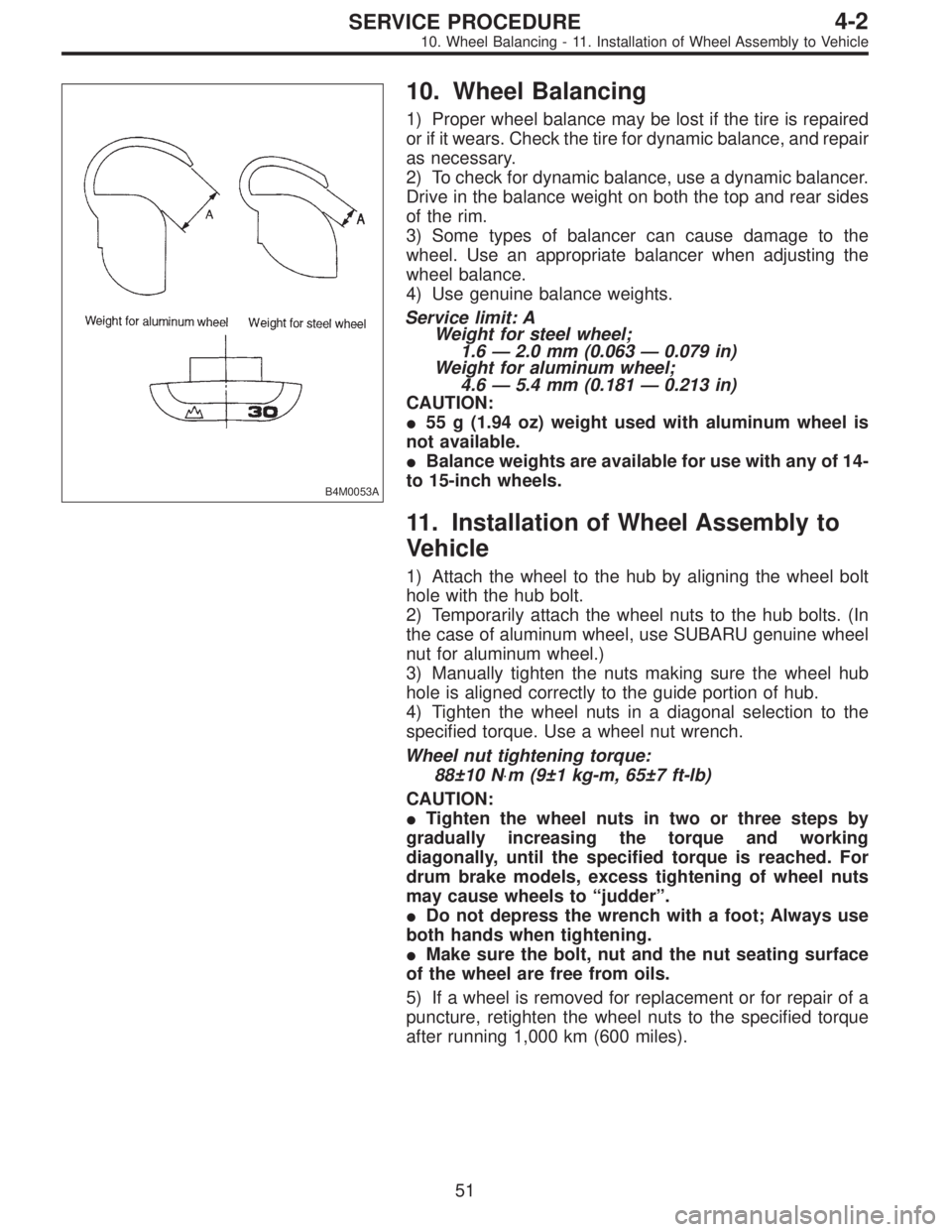
B4M0053A
10. Wheel Balancing
1) Proper wheel balance may be lost if the tire is repaired
or if it wears. Check the tire for dynamic balance, and repair
as necessary.
2) To check for dynamic balance, use a dynamic balancer.
Drive in the balance weight on both the top and rear sides
of the rim.
3) Some types of balancer can cause damage to the
wheel. Use an appropriate balancer when adjusting the
wheel balance.
4) Use genuine balance weights.
Service limit: A
Weight for steel wheel;
1.6—2.0 mm (0.063—0.079 in)
Weight for aluminum wheel;
4.6—5.4 mm (0.181—0.213 in)
CAUTION:
�55 g (1.94 oz) weight used with aluminum wheel is
not available.
�Balance weights are available for use with any of 14-
to 15-inch wheels.
11. Installation of Wheel Assembly to
Vehicle
1) Attach the wheel to the hub by aligning the wheel bolt
hole with the hub bolt.
2) Temporarily attach the wheel nuts to the hub bolts. (In
the case of aluminum wheel, use SUBARU genuine wheel
nut for aluminum wheel.)
3) Manually tighten the nuts making sure the wheel hub
hole is aligned correctly to the guide portion of hub.
4) Tighten the wheel nuts in a diagonal selection to the
specified torque. Use a wheel nut wrench.
Wheel nut tightening torque:
88±10 N⋅m (9±1 kg-m, 65±7 ft-lb)
CAUTION:
�Tighten the wheel nuts in two or three steps by
gradually increasing the torque and working
diagonally, until the specified torque is reached. For
drum brake models, excess tightening of wheel nuts
may cause wheels to “judder”.
�Do not depress the wrench with a foot; Always use
both hands when tightening.
�Make sure the bolt, nut and the nut seating surface
of the wheel are free from oils.
5) If a wheel is removed for replacement or for repair of a
puncture, retighten the wheel nuts to the specified torque
after running 1,000 km (600 miles).
51
4-2SERVICE PROCEDURE
10. Wheel Balancing - 11. Installation of Wheel Assembly to Vehicle
Page 1190 of 2890

1. Power Steering
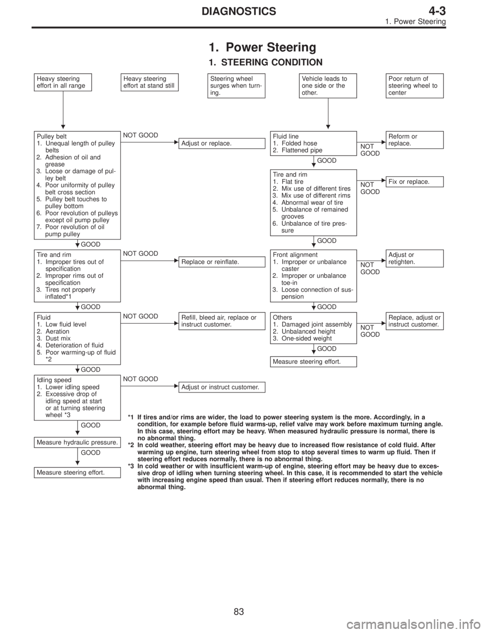
1. STEERING CONDITION
Heavy steering
effort in all rangeHeavy steering
effort at stand stillSteering wheel
surges when turn-
ing.Vehicle leads to
one side or the
other.Poor return of
steering wheel to
center
Pulley belt
1. Unequal length of pulley
belts
2. Adhesion of oil and
grease
3. Loose or damage of pul-
ley belt
4. Poor uniformity of pulley
belt cross section
5. Pulley belt touches to
pulley bottom
6. Poor revolution of pulleys
except oil pump pulley
7. Poor revolution of oil
pump pulley
GOOD
�NOT GOOD
Adjust or replace.Fluid line
1. Folded hose
2. Flattened pipe
GOOD
�NOT
GOODReform or
replace.
Tire and rim
1. Flat tire
2. Mix use of different tires
3. Mix use of different rims
4. Abnormal wear of tire
5. Unbalance of remained
grooves
6. Unbalance of tire pres-
sure
GOOD
�NOT
GOODFix or replace.
Tire and rim
1. Improper tires out of
specification
2. Improper rims out of
specification
3. Tires not properly
inflated*1
GOOD
�NOT GOOD
Replace or reinflate.Front alignment
1. Improper or unbalance
caster
2. Improper or unbalance
toe-in
3. Loose connection of sus-
pension
GOOD
�NOT
GOODAdjust or
retighten.
Fluid
1. Low fluid level
2. Aeration
3. Dust mix
4. Deterioration of fluid
5. Poor warming-up of fluid
*2
GOOD
�NOT GOOD
Refill, bleed air, replace or
instruct customer.Others
1. Damaged joint assembly
2. Unbalanced height
3. One-sided weight
GOOD
Measure steering effort.
�NOT
GOODReplace, adjust or
instruct customer.
Idling speed
1. Lower idling speed
2. Excessive drop of
idling speed at start
or at turning steering
wheel *3
GOOD
�NOT GOOD
Adjust or instruct customer.
*1 If tires and/or rims are wider, the load to power steering system is the more. Accordingly, in a
condition, for example before fluid warms-up, relief valve may work before maximum turning angle.
In this case, steering effort may be heavy. When measured hydraulic pressure is normal, there is
no abnormal thing.
*2 In cold weather, steering effort may be heavy due to increased flow resistance of cold fluid. After
warming up engine, turn steering wheel from stop to stop several times to warm up fluid. Then if
steering effort reduces normally, there is no abnormal thing.
*3 In cold weather or with insufficient warm-up of engine, steering effort may be heavy due to exces-
sive drop of idling when turning steering wheel. In this case, it is recommended to start the vehicle
with increasing engine speed than usual. Then if steering effort reduces normally, there is no
abnormal thing. Measure hydraulic pressure.
GOOD
Measure steering effort.
��
�
��
��
�
�
�
�
83
4-3DIAGNOSTICS
1. Power Steering
Page 1387 of 2890
Tools and Equipment Description
�THERMOMETER
PocketTHERMOMETERSare available from either industrial
hardware store or commercial refrigeration supply houses.
G4M0578
�ELECTRONIC LEAK DETECTOR
AnELECTRONIC LEAK DETECTORcan be obtained from
either a specialty tool supply or an A/C equipment supplier.
G4M0579
�WEIGHT SCALE
AWEIGHT SCALEsuch as an electronic charging scale or a
bathroom scale with digital display will be needed if a 13.6 kg
(30 lb) refrigerant container is used.
G4M0580
14
4-7SERVICE PROCEDURE
3. Tools and Equipment
Page 1393 of 2890

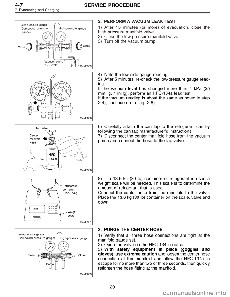
G4M0599
2. PERFORM A VACUUM LEAK TEST
1) After 15 minutes (or more) of evacuation, close the
high-pressure manifold valve.
2) Close the low-pressure manifold valve.
3) Turn off the vacuum pump.
G4M0600
4) Note the low side gauge reading.
5) After 5 minutes, re-check the low-pressure gauge read-
ing.
If the vacuum level has changed more than 4 kPa (25
mmHg, 1 inHg), perform an HFC-134a leak test.
If the vacuum reading is about the same as noted in step
2-4), continue on to step 2-6).
G4M0980
6) Carefully attach the can tap to the refrigerant can by
following the can tap manufacturer’s instructions.
7) Disconnect the center manifold hose from the vacuum
pump and connect the hose to the tap valve.
G4M0981
8) If a 13.6 kg (30 lb) container of refrigerant is used a
weight scale will be needed. This scale is to determine the
amount of refrigerant that is used.
Connect the center hose from the manifold to the valve.
Place the 13.6 kg (30 lb) container on the scale, valve end
down.
G4M0603
3. PURGE THE CENTER HOSE
1) Verify that all three hose connections are tight at the
manifold gauge set.
2) Open the valve on the HFC-134a source.
3)With safety equipment in place (goggles and
gloves), use extreme cautionand loosen the center hose
connection at the manifold and allow the HFC-134a to
escape for no more than two or three seconds, then quickly
retighten the hose fitting at the manifold.
20
4-7SERVICE PROCEDURE
7. Evacuating and Charging
Page 1463 of 2890

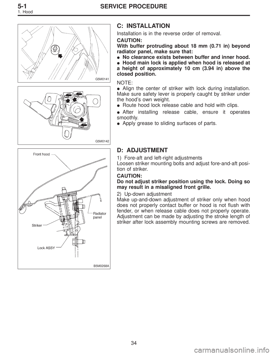
G5M0141
C: INSTALLATION
Installation is in the reverse order of removal.
CAUTION:
With buffer protruding about 18 mm (0.71 in) beyond
radiator panel, make sure that:
�No clearance exists between buffer and inner hood.
�Hood main lock is applied when hood is released at
a height of approximately 10 cm (3.94 in) above the
closed position.
G5M0142
NOTE:
�Align the center of striker with lock during installation.
Make sure safety lever is properly caught by striker under
the hood’s own weight.
�Route hood lock release cable and hold with clips.
�After installing release cable, ensure it operates
smoothly.
�Apply grease to sliding surfaces of parts.
B5M0268A
D: ADJUSTMENT
1) Fore-aft and left-right adjustments
Loosen striker mounting bolts and adjust fore-and-aft posi-
tion of striker.
CAUTION:
Do not adjust striker position using the lock. Doing so
may result in a misaligned front grille.
2) Up-down adjustment
Make up-and-down adjustment of striker only when hood
does not properly contact buffer or hood is not flush with
fender, or when release cable does not properly operate.
Adjustment can be made by adjusting the stroke length of
striker after lock assembly mounting screws are removed.
34
5-1SERVICE PROCEDURE
1. Hood
Page 1464 of 2890
G5M0144
2. Trunk Lid
A: REMOVAL
1. TRUNK LID
1) Open trunk lid.
2) Remove trunk lid mounting bolts and detach trunk lid
from hinges.
G5M0145
2. TORSION BAR
1) Open trunk lid. Remove torsion bars from hinge links
using ST.
ST 927780000 REMOVER
CAUTION:
Be careful because torsion bar quickly swings back
when released.
2) Remove the left and right torsion bars.
WARNING:
Be careful because trunk lid drops under its own
weight when torsion bars are removed.
G5M0146
3. TRUNK LID LOCK ASSEMBLY AND KEY
CYLINDER
1) Remove rod of lock assembly from rod holder of key
lock assembly.
2) Remove nuts which hold lock assembly and remove
lock assembly.
NOTE:
�Always remove rear skirt trim panel beforehand, if so
equipped.
�Be careful not to bend opener cable.
B5M0269A
3) Remove rod holder and detach key cylinder from trunk
lid.
35
5-1SERVICE PROCEDURE
2. Trunk Lid
Page:
< prev 1-8 9-16 17-24