Page 329 of 2890
B: INSPECTION
1. TIMING BELT
1) Check timing belt teeth for breaks, cracks, and wear. If
any fault is found, replace belt.
2) Check the condition of back side of belt; if any crack is
found, replace belt.
CAUTION:
�Be careful not to let oil, grease or coolant contact
the belt. Remove quickly and thoroughly if this hap-
pens.
G2M0115
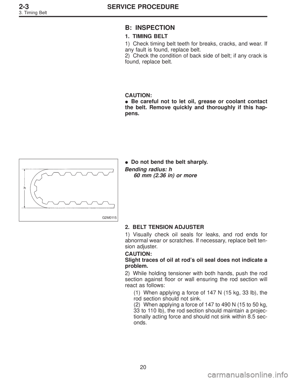
�Do not bend the belt sharply.
Bending radius: h
60 mm (2.36 in) or more
2. BELT TENSION ADJUSTER
1) Visually check oil seals for leaks, and rod ends for
abnormal wear or scratches. If necessary, replace belt ten-
sion adjuster.
CAUTION:
Slight traces of oil at rod’s oil seal does not indicate a
problem.
2) While holding tensioner with both hands, push the rod
section against floor or wall ensuring the rod section will
react as follows:
(1) When applying a force of 147 N (15 kg, 33 lb), the
rod section should not sink.
(2) When applying a force of 147 to 490 N (15 to 50 kg,
33 to 110 lb), the rod section should maintain a projec-
tionally acting force and should not sink within 8.5 sec-
onds.
20
2-3SERVICE PROCEDURE
3. Timing Belt
Page 336 of 2890
4. Valve Rocker Assembly
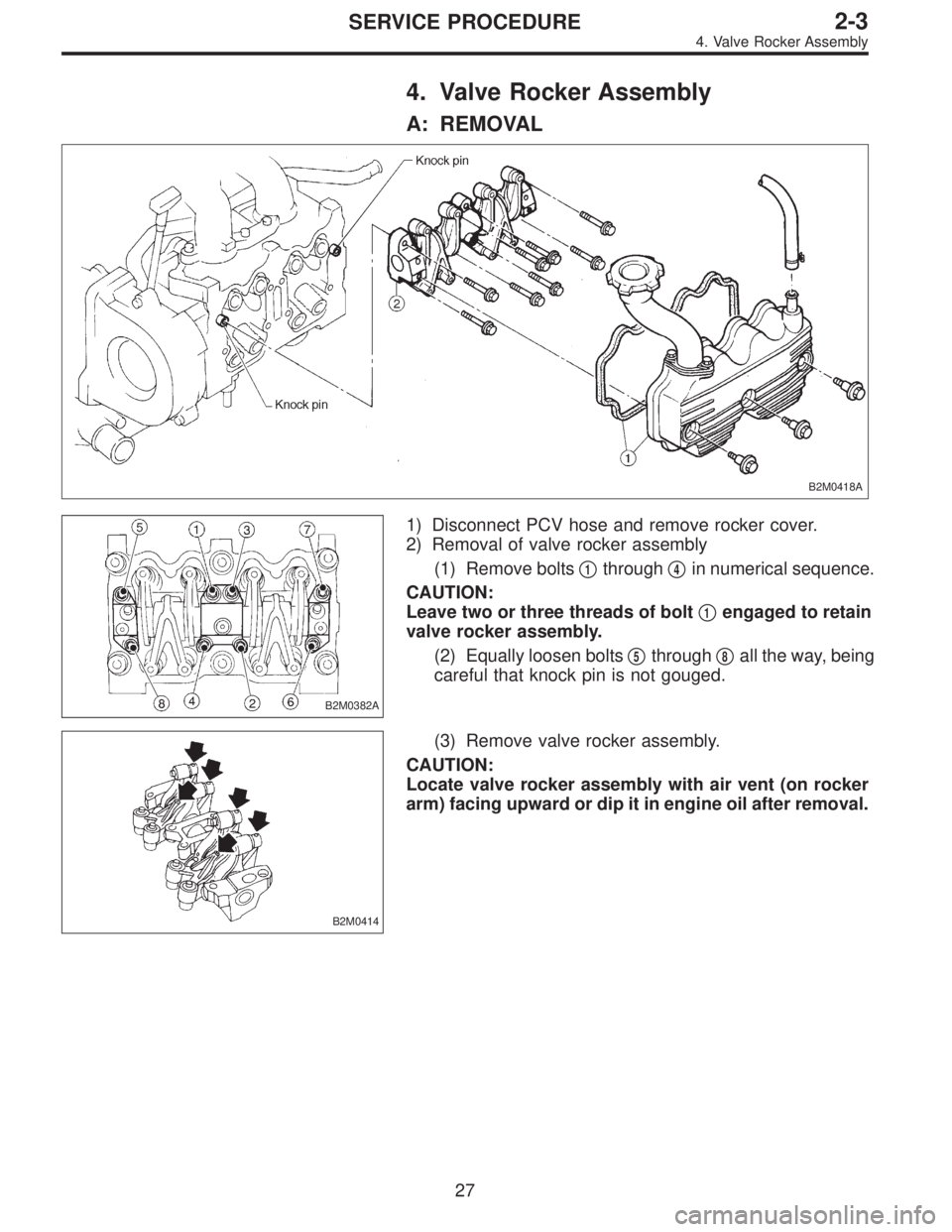
A: REMOVAL
B2M0418A
B2M0382A
1) Disconnect PCV hose and remove rocker cover.
2) Removal of valve rocker assembly
(1) Remove bolts�
1through�4in numerical sequence.
CAUTION:
Leave two or three threads of bolt�
1engaged to retain
valve rocker assembly.
(2) Equally loosen bolts�
5through�8all the way, being
careful that knock pin is not gouged.
B2M0414
(3) Remove valve rocker assembly.
CAUTION:
Locate valve rocker assembly with air vent (on rocker
arm) facing upward or dip it in engine oil after removal.
27
2-3SERVICE PROCEDURE
4. Valve Rocker Assembly
Page 337 of 2890
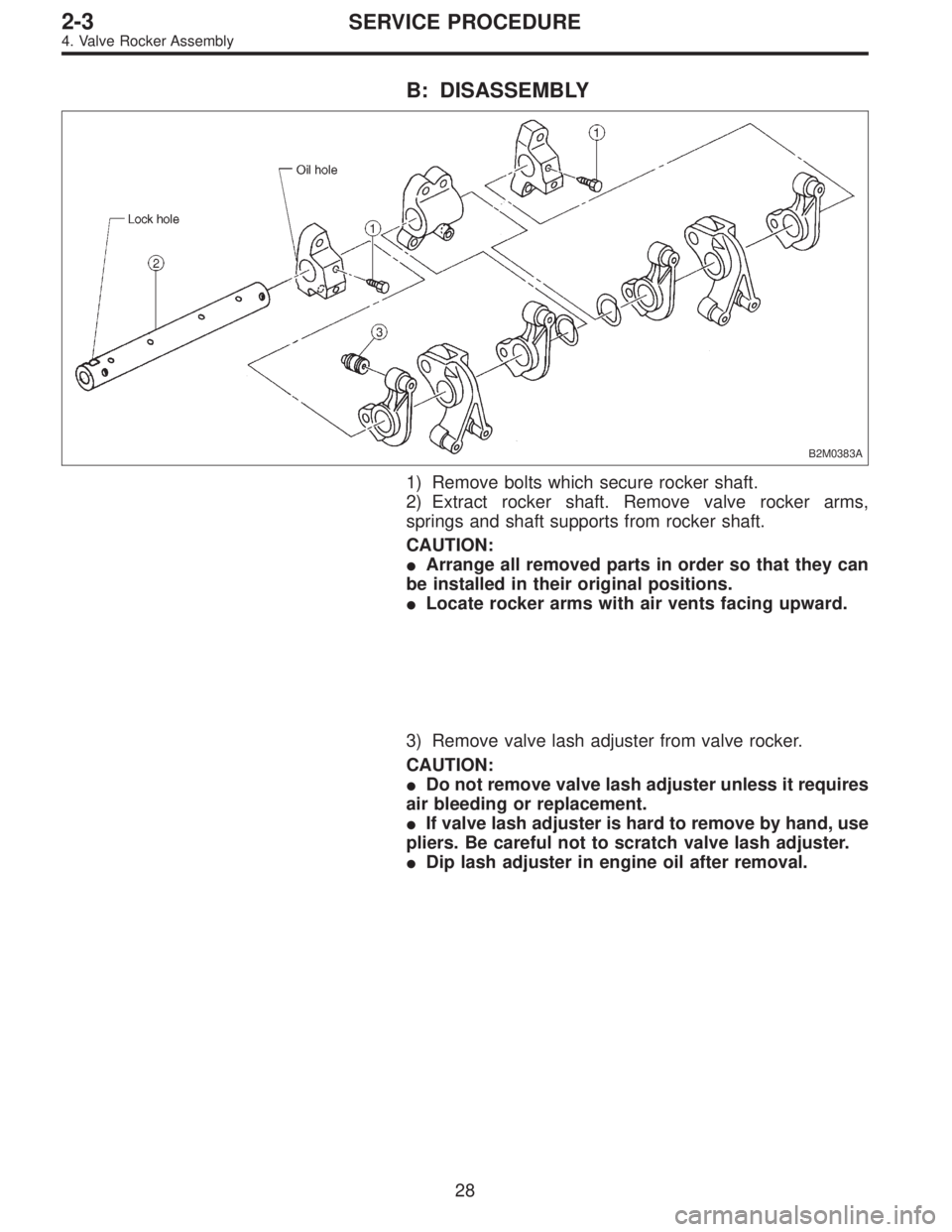
B: DISASSEMBLY
B2M0383A
1) Remove bolts which secure rocker shaft.
2) Extract rocker shaft. Remove valve rocker arms,
springs and shaft supports from rocker shaft.
CAUTION:
�Arrange all removed parts in order so that they can
be installed in their original positions.
�Locate rocker arms with air vents facing upward.
3) Remove valve lash adjuster from valve rocker.
CAUTION:
�Do not remove valve lash adjuster unless it requires
air bleeding or replacement.
�If valve lash adjuster is hard to remove by hand, use
pliers. Be careful not to scratch valve lash adjuster.
�Dip lash adjuster in engine oil after removal.
28
2-3SERVICE PROCEDURE
4. Valve Rocker Assembly
Page 338 of 2890
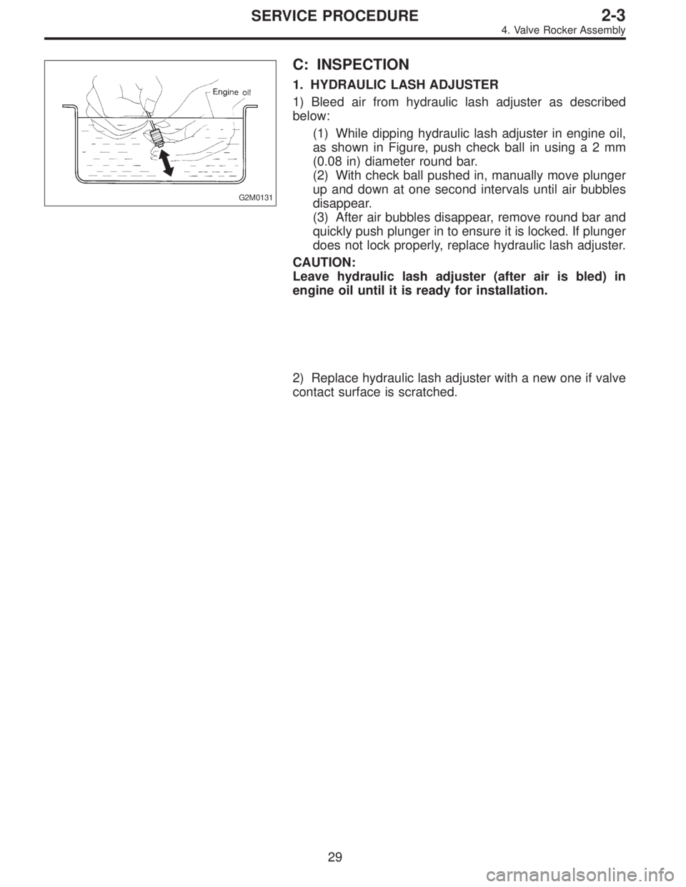
G2M0131
C: INSPECTION
1. HYDRAULIC LASH ADJUSTER
1) Bleed air from hydraulic lash adjuster as described
below:
(1) While dipping hydraulic lash adjuster in engine oil,
as shown in Figure, push check ball in usinga2mm
(0.08 in) diameter round bar.
(2) With check ball pushed in, manually move plunger
up and down at one second intervals until air bubbles
disappear.
(3) After air bubbles disappear, remove round bar and
quickly push plunger in to ensure it is locked. If plunger
does not lock properly, replace hydraulic lash adjuster.
CAUTION:
Leave hydraulic lash adjuster (after air is bled) in
engine oil until it is ready for installation.
2) Replace hydraulic lash adjuster with a new one if valve
contact surface is scratched.
29
2-3SERVICE PROCEDURE
4. Valve Rocker Assembly
Page 339 of 2890
B2M0072
B2M0073
2. VALVE ROCKER ARM
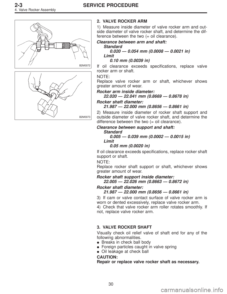
1) Measure inside diameter of valve rocker arm and out-
side diameter of valve rocker shaft, and determine the dif-
ference between the two (= oil clearance).
Clearance between arm and shaft:
Standard
0.020—0.054 mm (0.0008—0.0021 in)
Limit
0.10 mm (0.0039 in)
If oil clearance exceeds specifications, replace valve
rocker arm or shaft.
NOTE:
Replace valve rocker arm or shaft, whichever shows
greater amount of wear.
Rocker arm inside diameter:
22.020—22.041 mm (0.8669—0.8678 in)
Rocker shaft diameter:
21.987—22.000 mm (0.8656—0.8661 in)
2) Measure inside diameter of rocker shaft support and
outside diameter of valve rocker shaft, and determine the
difference between the two (= oil clearance).
Clearance between support and shaft:
Standard
0.005—0.039 mm (0.0002—0.0015 in)
Limit
0.05 mm (0.0020 in)
If oil clearance exceeds specifications, replace rocker shaft
support or shaft.
NOTE:
Replace rocker shaft support or shaft, whichever shows
greater amount of wear.
Rocker shaft support inside diameter:
22.005—22.026 mm (0.8663—0.8672 in)
Rocker shaft diameter:
21.987—22.000 mm (0.8656—0.8661 in)
3) If cam or valve contact surface of valve rocker arm is
worn or dented excessively, replace valve rocker arm.
4) Check that valve rocker arm roller rotates smoothly. If
not, replace valve rocker arm.
3. VALVE ROCKER SHAFT
Visually check oil relief valve of shaft end for any of the
following abnormalities.
�Breaks in check ball body
�Foreign particles caught in valve spring
�Oil leakage at check ball
CAUTION:
Repair or replace valve rocker shaft as necessary.
30
2-3SERVICE PROCEDURE
4. Valve Rocker Assembly
Page 340 of 2890
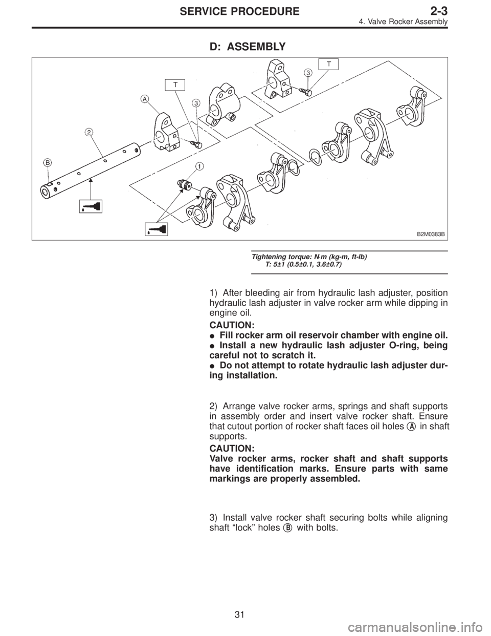
D: ASSEMBLY
B2M0383B
Tightening torque: N⋅m (kg-m, ft-lb)
T: 5±1 (0.5±0.1, 3.6±0.7)
1) After bleeding air from hydraulic lash adjuster, position
hydraulic lash adjuster in valve rocker arm while dipping in
engine oil.
CAUTION:
�Fill rocker arm oil reservoir chamber with engine oil.
�Install a new hydraulic lash adjuster O-ring, being
careful not to scratch it.
�Do not attempt to rotate hydraulic lash adjuster dur-
ing installation.
2) Arrange valve rocker arms, springs and shaft supports
in assembly order and insert valve rocker shaft. Ensure
that cutout portion of rocker shaft faces oil holes�
Ain shaft
supports.
CAUTION:
Valve rocker arms, rocker shaft and shaft supports
have identification marks. Ensure parts with same
markings are properly assembled.
3) Install valve rocker shaft securing bolts while aligning
shaft“lock”holes�
Bwith bolts.
31
2-3SERVICE PROCEDURE
4. Valve Rocker Assembly
Page 342 of 2890
5. Camshaft
A: REMOVAL
1. RELATED PARTS
1) Remove timing belt, camshaft sprockets and related
parts.
2) Remove valve rocker assembly.
2. CAMSHAFT LH
B2M0384A
1) Remove oil level gauge guide attaching bolt.
2) Remove camshaft support LH.
CAUTION:
Do not damage the camshaft position sensor.
3) Remove O-ring.
4) Remove camshaft LH.
5) Remove oil seal.
CAUTION:
�Do not remove oil seal unless necessary.
�Do not scratch journal surface when removing oil
seal.
33
2-3SERVICE PROCEDURE
5. Camshaft
Page 343 of 2890
3. CAMSHAFT RH
B2M0385A
1) Remove camshaft support RH.
2) Remove O-ring.
3) Remove camshaft.
4) Remove oil seal.
CAUTION:
�Do not remove oil seal unless necessary.
�Do not scratch journal surface when removing oil
seal.
G2M0137
B: INSPECTION
1. CAMSHAFT
1) Measure the bend, and repair or replace if necessary.
Limit:
0.025 mm (0.0010 in)
2) Check journal for damage and wear. Replace if faulty.
34
2-3SERVICE PROCEDURE
5. Camshaft