Page 552 of 2890
1. Fuel Tank
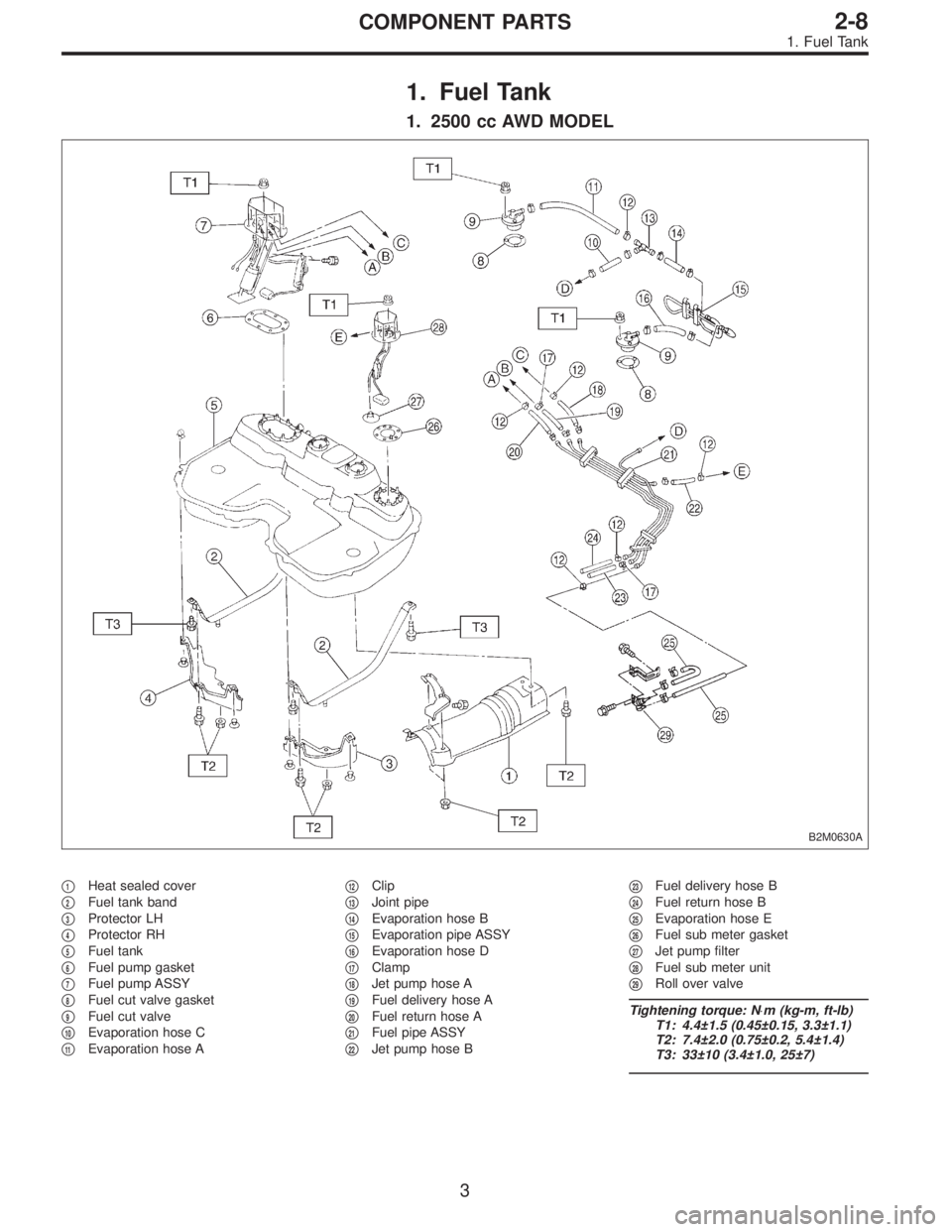
1. 2500 cc AWD MODEL
B2M0630A
�1Heat sealed cover
�
2Fuel tank band
�
3Protector LH
�
4Protector RH
�
5Fuel tank
�
6Fuel pump gasket
�
7Fuel pump ASSY
�
8Fuel cut valve gasket
�
9Fuel cut valve
�
10Evaporation hose C
�
11Evaporation hose A�
12Clip
�
13Joint pipe
�
14Evaporation hose B
�
15Evaporation pipe ASSY
�
16Evaporation hose D
�
17Clamp
�
18Jet pump hose A
�
19Fuel delivery hose A
�
20Fuel return hose A
�
21Fuel pipe ASSY
�
22Jet pump hose B�
23Fuel delivery hose B
�
24Fuel return hose B
�
25Evaporation hose E
�
26Fuel sub meter gasket
�
27Jet pump filter
�
28Fuel sub meter unit
�
29Roll over valve
Tightening torque: N⋅m (kg-m, ft-lb)
T1: 4.4±1.5 (0.45±0.15, 3.3±1.1)
T2: 7.4±2.0 (0.75±0.2, 5.4±1.4)
T3: 33±10 (3.4±1.0, 25±7)
3
2-8COMPONENT PARTS
1. Fuel Tank
Page 555 of 2890
�1Heat sealed cover
�
2Fuel tank band
�
3Protector LH
�
4Protector RH
�
5Fuel tank
�
6Pressure control solenoid valve bracket
�
7Pressure control solenoid valve
�
8Evaporation hose G
�
9Evaporation pipe A
�
10Fuel pump gasket
�
11Fuel pump ASSY
�
12Fuel cut valve gasket
�
13Fuel cut valve
�
14Evaporation hose C
�
15Evaporation hose A
�
16Clip
�
17Joint pipe
�
18Evaporation hose B
�
19Evaporation pipe ASSY�
20Evaporation hose D
�
21Evaporation hose E
�
22Clamp
�
23Jet pump hose A
�
24Fuel delivery hose A
�
25Fuel return hose A
�
26Fuel pipe ASSY
�
27Jet pump hose B
�
28Fuel delivery hose B
�
29Fuel return hose B
�
30Evaporation hose F
�
31Fuel sub meter gasket
�
32Jet pump filter
�
33Fuel sub meter unit
Tightening torque: N⋅m (kg-m, ft-lb)
T1: 4.4±1.5 (0.45±0.15, 3.3±1.1)
T2: 7.4±2.0 (0.75±0.2, 5.4±1.4)
T3: 33±10 (3.4±1.0, 25±7)
6
2-8COMPONENT PARTS
1. Fuel Tank
Page 556 of 2890
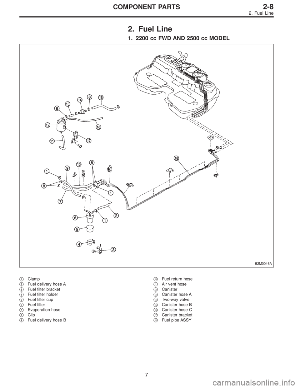
2. Fuel Line
1. 2200 cc FWD AND 2500 cc MODEL
B2M0046A
�1Clamp
�
2Fuel delivery hose A
�
3Fuel filter bracket
�
4Fuel filter holder
�
5Fuel filter cup
�
6Fuel filter
�
7Evaporation hose
�
8Clip
�
9Fuel delivery hose B�
10Fuel return hose
�
11Air vent hose
�
12Canister
�
13Canister hose A
�
14Two-way valve
�
15Canister hose B
�
16Canister hose C
�
17Canister bracket
�
18Fuel pipe ASSY
7
2-8COMPONENT PARTS
2. Fuel Line
Page 558 of 2890

�1Clamp
�
2Fuel delivery hose A
�
3Fuel filter bracket
�
4Fuel filter holder
�
5Fuel filter cup
�
6Fuel filter
�
7Evaporation hose
�
8Clip
�
9Fuel delivery hose B
�
10Fuel return hose
�
11Roll over valve
�
12Roll over valve bracket
�
13Evaporation hose H
�
14Evaporation hose I
�
15Evaporation pipe B
�
16Canister hose A
�
17Canister hose B
�
18Canister holder
�
19Canister upper bracket
�
20Cushion rubber
�
21Canister lower bracket
�
22Canister
�
23Fuel pipe ASSY
�
24Fuel filler valve
�
25Fuel filler pipe
�
26Packing�
27Ring A
�
28Ring B
�
29Fuel filler cap
�
30Fuel filler pipe protector
�
31Fuel tank pressure sensor
�
32Fuel tank pressure sensor hose A
�
33Fuel tank pressure sensor bracket
�
34Grommet
�
35Fuel tank pressure sensor hose B
�
36Air ventilator hose A
�
37Air ventilator pipe A
�
38Air ventilator hose B
�
39Air ventilator pipe B
�
40Air ventilator pipe protector
�
41Vent control solenoid valve
�
42Vent control solenoid valve hose
�
43Air filter hose A
�
44Air filter hose B
�
45Air filter
�
46Tapping screw
Tightening torque: N⋅m (kg-m, ft-lb)
T1: 23±7 (2.3±0.7, 17±5.1)
T2: 25±7 (2.5±0.7, 18±5.1)
9
2-8COMPONENT PARTS
2. Fuel Line
Page 561 of 2890
B2M0049
11) On AWD model, after removing fuel sub meter unit,
drain fuel from there.
WARNING:
Do not use a motor pump when draining fuel.
2. On-Car Services
A: MEASUREMENT OF FUEL PRESSURE
1) Release fuel pressure.
2) Connect connector to fuel pump.
G2M0347
3) Disconnect fuel delivery hoses from fuel filter, and con-
nect fuel pressure gauge.
G2M0348
4) Start the engine.
5) Measure fuel pressure while disconnecting pressure
regulator vacuum hose from collector chamber.
Fuel pressure:
235 — 265 kPa (2.4 — 2.7 kg/cm
2, 34 — 38 psi)
6) After connecting pressure regulator vacuum hose, mea-
sure fuel pressure.
Fuel pressure:
177 — 206 kPa (1.8 — 2.1 kg/cm
2, 26 — 30 psi)
WARNING:
Before removing fuel pressure gauge, release fuel
pressure.
NOTE:
If out of specification as measured at step 6), check or
replace pressure regulator and pressure regulator vacuum
hose.
12
2-8SERVICE PROCEDURE
1. Precautions - 2. On-Car Services
Page 567 of 2890
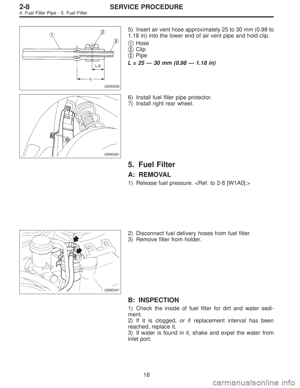
G2M0358
5) Insert air vent hose approximately 25 to 30 mm (0.98 to
1.18 in) into the lower end of air vent pipe and hold clip.
�
1Hose
�
2Clip
�
3Pipe
L=25—30 mm (0.98—1.18 in)
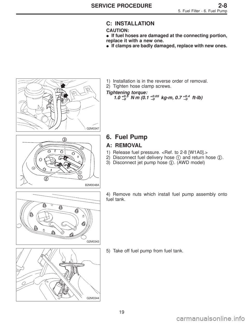
G2M0361
6) Install fuel filler pipe protector.
7) Install right rear wheel.
5. Fuel Filter
A: REMOVAL
1) Release fuel pressure.
G2M0347
2) Disconnect fuel delivery hoses from fuel filter.
3) Remove filter from holder.
B: INSPECTION
1) Check the inside of fuel filter for dirt and water sedi-
ment.
2) If it is clogged, or if replacement interval has been
reached, replace it.
3) If water is found in it, shake and expel the water from
inlet port.
18
2-8SERVICE PROCEDURE
4. Fuel Filler Pipe - 5. Fuel Filter
Page 568 of 2890
C: INSTALLATION
CAUTION:
�If fuel hoses are damaged at the connecting portion,
replace it with a new one.
�If clamps are badly damaged, replace with new ones.
G2M0347
1) Installation is in the reverse order of removal.
2) Tighten hose clamp screws.
Tightening torque:
1.0
+0.5
�0N⋅m (0.1+0.05
�0kg-m, 0.7+0.4
�0ft-lb)
B2M0048A
6. Fuel Pump
A: REMOVAL
1) Release fuel pressure.
2) Disconnect fuel delivery hose�
1and return hose�2.
3) Disconnect jet pump hose�
3. (AWD model)
G2M0343
4) Remove nuts which install fuel pump assembly onto
fuel tank.
G2M0344
5) Take off fuel pump from fuel tank.
19
2-8SERVICE PROCEDURE
5. Fuel Filter - 6. Fuel Pump
Page 576 of 2890
 Fuel pump will not operate.
�Defective terminal contact.Inspect connections, especially groun")
1. Fuel System
Trouble and possible cause Corrective action
1. Insufficient fuel supply to the injector
1) Fuel pump will not operate.
�Defective terminal contact.Inspect connections, especially ground, and tighten
securely.
�Trouble in electromagnetic or electronic circuit parts. Replace fuel pump.
2) Lowering of fuel pump function. Replace fuel pump.
3) Clogged dust or water in the fuel filter. Replace fuel filter, clean or replace fuel tank.
4) Clogged or bent fuel pipe or hose. Clean, correct or replace fuel pipe or hose.
5) Air is mixed in the fuel system. Inspect or retighten each connection part.
6) Clogged or bent breather tube or pipe. Clean, correct or replace air breather tube or pipe.
7) Damaged diaphragm of pressure regulator. Replace.
2. Leakage or blow out fuel
1) Loosened joints of the fuel pipe. Retightening.
2) Cracked fuel pipe, hose and fuel tank. Replace.
3) Defective welding part on the fuel tank. Replace.
4) Defective drain packing of the fuel tank. Replace.
5) Clogged or bent air breather tube or air vent tube. Clean, correct or replace air breather tube or air vent tube.
3. Gasoline smell inside of compartment
1)Loose joints at air breather tube, air vent tube and fuel filler
pipe.Retightening.
2) Defective packing air tightness on the fuel saucer. Correct or replace packing.
3) Cracked fuel separator. Replace separator.
4. Defective fuel meter indicator
1) Defective operation of fuel meter unit. Replace.
2) Defective operation of fuel meter. Replace.
5. Noise
1) Large operation noise or vibration of fuel pump. Replace.
NOTE:
When the vehicle is left unattended for an extended period of time, water may accumulate in the fuel
tank.
�To prevent water condensation:
1) Top off the fuel tank or drain the fuel completely.
2) Drain water condensation from the fuel filter.
�Refilling the fuel tank:
Refill the fuel tank while there is still some fuel left in the tank.
�Protecting the fuel system against freezing and water condensation:
1) Cold areas
In snow-covered areas, mountainous areas, skiing areas, etc. where ambient temperatures drop
below 0°C (32°F) throughout the winter season, use an anti-freeze solution in the cooling system.
Refueling will also complement the effect of anti-freeze solution each time the fuel level drops to about
one-half. After the winter season, drain water which may have accumulated in the fuel filter and fuel
tank in the manner same as that described under affected areas as below.
2) Affected areas
When water condensation is notched in the fuel filter, drain water from both the fuel filter and fuel tank
or use a water removing agent (or anti-freeze solution) in the fuel tank.
�Observe the instructions, notes, etc., indicated on the label affixed to the anti-freeze solution (water
removing agent) container before use.
27
2-8DIAGNOSTICS
1. Fuel System
 On AWD model, after removing fuel sub meter unit,
drain fuel from there.
WARNING:
Do not use a motor pump when draining fuel.
2. On-Car Services
A: MEASUREMENT OF FUEL PRESSURE
1) Release")