Page 678 of 2890
G2M0358
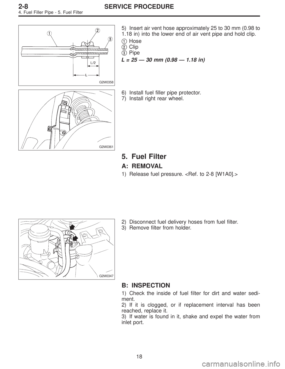
5) Insert air vent hose approximately 25 to 30 mm (0.98 to
1.18 in) into the lower end of air vent pipe and hold clip.
�
1Hose
�
2Clip
�
3Pipe
L=25—30 mm (0.98—1.18 in)
G2M0361
6) Install fuel filler pipe protector.
7) Install right rear wheel.
5. Fuel Filter
A: REMOVAL
1) Release fuel pressure.
G2M0347
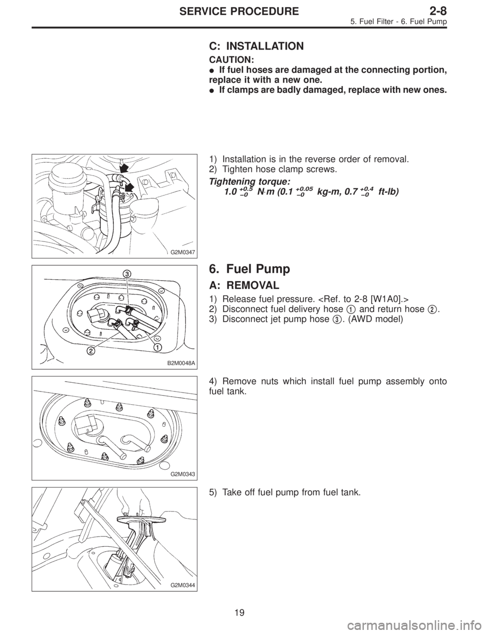
2) Disconnect fuel delivery hoses from fuel filter.
3) Remove filter from holder.
B: INSPECTION
1) Check the inside of fuel filter for dirt and water sedi-
ment.
2) If it is clogged, or if replacement interval has been
reached, replace it.
3) If water is found in it, shake and expel the water from
inlet port.
18
2-8SERVICE PROCEDURE
4. Fuel Filler Pipe - 5. Fuel Filter
Page 679 of 2890
C: INSTALLATION
CAUTION:
�If fuel hoses are damaged at the connecting portion,
replace it with a new one.
�If clamps are badly damaged, replace with new ones.
G2M0347
1) Installation is in the reverse order of removal.
2) Tighten hose clamp screws.
Tightening torque:
1.0
+0.5
�0N⋅m (0.1+0.05
�0kg-m, 0.7+0.4
�0ft-lb)
B2M0048A
6. Fuel Pump
A: REMOVAL
1) Release fuel pressure.
2) Disconnect fuel delivery hose�
1and return hose�2.
3) Disconnect jet pump hose�
3. (AWD model)
G2M0343
4) Remove nuts which install fuel pump assembly onto
fuel tank.
G2M0344
5) Take off fuel pump from fuel tank.
19
2-8SERVICE PROCEDURE
5. Fuel Filter - 6. Fuel Pump
Page 680 of 2890
C: INSTALLATION
CAUTION:
�If fuel hoses are damaged at the connecting portion,
replace it with a new one.
�If clamps are badly damaged, replace with new ones.
G2M0347
1) Installation is in the reverse order of removal.
2) Tighten hose clamp screws.
Tightening torque:
1.0
+0.5
�0N⋅m (0.1+0.05
�0kg-m, 0.7+0.4
�0ft-lb)
B2M0048A
6. Fuel Pump
A: REMOVAL
1) Release fuel pressure.
2) Disconnect fuel delivery hose�
1and return hose�2.
3) Disconnect jet pump hose�
3. (AWD model)
G2M0343
4) Remove nuts which install fuel pump assembly onto
fuel tank.
G2M0344
5) Take off fuel pump from fuel tank.
19
2-8SERVICE PROCEDURE
5. Fuel Filter - 6. Fuel Pump
Page 691 of 2890
 Fuel pump will not operate.
�Defective terminal contact.Inspect connections, especially groun")
1. Fuel System
Trouble and possible cause Corrective action
1. Insufficient fuel supply to the injector
1) Fuel pump will not operate.
�Defective terminal contact.Inspect connections, especially ground, and tighten
securely.
�Trouble in electromagnetic or electronic circuit parts. Replace fuel pump.
2) Lowering of fuel pump function. Replace fuel pump.
3) Clogged dust or water in the fuel filter. Replace fuel filter, clean or replace fuel tank.
4) Clogged or bent fuel pipe or hose. Clean, correct or replace fuel pipe or hose.
5) Air is mixed in the fuel system. Inspect or retighten each connection part.
6) Clogged or bent breather tube or pipe. Clean, correct or replace air breather tube or pipe.
7) Damaged diaphragm of pressure regulator. Replace.
2. Leakage or blow out fuel
1) Loosened joints of the fuel pipe. Retightening.
2) Cracked fuel pipe, hose and fuel tank. Replace.
3) Defective welding part on the fuel tank. Replace.
4) Defective drain packing of the fuel tank. Replace.
5) Clogged or bent air breather tube or air vent tube. Clean, correct or replace air breather tube or air vent tube.
3. Gasoline smell inside of compartment
1)Loose joints at air breather tube, air vent tube and fuel filler
pipe.Retightening.
2) Defective packing air tightness on the fuel saucer. Correct or replace packing.
3) Cracked fuel separator. Replace separator.
4. Defective fuel meter indicator
1) Defective operation of fuel meter unit. Replace.
2) Defective operation of fuel meter. Replace.
5. Noise
1) Large operation noise or vibration of fuel pump. Replace.
NOTE:
When the vehicle is left unattended for an extended period of time, water may accumulate in the fuel
tank.
�To prevent water condensation:
1) Top off the fuel tank or drain the fuel completely.
2) Drain water condensation from the fuel filter.
�Refilling the fuel tank:
Refill the fuel tank while there is still some fuel left in the tank.
�Protecting the fuel system against freezing and water condensation:
1) Cold areas
In snow-covered areas, mountainous areas, skiing areas, etc. where ambient temperatures drop
below 0°C (32°F) throughout the winter season, use an anti-freeze solution in the cooling system.
Refueling will also complement the effect of anti-freeze solution each time the fuel level drops to about
one-half. After the winter season, drain water which may have accumulated in the fuel filter and fuel
tank in the manner same as that described under affected areas as below.
2) Affected areas
When water condensation is notched in the fuel filter, drain water from both the fuel filter and fuel tank
or use a water removing agent (or anti-freeze solution) in the fuel tank.
�Observe the instructions, notes, etc., indicated on the label affixed to the anti-freeze solution (water
removing agent) container before use.
27
2-8DIAGNOSTICS
1. Fuel System
Page 1773 of 2890

�
2Ignition coil
�
3Ignitor
�
4Crankshaft position sensor
�
5Camshaft position sensor
�
6Throttle position sensor
�
7Fuel injectors
�
8Pressure regulator
�
9Engine coolan")
�1Engine control module (ECM)
�
2Ignition coil
�
3Ignitor
�
4Crankshaft position sensor
�
5Camshaft position sensor
�
6Throttle position sensor
�
7Fuel injectors
�
8Pressure regulator
�
9Engine coolant temperature sensor
�
10Mass air flow sensor
�
11Idle air control solenoid valve
�
12Purge control solenoid valve
�
13Fuel pump
�
14PCV valve
�
15Air cleaner
�
16Canister
�
17Main relay
�
18Fuel pump relay
�
19Fuel filter
�
20Front catalytic converter
�
21Rear catalytic converter
�
22EGR valve (AT vehicles only)
�
23EGR control solenoid valve (AT vehicles only)
�
24Radiator fan�
25Radiator fan relay
�
26Pressure sources switching solenoid valve
�
27Knock sensor
�
28Back-pressure transducer (AT vehicles only)
�
29Front oxygen sensor
�
30Rear oxygen sensor (Except 2200 cc California model)
�
31Pressure sensor
�
32A/C compressor
�
33Inhibitor switch
�
34CHECK ENGINE malfunction indicator lamp (MIL)
�
35Tachometer
�
36A/C relay
�
37A/C control module
�
38Ignition switch
�
39Transmission control module (TCM) (AT vehicles only)
�
40ABS/TCS control module (TCS equipped models)
�
41Vehicle speed sensor
�
42Data link connector (For Subaru select monitor)
�
43Data link connector (For Subaru select monitor and OBD-II
general scan tool)
�
44Two way valve
�
45Rear oxygen sensor (2200 cc California model only)
�
46Filter
5
2-7ON-BOARD DIAGNOSTICS II SYSTEM
1. General
Page 1775 of 2890

�
2Ignition coil
�
3Ignitor
�
4Crankshaft position sensor
�
5Camshaft position sensor
�
6Throttle position sensor
�
7Fuel injectors
�
8Pressure regulator
�
9Engine coolan")
�1Engine control module (ECM)
�
2Ignition coil
�
3Ignitor
�
4Crankshaft position sensor
�
5Camshaft position sensor
�
6Throttle position sensor
�
7Fuel injectors
�
8Pressure regulator
�
9Engine coolant temperature sensor
�
10Mass air flow sensor
�
11Idle air control solenoid valve
�
12Purge control solenoid valve
�
13Fuel pump
�
14PCV valve
�
15Air cleaner
�
16Canister
�
17Main relay
�
18Fuel pump relay
�
19Fuel filter
�
20Front catalytic converter
�
21Rear catalytic converter
�
22EGR valve (AT vehicles only)
�
23EGR control solenoid valve (AT vehicles only)
�
24Radiator fan
�
25Radiator fan relay
�
26Pressure sources switching solenoid valve�
27Front oxygen sensor
�
28Rear oxygen sensor (Except 2200 cc California model)
�
29Pressure sensor
�
30A/C compressor (With A/C models)
�
31Inhibitor switch
�
32CHECK ENGINE malfunction indicator lamp (MIL)
�
33Tachometer
�
34A/C relay (With A/C models)
�
35A/C control module (With A/C models)
�
36Ignition switch
�
37Transmission control module (TCM)
�
38Vehicle speed sensor
�
39Data link connector (For Subaru select monitor)
�
40Data link connector (For Subaru select monitor and OBD-II
general scan tool)
�
41Rear oxygen sensor (2200 cc California model)
�
42Knock sensor
�
43Back-pressure transducer (AT vehicles only)
�
44Filter
�
45Fuel tank pressure sensor
�
46Pressure control solenoid valve
�
47Fuel temperature sensor
�
48Fuel level sensor
�
49Vent control solenoid valve
�
50Air filter
7
2-7ON-BOARD DIAGNOSTICS II SYSTEM
1. General
Page 1777 of 2890

�
2Ignition coil
�
3Ignitor
�
4Crankshaft position sensor
�
5Camshaft position sensor
�
6Throttle position sensor
�
7Fuel injectors
�
8Pressure regulator
�
9Engine coolan")
�1Engine control module (ECM)
�
2Ignition coil
�
3Ignitor
�
4Crankshaft position sensor
�
5Camshaft position sensor
�
6Throttle position sensor
�
7Fuel injectors
�
8Pressure regulator
�
9Engine coolant temperature sensor
�
10Mass air flow sensor
�
11Idle air control solenoid valve
�
12Purge control solenoid valve
�
13Fuel pump
�
14PCV valve
�
15Air cleaner
�
16Canister
�
17Main relay
�
18Fuel pump relay
�
19Fuel filter
�
20Front catalytic converter
�
21Rear catalytic converter
�
22EGR valve�
23EGR control solenoid valve
�
24Radiator fan
�
25Radiator fan relay
�
26Pressure sources switching solenoid valve
�
27Knock sensor
�
28Back-pressure transducer
�
29Front oxygen sensor
�
30Rear oxygen sensor
�
31Pressure sensor
�
32A/C compressor
�
33Inhibitor switch
�
34CHECK ENGINE malfunction indicator lamp (MIL)
�
35Tachometer
�
36A/C relay
�
37A/C control module
�
38Ignition switch
�
39Transmission control module (TCM)
�
40Vehicle speed sensor
�
41Data link connector (Subaru select monitor)
�
42Data link connector (OBD-II general scan tool)
�
43Two way valve
�
44Filter
9
2-7ON-BOARD DIAGNOSTICS II SYSTEM
1. General
Page 1779 of 2890

�
2Ignition coil
�
3Ignitor
�
4Crankshaft position sensor
�
5Camshaft position sensor
�
6Throttle position sensor
�
7Fuel injectors
�
8Pressure regulator
�
9Engine coolan")
�1Engine control module (ECM)
�
2Ignition coil
�
3Ignitor
�
4Crankshaft position sensor
�
5Camshaft position sensor
�
6Throttle position sensor
�
7Fuel injectors
�
8Pressure regulator
�
9Engine coolant temperature sensor
�
10Mass air flow sensor
�
11Idle air control solenoid valve
�
12Purge control solenoid valve
�
13Fuel pump
�
14PCV valve
�
15Air cleaner
�
16Canister
�
17Main relay
�
18Fuel pump relay
�
19Fuel filter
�
20Front catalytic converter
�
21Rear catalytic converter
�
22EGR valve
�
23EGR control solenoid valve�
24Radiator fan
�
25Radiator fan relay
�
26Pressure sources switching solenoid valve
�
27Knock sensor
�
28Back-pressure transducer
�
29Front oxygen sensor
�
30Rear oxygen sensor (Except California model)
�
31Pressure sensor
�
32A/C compressor
�
33Inhibitor switch
�
34CHECK ENGINE malfunction indicator lamp (MIL)
�
35Tachometer
�
36A/C relay
�
37A/C control module
�
38Ignition switch
�
39Transmission control module (TCM)
�
40Vehicle speed sensor 2
�
41Data link connector (For Subaru select monitor)
�
42Data link connector (For Subaru select monitor and OBD-II
general scan tool)
�
43Two way valve
�
44Rear oxygen sensor (California model only)
�
45Filter
11
2-7ON-BOARD DIAGNOSTICS II SYSTEM
1. General