B4M0760A
B: REMOVAL
1) Disconnect ground cable from battery.
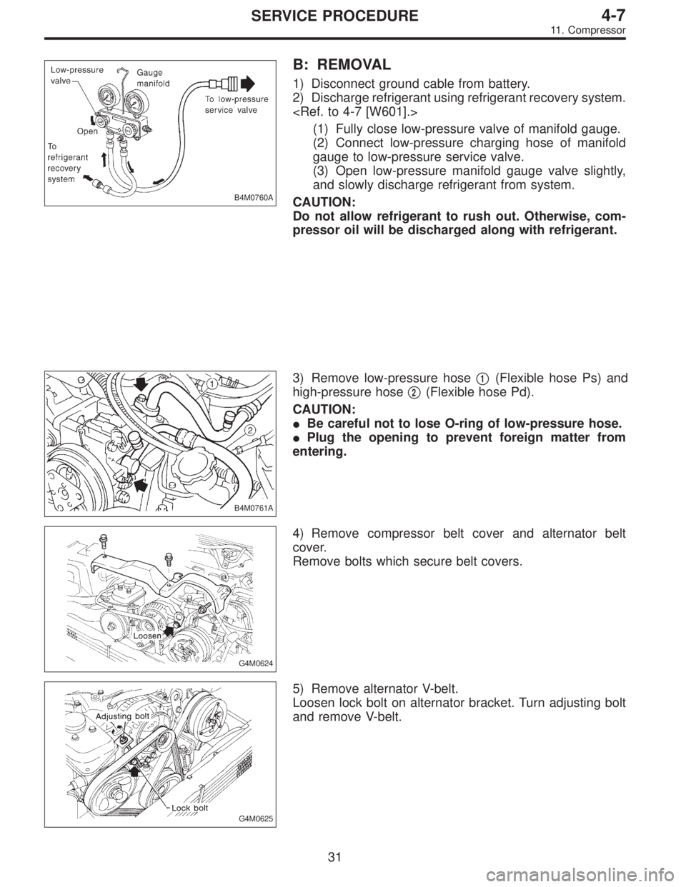
2) Discharge refrigerant using refrigerant recovery system.
(1) Fully close low-pressure valve of manifold gauge.
(2) Connect low-pressure charging hose of manifold
gauge to low-pressure service valve.
(3) Open low-pressure manifold gauge valve slightly,
and slowly discharge refrigerant from system.
CAUTION:
Do not allow refrigerant to rush out. Otherwise, com-
pressor oil will be discharged along with refrigerant.
B4M0761A
3) Remove low-pressure hose�1(Flexible hose Ps) and
high-pressure hose�
2(Flexible hose Pd).
CAUTION:
�Be careful not to lose O-ring of low-pressure hose.
�Plug the opening to prevent foreign matter from
entering.
G4M0624
4) Remove compressor belt cover and alternator belt
cover.
Remove bolts which secure belt covers.
G4M0625
5) Remove alternator V-belt.
Loosen lock bolt on alternator bracket. Turn adjusting bolt
and remove V-belt.
31
4-7SERVICE PROCEDURE
11. Compressor
B6M0358
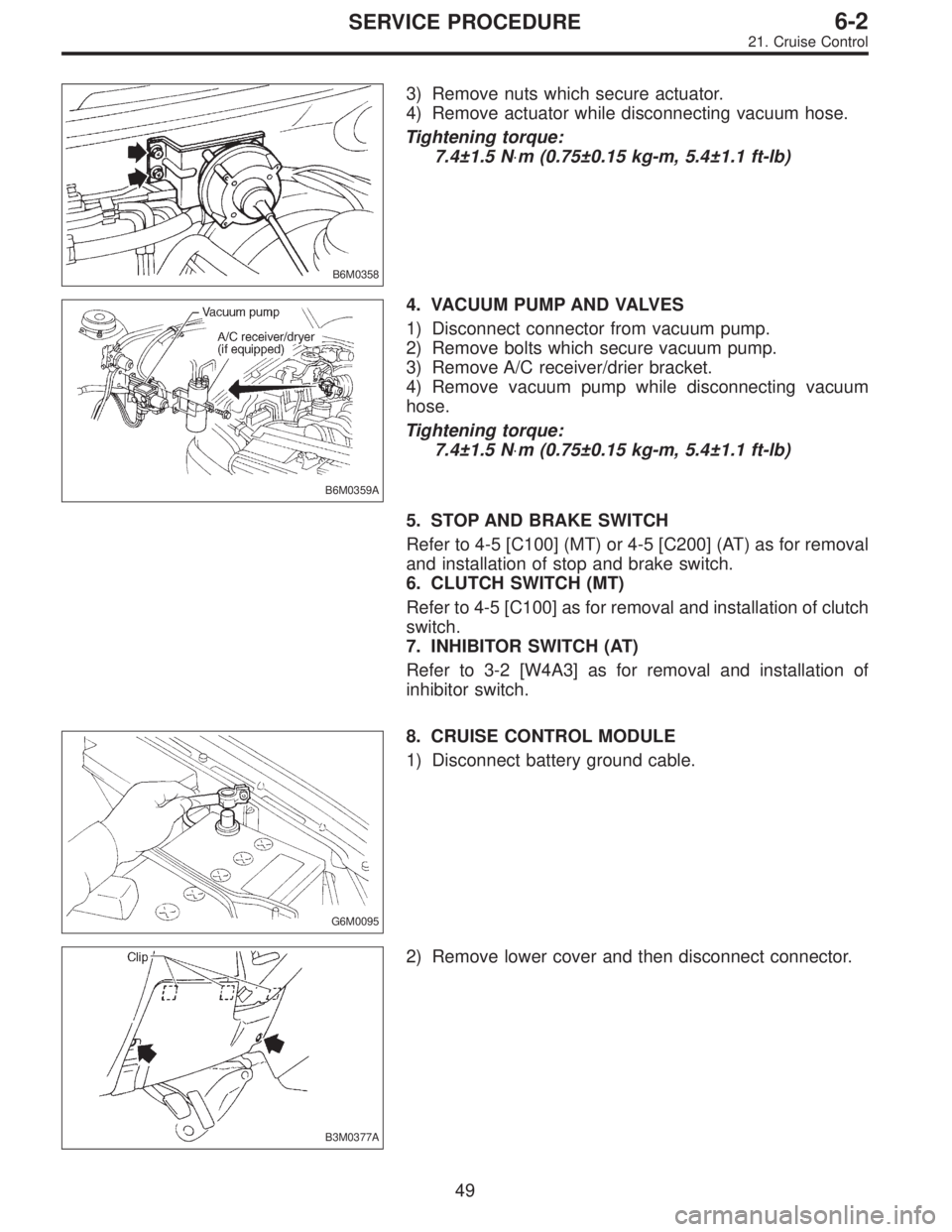
3) Remove nuts which secure actuator.
4) Remove actuator while disconnecting vacuum hose.
Tightening torque:
7.4±1.5 N⋅m (0.75±0.15 kg-m, 5.4±1.1 ft-lb)
B6M0359A
4. VACUUM PUMP AND VALVES
1) Disconnect connector from vacuum pump.
2) Remove bolts which secure vacuum pump.
3) Remove A/C receiver/drier bracket.
4) Remove vacuum pump while disconnecting vacuum
hose.
Tightening torque:
7.4±1.5 N⋅m (0.75±0.15 kg-m, 5.4±1.1 ft-lb)
5. STOP AND BRAKE SWITCH
Refer to 4-5 [C100] (MT) or 4-5 [C200] (AT) as for removal
and installation of stop and brake switch.
6. CLUTCH SWITCH (MT)
Refer to 4-5 [C100] as for removal and installation of clutch
switch.
7. INHIBITOR SWITCH (AT)
Refer to 3-2 [W4A3] as for removal and installation of
inhibitor switch.
G6M0095
8. CRUISE CONTROL MODULE
1) Disconnect battery ground cable.
B3M0377A
2) Remove lower cover and then disconnect connector.
49
6-2SERVICE PROCEDURE
21. Cruise Control