Page 1112 of 2890
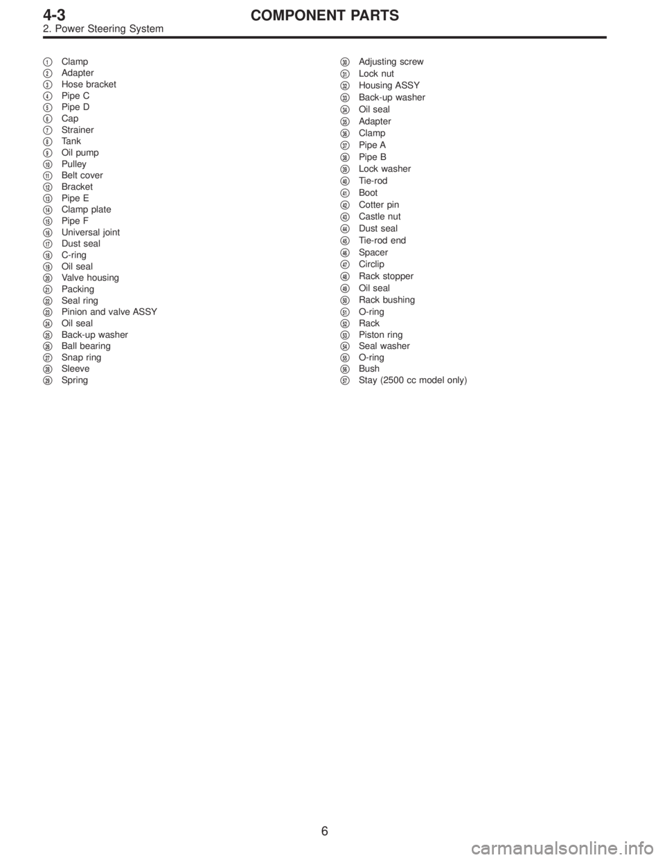
�1Clamp
�
2Adapter
�
3Hose bracket
�
4Pipe C
�
5Pipe D
�
6Cap
�
7Strainer
�
8Tank
�
9Oil pump
�
10Pulley
�
11Belt cover
�
12Bracket
�
13Pipe E
�
14Clamp plate
�
15Pipe F
�
16Universal joint
�
17Dust seal
�
18C-ring
�
19Oil seal
�
20Valve housing
�
21Packing
�
22Seal ring
�
23Pinion and valve ASSY
�
24Oil seal
�
25Back-up washer
�
26Ball bearing
�
27Snap ring
�
28Sleeve
�
29Spring�
30Adjusting screw
�
31Lock nut
�
32Housing ASSY
�
33Back-up washer
�
34Oil seal
�
35Adapter
�
36Clamp
�
37Pipe A
�
38Pipe B
�
39Lock washer
�
40Tie-rod
�
41Boot
�
42Cotter pin
�
43Castle nut
�
44Dust seal
�
45Tie-rod end
�
46Spacer
�
47Circlip
�
48Rack stopper
�
49Oil seal
�
50Rack bushing
�
51O-ring
�
52Rack
�
53Piston ring
�
54Seal washer
�
55O-ring
�
56Bush
�
57Stay (2500 cc model only)
6
4-3COMPONENT PARTS
2. Power Steering System
Page 1114 of 2890
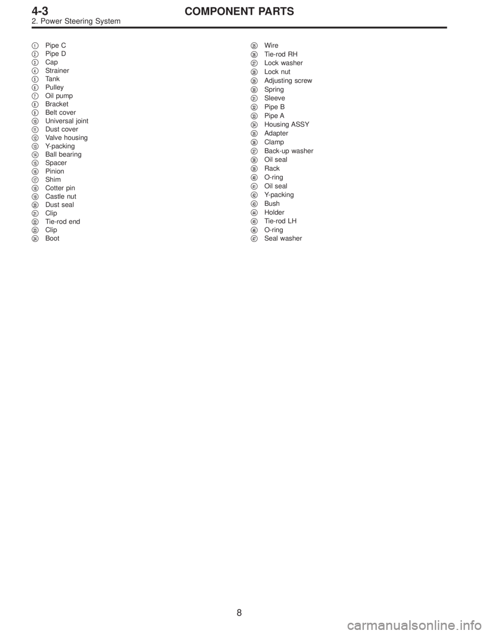
�1Pipe C
�
2Pipe D
�
3Cap
�
4Strainer
�
5Tank
�
6Pulley
�
7Oil pump
�
8Bracket
�
9Belt cover
�
10Universal joint
�
11Dust cover
�
12Valve housing
�
13Y-packing
�
14Ball bearing
�
15Spacer
�
16Pinion
�
17Shim
�
18Cotter pin
�
19Castle nut
�
20Dust seal
�
21Clip
�
22Tie-rod end
�
23Clip
�
24Boot�
25Wire
�
26Tie-rod RH
�
27Lock washer
�
28Lock nut
�
29Adjusting screw
�
30Spring
�
31Sleeve
�
32Pipe B
�
33Pipe A
�
34Housing ASSY
�
35Adapter
�
36Clamp
�
37Back-up washer
�
38Oil seal
�
39Rack
�
40O-ring
�
41Oil seal
�
42Y-packing
�
43Bush
�
44Holder
�
45Tie-rod LH
�
46O-ring
�
47Seal washer
8
4-3COMPONENT PARTS
2. Power Steering System
Page 1122 of 2890
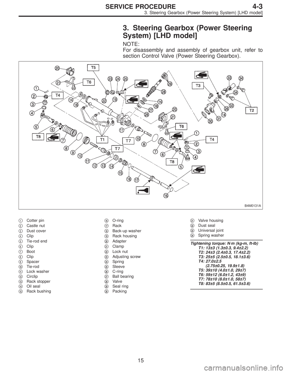
3. Steering Gearbox (Power Steering
System) [LHD model]
NOTE:
For disassembly and assembly of gearbox unit, refer to
section Control Valve (Power Steering Gearbox).
B4M0131A
�1Cotter pin
�
2Castle nut
�
3Dust cover
�
4Clip
�
5Tie-rod end
�
6Clip
�
7Boot
�
8Clip
�
9Spacer
�
10Tie-rod
�
11Lock washer
�
12Circlip
�
13Rack stopper
�
14Oil seal
�
15Rack bushing�
16O-ring
�
17Rack
�
18Back-up washer
�
19Rack housing
�
20Adapter
�
21Clamp
�
22Lock nut
�
23Adjusting screw
�
24Spring
�
25Sleeve
�
26C-ring
�
27Ball bearing
�
28Valve
�
29Seal ring
�
30Packing�
31Valve housing
�
32Dust seal
�
33Universal joint
�
34Spring washer
Tightening torque: N⋅m (kg-m, ft-lb)
T1: 13±3 (1.3±0.3, 9.4±2.2)
T2: 24±3 (2.4±0.3, 17.4±2.2)
T3: 25±5 (2.5±0.5, 18.1±3.6)
T4: 27.0±2.5
(2.75±0.25, 19.9±1.8)
T5: 39±10 (4.0±1.0, 29±7)
T6: 59±12 (6.0±1.2, 43±9)
T7: 78±10 (8.0±1.0, 58±7)
T8: 83±5 (8.5±0.5, 61.5±3.6)
15
4-3SERVICE PROCEDURE
3. Steering Gearbox (Power Steering System) [LHD model]
Page 1124 of 2890
G4M0101
9) Disconnect pipes C and D from pipe of gearbox.
CAUTION:
Be careful not to damage these pipes.
NOTE:
Disconnect upper pipe D first, and lower pipe C second.
G4M0102
10) Remove clamp bolts securing gearbox to
crossmember, and remove gearbox.
B4M0132A
B: DISASSEMBLY
1) Disconnect four pipes from gearbox.
2) Secure gearbox removed from vehicle in vice using ST.
ST 926200000 STAND
CAUTION:
Secure the gearbox in a vice using the ST as shown.
Do not attempt to secure it without this ST.
3) Remove tie-rod end and lock nut from gearbox.
G4M0104
4) Remove small clip from boot using pliers, and move
boot to tie-rod end side.
G4M0105
5) Remove boot together with large clips.
17
4-3SERVICE PROCEDURE
3. Steering Gearbox (Power Steering System) [LHD model]
Page 1126 of 2890
 Clean all disassembled parts, and check for wear,
damage, or any other faults, then repair or replace as nec-
essary.
2) When disassembling, check inside of gearbox for water.
If any")
C: INSPECTION
1) Clean all disassembled parts, and check for wear,
damage, or any other faults, then repair or replace as nec-
essary.
2) When disassembling, check inside of gearbox for water.
If any water is found, carefully check boot for damage,
input shaft dust seal, adjusting screw and boot clips for
poor sealing. If faulty, replace with new parts.
No. Parts Inspection Corrective action
1 Input shaft(1) Bend of input shaft
(2) Damage on serrationIf bend or damage is excessive, replace
entire gearbox.
2 Dust seal(1) Crack or damage
(2) WearIf outer wall slips, lip is worn out or
damage is found, replace it with new one.
3 Rack and pinion Poor mating of rack with pinion(1) Adjust backlash properly.
By measuring turning torque of
gearbox and sliding resistance of rack,
check if rack and pinion engage
uniformly and smoothly with each
other.
(Refer to“Service limit”.)
(2) Keeping rack pulled out all the way so
that all teeth emerge, check teeth for
damage.
Even if abnormality is found in either
(1) or (2), replace entire gearbox.
4 Gearbox unit(1) Bend of rack shaft
(2) Bend of cylinder portion
(3) Crack or damage on cast iron portionReplace gearbox with new one.
(4) Wear or damage on rack bushIf free play of rack shaft in radial direction
is out of the specified range, replace
gearbox with new one. (Refer to“Service
limit”.)
(5) Wear on input shaft bearingIf free plays of input shaft in radial and
axial directions are out of the specified
ranges, replace gearbox with new one.
(Refer to“Service limit”.)
5 Boot Crack, damage or deterioration Replace.
6 Tie-rod(1) Looseness of ball joint
(2) Bend of tie-rodReplace.
7 Tie-rod end Damage or deterioration on dust seal Replace.
8 Adjusting screw spring Deterioration Replace.
9 Boot clip Deterioration Replace.
10 Sleeve Damage Replace.
11 Pipes(1) Damage to flared surface
(2) Damage to flare nut
(3) Damage to pipe
(4) Damage to O-ringReplace.
19
4-3SERVICE PROCEDURE
3. Steering Gearbox (Power Steering System) [LHD model]
Page 1131 of 2890
![SUBARU LEGACY 1996 Service Repair Manual �Make adjustment so that steering wheel can be rotated
fully from lock to lock without binding.
9) Check for service limit as per article of“Service limit”.
<Ref. to 4-3 [W3C1].> Make replacement](/manual-img/17/57433/w960_57433-1130.png "SUBARU LEGACY 1996 Service Repair Manual �Make adjustment so that steering wheel can be rotated
fully from lock to lock without binding.
9) Check for service limit as per article of“Service limit”.
<Ref. to 4-3 [W3C1].> Make replacement")
�Make adjustment so that steering wheel can be rotated
fully from lock to lock without binding.
9) Check for service limit as per article of“Service limit”.
Make replacement and adjustment
if necessary.
10) Install boot and mounting rubber to housing.
NOTE:
Apply grease through small hole in boot.
G4M0123
11) Fit clip (large) to boot, and then install boot to gearbox
while holding boot flange.
After installing boot, fold back boot flange to the extent that
large clip can not be seen.
NOTE:
�Before installing boot, be sure to apply grease to the
groove of tie-rod.
�Install fitting portions of boots to the following portions in
both sides of assembled steering gearbox.
1. The groove on gearbox
2. The groove on the rod
�Make sure that boot is installed without unusual inflation
or deflation.
G4M0124
12) Turn boot until it seats well on gearbox and rubber
mounting, then bend boot flange back.
G4M0125
13) Fix boot end with clip (small).
CAUTION:
Use screwdriver with blunted tip to prevent boot from
damage, when installing.
NOTE:
After installing, check boot end is positioned into groove on
tie-rod.
24
4-3SERVICE PROCEDURE
3. Steering Gearbox (Power Steering System) [LHD model]
Page 1132 of 2890
 If tie-rod end was removed, screw in lock nut and tie-
rod end to screwed portion of tie-rod, and tighten lock nut
temporarily in a position as shown in figure.
Installed tie-rod length: L")
G4M0126
14) If tie-rod end was removed, screw in lock nut and tie-
rod end to screwed portion of tie-rod, and tighten lock nut
temporarily in a position as shown in figure.
Installed tie-rod length: L
15 mm (0.59 in)
NOTE:
Pay attention to difference between right and left tie-rod
ends.
G4M0127
15) Inspect gearbox as follows:
A. Holding tie-rod end, repeat lock to lock two or three
times as quickly as possible.
B. Holding tie-rod end, turn it slowly at a radius one or two
times as large as possible.
After all, make sure that boot is installed in the specified
position without deflation.
16) Remove gearbox from ST.
ST 926200000 STAND
17) Install four pipes on gearbox.
(1) Connect pipes A and B to four pipe joints of gear-
box. Connect upper pipe B first, and lower pipe A.
Tightening torque:
13±3 N⋅m (1.3±0.3 kg-m, 9.4±2.2 ft-lb)
G4M0101
(2) Connect pipes C and D to gearbox.
Connect lower pipe C first, and upper pipe D second.
Tightening torque:
15±5 N⋅m (1.5±0.5 kg-m, 10.8±3.6 ft-lb)
G4M0102
E: INSTALLATION
1) Insert gearbox into crossmember, being careful not to
damage gearbox boot.
2) Tighten gearbox to crossmember bracket via clamp with
bolt to the specified torque.
Tightening torque:
59±12 N⋅m (6.0±1.2 kg-m, 43±9 ft-lb)
25
4-3SERVICE PROCEDURE
3. Steering Gearbox (Power Steering System) [LHD model]
Page 1134 of 2890
G4M0132
15) After adjusting toe-in and steering angle, tighten lock
nut on tie-rod end.
Tightening torque:
83±5 N⋅m (8.5±0.5 kg-m, 61.5±3.6 ft-lb)
CAUTION:
When adjusting toe-in, hold boot as shown to prevent
it from being rotated or twisted. If twisted, straighten it.
G4M0133
F: ADJUSTMENT
1) Adjust front toe.
Standard of front toe:
IN 3—OUT 3 mm (IN 0.12—OUT 0.12 in)
2) Adjust steering angle of wheels.
Inner wheel: 37.6°±1.5
Outer wheel: 32.6°±1.5
B4M0133A
3) If steering wheel spokes are not horizontal when wheels
are set in the straight ahead position, and error is more
than 5°on the periphery of steering wheel, correctly re-in-
stall the steering wheel.
G4M0135
4) If steering wheel spokes are not horizontal with vehicle
set in the straight ahead position after this adjustment,
correct it by turning the right and left tie-rods in the same
direction by the same turns.
27
4-3SERVICE PROCEDURE
3. Steering Gearbox (Power Steering System) [LHD model]
 Disconnect pipes C and D from pipe of gearbox.
CAUTION:
Be careful not to damage these pipes.
NOTE:
Disconnect upper pipe D first, and lower pipe C second.
G4M0102
10) Remove clamp bolts se")
 After adjusting toe-in and steering angle, tighten lock
nut on tie-rod end.
Tightening torque:
83±5 N⋅m (8.5±0.5 kg-m, 61.5±3.6 ft-lb)
CAUTION:
When adjusting toe-in, hold boot as sho")