Page 2118 of 2890
![SUBARU LEGACY 1996 Service Repair Manual B6M0121
10BP11CHECK HARNESS BETWEEN COMBINA-
TION METER AND FUEL PUMP CONNEC-
TOR.
1) Connect connector to fuel pump.
2) Pull out combination meter from instrument panel. <Ref.
to 6-2 [W13A1].>
3) Dis](/manual-img/17/57433/w960_57433-2117.png "SUBARU LEGACY 1996 Service Repair Manual B6M0121
10BP11CHECK HARNESS BETWEEN COMBINA-
TION METER AND FUEL PUMP CONNEC-
TOR.
1) Connect connector to fuel pump.
2) Pull out combination meter from instrument panel. <Ref.
to 6-2 [W13A1].>
3) Dis")
B6M0121
10BP11CHECK HARNESS BETWEEN COMBINA-
TION METER AND FUEL PUMP CONNEC-
TOR.
1) Connect connector to fuel pump.
2) Pull out combination meter from instrument panel.
to 6-2 [W13A1].>
3) Disconnect connector from combination meter.
B2M0945A
4) Measure resistance of harness between combination
meter connector and chassis ground.
: Connector & terminal
(i10) No. 3—Chassis ground:
Is the resistance less than 200Ω?
: Go to step10BP12.
: Repair harness and connector.
NOTE:
In this case, repair the following:
�Open circuit in harness between combination meter con-
nector and junction A on rear wiring harness
�Poor contact in coupling connectors (i3, and B99 (LHD)/
B97 (RHD))
10BP12
CHECK COMBINATION METER.
1) Disconnect speedometer cable from combination meter
and remove combination meter.
: Is the fuel meter installation screw tightened
securely?
: Go to next step 2).
: Tighten fuel meter installation screw securely.
2) Remove printed circuit plate assembly from combina-
tion meter assembly.
: Is there flaw or burning on printed circuit
plate assembly?
: Replace printed circuit plate assembly.
: Replace fuel meter assembly.
350
2-7ON-BOARD DIAGNOSTICS II SYSTEM
10. Diagnostics Chart with Trouble Code
Page 2121 of 2890
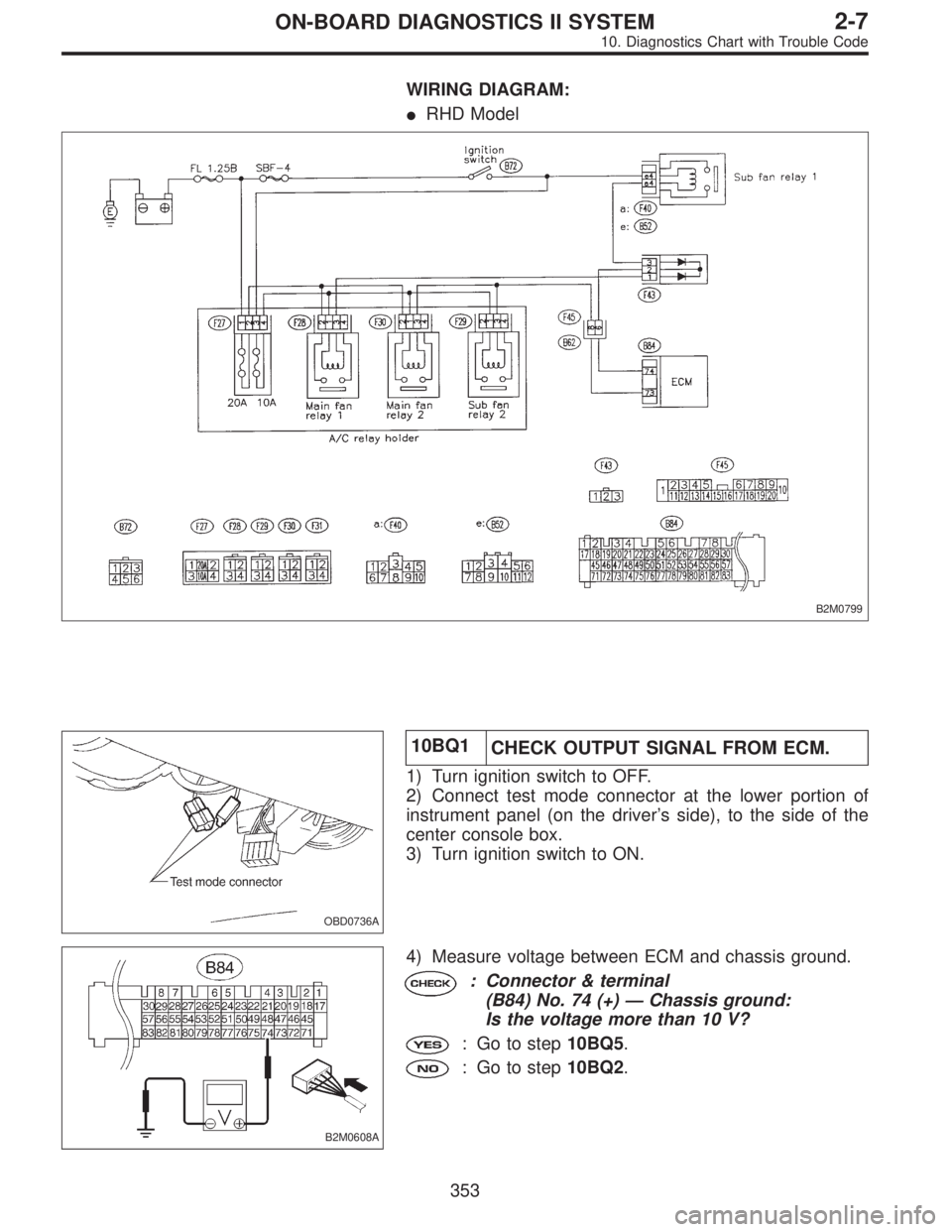
WIRING DIAGRAM:
�RHD Model
B2M0799
OBD0736A
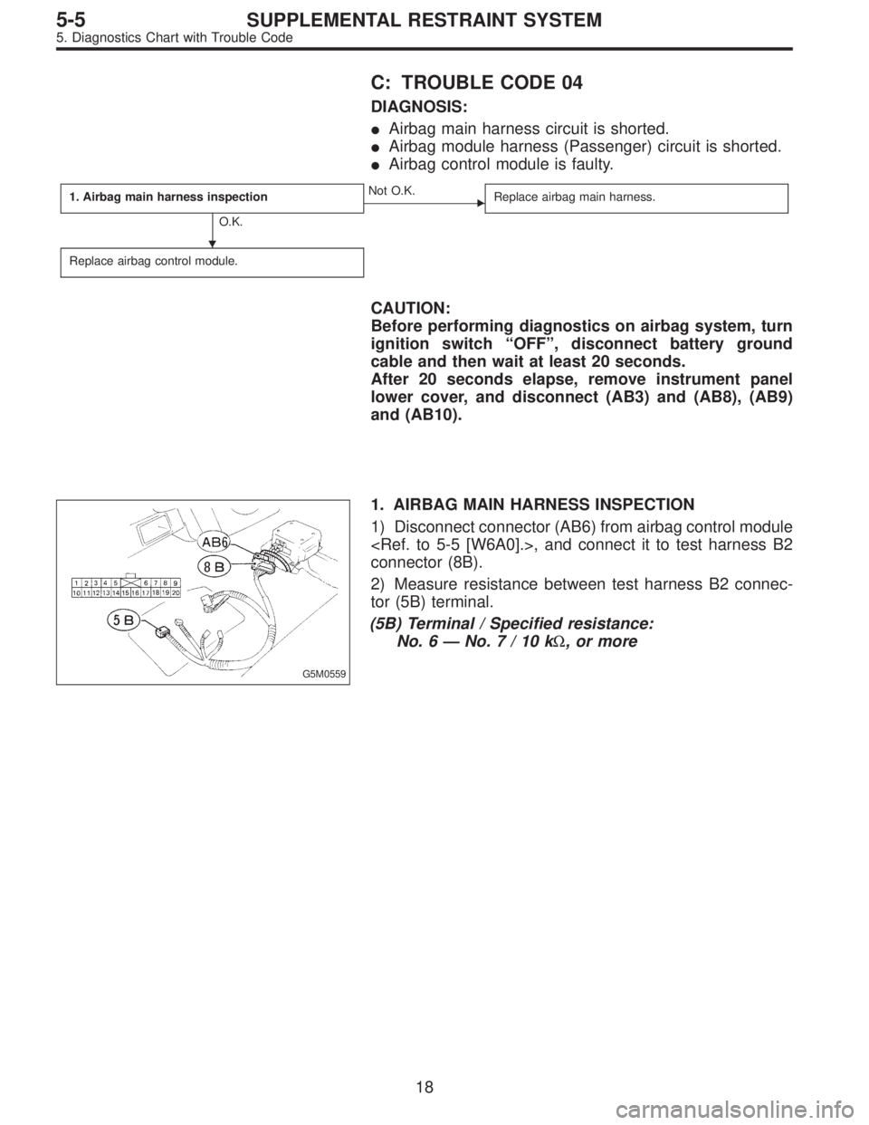
10BQ1
CHECK OUTPUT SIGNAL FROM ECM.
1) Turn ignition switch to OFF.
2) Connect test mode connector at the lower portion of
instrument panel (on the driver’s side), to the side of the
center console box.
3) Turn ignition switch to ON.
B2M0608A
4) Measure voltage between ECM and chassis ground.
: Connector & terminal
(B84) No. 74 (+)—Chassis ground:
Is the voltage more than 10 V?
: Go to step10BQ5.
: Go to step10BQ2.
353
2-7ON-BOARD DIAGNOSTICS II SYSTEM
10. Diagnostics Chart with Trouble Code
Page 2629 of 2890
C: TROUBLE CODE 04
DIAGNOSIS:
�Airbag main harness circuit is shorted.
�Airbag module harness (Passenger) circuit is shorted.
�Airbag control module is faulty.
1. Airbag main harness inspection
O.K.
�Not O.K.
Replace airbag main harness.
Replace airbag control module.
CAUTION:
Before performing diagnostics on airbag system, turn
ignition switch“OFF”, disconnect battery ground
cable and then wait at least 20 seconds.
After 20 seconds elapse, remove instrument panel
lower cover, and disconnect (AB3) and (AB8), (AB9)
and (AB10).
G5M0559
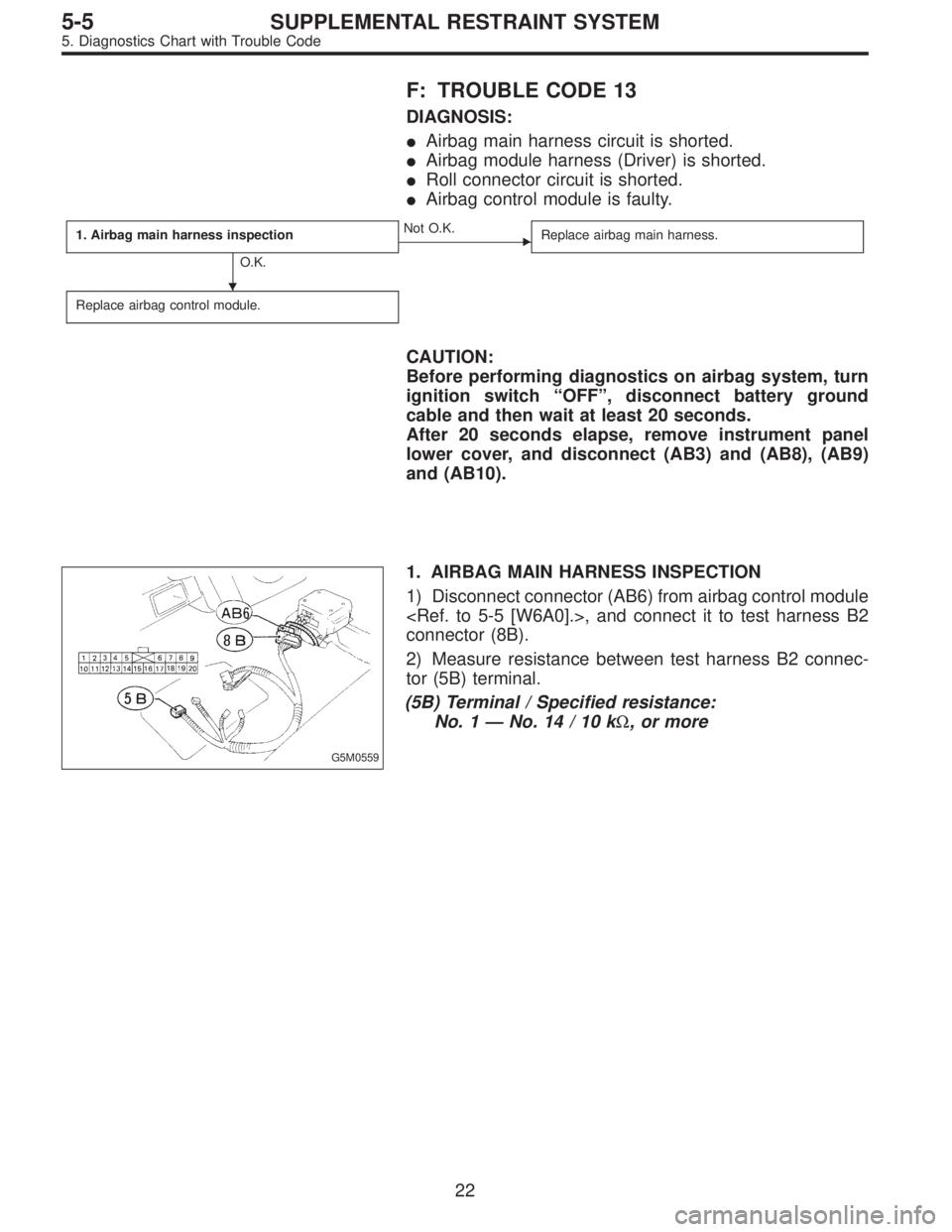
1. AIRBAG MAIN HARNESS INSPECTION
1) Disconnect connector (AB6) from airbag control module
, and connect it to test harness B2
connector (8B).
2) Measure resistance between test harness B2 connec-
tor (5B) terminal.
(5B) Terminal / Specified resistance:
No. 6—No.7/10kΩ, or more
�
18
5-5SUPPLEMENTAL RESTRAINT SYSTEM
5. Diagnostics Chart with Trouble Code
Page 2630 of 2890

D: TROUBLE CODE 11
DIAGNOSIS:
�Airbag control module is faulty.
�Airbag main harness circuit is open.
�Fuse No. 8 is blown.
�Body harness circuit is open.
1. Airbag control module inspection
Not O.K.
�O.K.
Replace airbag control module.
2. Airbag main harness inspection
O.K.
�Not O.K.
Replace airbag main harness.
3. Fuse No. 8 inspection
O.K.
�Not O.K.
Replace fuse No. 8.
Repair body harness.
CAUTION:
Before performing diagnostics on airbag system, turn
ignition switch“OFF”, disconnect battery ground
cable and then wait at least 20 seconds.
After 20 seconds elapse, remove instrument panel
lower cover, and disconnect (AB3) and (AB8), (AB9)
and (AB10).
G5M0559
1. AIRBAG CONTROL MODULE INSPECTION
1) Disconnect connector (AB6) from airbag control module
and connect it to test harness B2
connector (8B).
2) Connect battery ground cable and turn ignition switch
“ON”. (engine off)
3) Measure voltage across connector (5B) terminal and
body.
(5B) Terminal / Specified voltage:
No. 2—Body / 10 V, or more
2. AIRBAG MAIN HARNESS INSPECTION
1) Go to step 2) below after performing diagnostics on air-
bag system as per flowchart under“1. AIRBAG CON-
TROL MODULE INSPECTION”previously outlined.
2) Turn ignition switch“OFF”, disconnect battery ground
terminal and then wait at least 20 seconds.
�
�
�
19
5-5SUPPLEMENTAL RESTRAINT SYSTEM
5. Diagnostics Chart with Trouble Code
Page 2633 of 2890
F: TROUBLE CODE 13
DIAGNOSIS:
�Airbag main harness circuit is shorted.
�Airbag module harness (Driver) is shorted.
�Roll connector circuit is shorted.
�Airbag control module is faulty.
1. Airbag main harness inspection
O.K.
�Not O.K.
Replace airbag main harness.
Replace airbag control module.
CAUTION:
Before performing diagnostics on airbag system, turn
ignition switch“OFF”, disconnect battery ground
cable and then wait at least 20 seconds.
After 20 seconds elapse, remove instrument panel
lower cover, and disconnect (AB3) and (AB8), (AB9)
and (AB10).
G5M0559
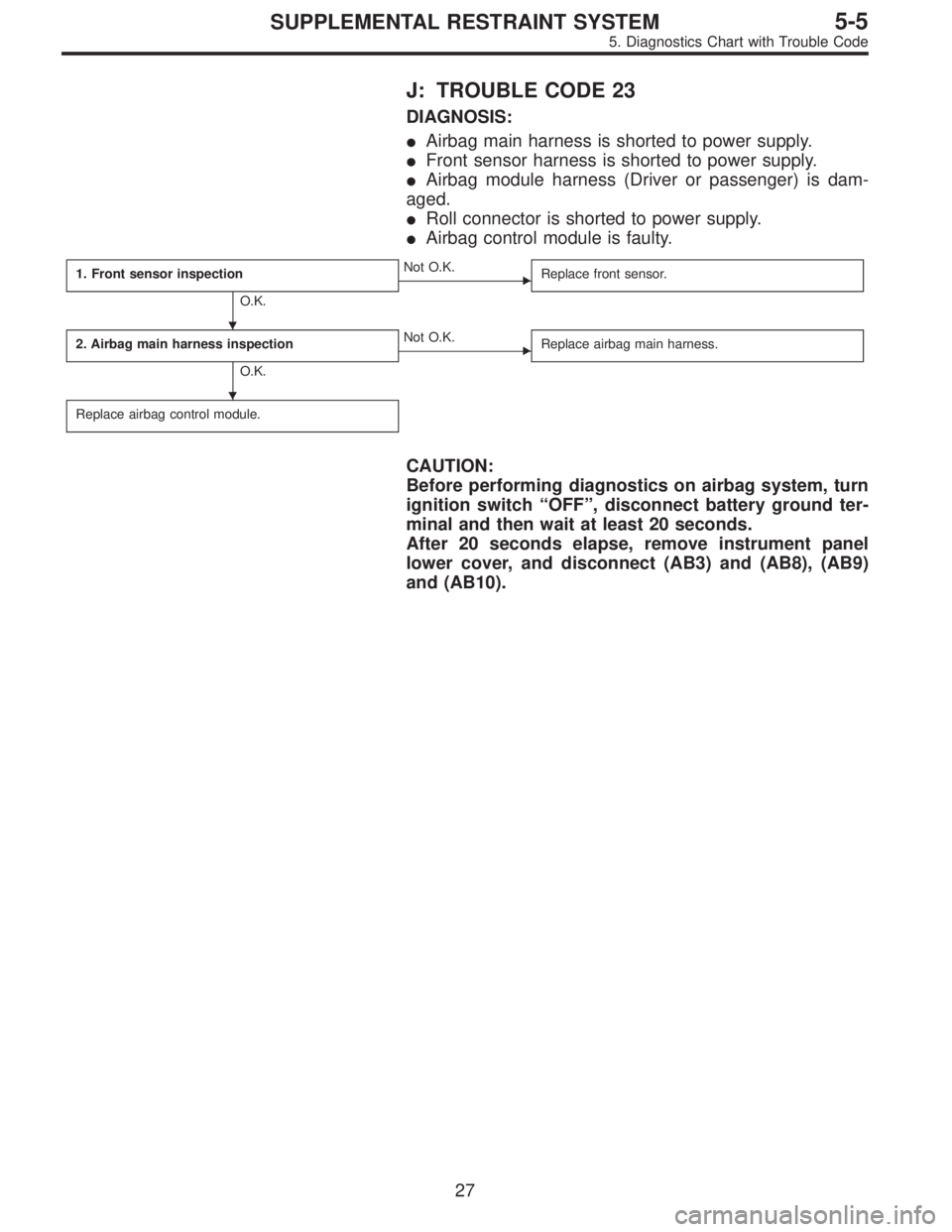
1. AIRBAG MAIN HARNESS INSPECTION
1) Disconnect connector (AB6) from airbag control module
, and connect it to test harness B2
connector (8B).
2) Measure resistance between test harness B2 connec-
tor (5B) terminal.
(5B) Terminal / Specified resistance:
No. 1—No.14/10kΩ, or more
�
22
5-5SUPPLEMENTAL RESTRAINT SYSTEM
5. Diagnostics Chart with Trouble Code
Page 2638 of 2890
J: TROUBLE CODE 23
DIAGNOSIS:
�Airbag main harness is shorted to power supply.
�Front sensor harness is shorted to power supply.
�Airbag module harness (Driver or passenger) is dam-
aged.
�Roll connector is shorted to power supply.
�Airbag control module is faulty.
1. Front sensor inspection
O.K.
�Not O.K.
Replace front sensor.
2. Airbag main harness inspection
O.K.
�Not O.K.
Replace airbag main harness.
Replace airbag control module.
CAUTION:
Before performing diagnostics on airbag system, turn
ignition switch“OFF”, disconnect battery ground ter-
minal and then wait at least 20 seconds.
After 20 seconds elapse, remove instrument panel
lower cover, and disconnect (AB3) and (AB8), (AB9)
and (AB10).
�
�
27
5-5SUPPLEMENTAL RESTRAINT SYSTEM
5. Diagnostics Chart with Trouble Code
Page 2642 of 2890
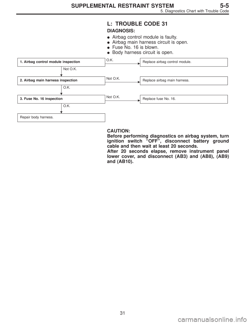
L: TROUBLE CODE 31
DIAGNOSIS:
�Airbag control module is faulty.
�Airbag main harness circuit is open.
�Fuse No. 16 is blown.
�Body harness circuit is open.
1. Airbag control module inspection
Not O.K.
�O.K.
Replace airbag control module.
2. Airbag main harness inspection
O.K.
�Not O.K.
Replace airbag main harness.
3. Fuse No. 16 inspection
O.K.
�Not O.K.
Replace fuse No. 16.
Repair body harness.
CAUTION:
Before performing diagnostics on airbag system, turn
ignition switch“OFF”, disconnect battery ground
cable and then wait at least 20 seconds.
After 20 seconds elapse, remove instrument panel
lower cover, and disconnect (AB3) and (AB8), (AB9)
and (AB10).
�
�
�
31
5-5SUPPLEMENTAL RESTRAINT SYSTEM
5. Diagnostics Chart with Trouble Code
Page 2647 of 2890
 Turn ignition switch“OFF”and connect body harness
connector (B31) to test connector A connector (1A).
G5M0455
2) Conne")
B5M0123B
2. INSPECTION OF BODY HARNESS, CONNECTOR
AND AIRBAG WARNING LIGHT
1) Turn ignition switch“OFF”and connect body harness
connector (B31) to test connector A connector (1A).
G5M0455
2) Connect battery ground cable and turn ignition switch
“ON”, (engine off) and connect connectors (3A) and (4A) to
check if warning light goes out. If it does, go to step 4)
below. If it remains on, check body harness and repair if
necessary.
B5M0124A
3) If body harness is satisfactory, replace airbag warning
light module�
1. After problem has been eliminated, discon-
nect connectors (3A) and (4A).
G5M0559
4) Turn ignition switch“OFF”, disconnect battery ground
cable and then wait at least 20 seconds, and re-connect
connectors (AB1) and (B31).
5) Remove instrument panel lower cover and disconnect
(AB3) with (AB8), then disconnect connector (AB6) from
airbag control module, and connect
it to test harness B2 connector (8B).
G5M0458
6) Connect battery ground cable and turn ignition switch
“ON,”(engine off) and connect connectors (6B) and (7B) to
check if warning light goes out. If it does, go to“3.
GROUNDING CIRCUIT INSPECTION”. If it remains on,
replace airbag main harness. After problem has been
eliminated, disconnect connectors (6B) and (7B).
36
5-5SUPPLEMENTAL RESTRAINT SYSTEM
5. Diagnostics Chart with Trouble Code