Page 1708 of 2890
B6M0144A
3. SUNROOF RELAY
Check continuity between terminals as indicated in table
below, when battery voltage is applied between terminals
No. 1 and No. 3.
When current flows. Between terminals
No. 2 and No. 4Continuity exists.
When current does not flow. Between terminals
No. 2 and No. 4Continuity does not
exist.
Between terminals
No. 1 and No. 3Continuity exists.
B6M0354
20. Radio, Speaker and Antenna
A: REMOVAL AND INSTALLATION
1. RADIO BODY
1) Remove hand brake cover.
2) Remove console cover.
3) Remove screws which secure center panel. Remove
center panel.
B6M0355
4) Remove fitting screws, and slightly pull radio out of
instrument panel.
5) Disconnect connectors and antenna feeder cord.
B6M0146
2. FRONT SPEAKER
1) Remove gusset speaker from behind the rearview mir-
ror while disconnecting connector.
2) Remove door trim panel.
45
6-2SERVICE PROCEDURE
19. Sunroof - 20. Radio, Speaker and Antenna
Page 1709 of 2890
B6M0144A
3. SUNROOF RELAY
Check continuity between terminals as indicated in table
below, when battery voltage is applied between terminals
No. 1 and No. 3.
When current flows. Between terminals
No. 2 and No. 4Continuity exists.
When current does not flow. Between terminals
No. 2 and No. 4Continuity does not
exist.
Between terminals
No. 1 and No. 3Continuity exists.
B6M0354
20. Radio, Speaker and Antenna
A: REMOVAL AND INSTALLATION
1. RADIO BODY
1) Remove hand brake cover.
2) Remove console cover.
3) Remove screws which secure center panel. Remove
center panel.
B6M0355
4) Remove fitting screws, and slightly pull radio out of
instrument panel.
5) Disconnect connectors and antenna feeder cord.
B6M0146
2. FRONT SPEAKER
1) Remove gusset speaker from behind the rearview mir-
ror while disconnecting connector.
2) Remove door trim panel.
45
6-2SERVICE PROCEDURE
19. Sunroof - 20. Radio, Speaker and Antenna
Page 1712 of 2890
B6M0154A
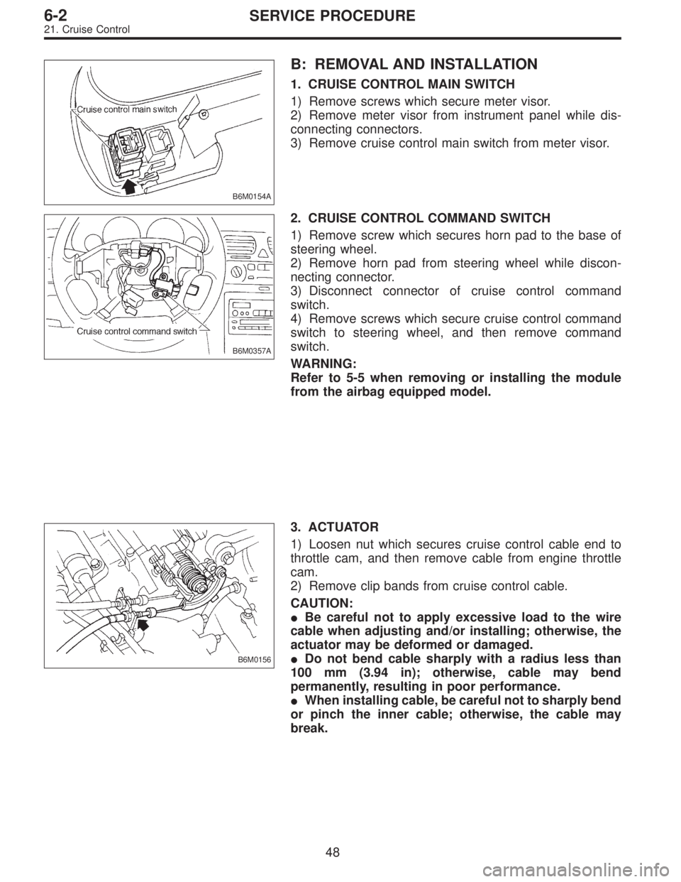
B: REMOVAL AND INSTALLATION
1. CRUISE CONTROL MAIN SWITCH
1) Remove screws which secure meter visor.
2) Remove meter visor from instrument panel while dis-
connecting connectors.
3) Remove cruise control main switch from meter visor.
B6M0357A
2. CRUISE CONTROL COMMAND SWITCH
1) Remove screw which secures horn pad to the base of
steering wheel.
2) Remove horn pad from steering wheel while discon-
necting connector.
3) Disconnect connector of cruise control command
switch.
4) Remove screws which secure cruise control command
switch to steering wheel, and then remove command
switch.
WARNING:
Refer to 5-5 when removing or installing the module
from the airbag equipped model.
B6M0156
3. ACTUATOR
1) Loosen nut which secures cruise control cable end to
throttle cam, and then remove cable from engine throttle
cam.
2) Remove clip bands from cruise control cable.
CAUTION:
�Be careful not to apply excessive load to the wire
cable when adjusting and/or installing; otherwise, the
actuator may be deformed or damaged.
�Do not bend cable sharply with a radius less than
100 mm (3.94 in); otherwise, cable may bend
permanently, resulting in poor performance.
�When installing cable, be careful not to sharply bend
or pinch the inner cable; otherwise, the cable may
break.
48
6-2SERVICE PROCEDURE
21. Cruise Control
Page 1716 of 2890
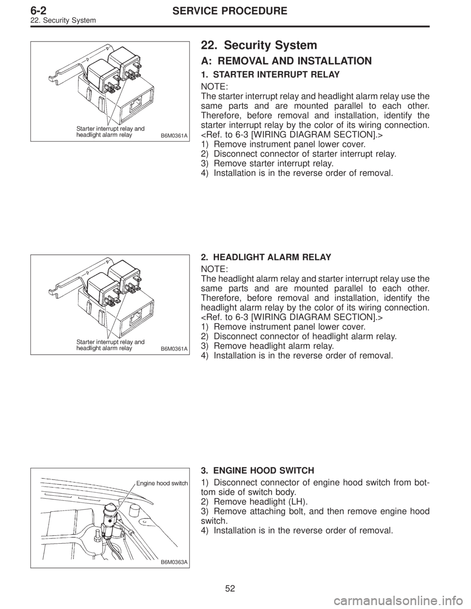
B6M0361A
22. Security System
A: REMOVAL AND INSTALLATION
1. STARTER INTERRUPT RELAY
NOTE:
The starter interrupt relay and headlight alarm relay use the
same parts and are mounted parallel to each other.
Therefore, before removal and installation, identify the
starter interrupt relay by the color of its wiring connection.
1) Remove instrument panel lower cover.
2) Disconnect connector of starter interrupt relay.
3) Remove starter interrupt relay.
4) Installation is in the reverse order of removal.
B6M0361A
2. HEADLIGHT ALARM RELAY
NOTE:
The headlight alarm relay and starter interrupt relay use the
same parts and are mounted parallel to each other.
Therefore, before removal and installation, identify the
headlight alarm relay by the color of its wiring connection.
1) Remove instrument panel lower cover.
2) Disconnect connector of headlight alarm relay.
3) Remove headlight alarm relay.
4) Installation is in the reverse order of removal.
B6M0363A
3. ENGINE HOOD SWITCH
1) Disconnect connector of engine hood switch from bot-
tom side of switch body.
2) Remove headlight (LH).
3) Remove attaching bolt, and then remove engine hood
switch.
4) Installation is in the reverse order of removal.
52
6-2SERVICE PROCEDURE
22. Security System
Page 1719 of 2890
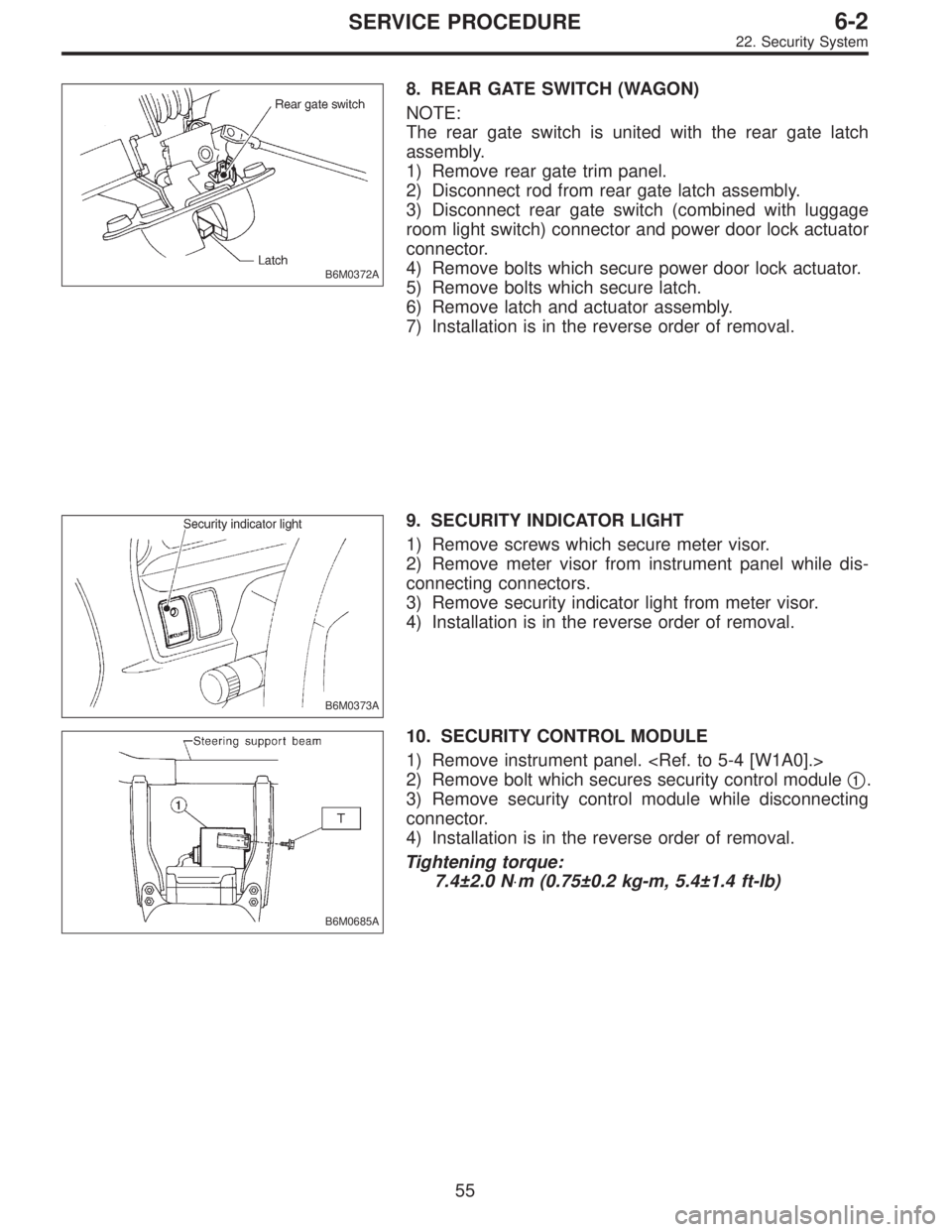
B6M0372A
8. REAR GATE SWITCH (WAGON)
NOTE:
The rear gate switch is united with the rear gate latch
assembly.
1) Remove rear gate trim panel.
2) Disconnect rod from rear gate latch assembly.
3) Disconnect rear gate switch (combined with luggage
room light switch) connector and power door lock actuator
connector.
4) Remove bolts which secure power door lock actuator.
5) Remove bolts which secure latch.
6) Remove latch and actuator assembly.
7) Installation is in the reverse order of removal.
B6M0373A
9. SECURITY INDICATOR LIGHT
1) Remove screws which secure meter visor.
2) Remove meter visor from instrument panel while dis-
connecting connectors.
3) Remove security indicator light from meter visor.
4) Installation is in the reverse order of removal.
B6M0685A
10. SECURITY CONTROL MODULE
1) Remove instrument panel.
2) Remove bolt which secures security control module�
1.
3) Remove security control module while disconnecting
connector.
4) Installation is in the reverse order of removal.
Tightening torque:
7.4±2.0 N⋅m (0.75±0.2 kg-m, 5.4±1.4 ft-lb)
55
6-2SERVICE PROCEDURE
22. Security System
Page 1797 of 2890
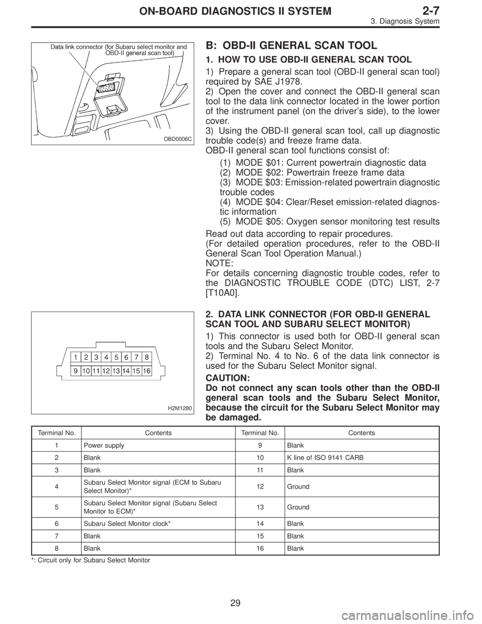
OBD0006C
B: OBD-II GENERAL SCAN TOOL
1. HOW TO USE OBD-II GENERAL SCAN TOOL
1) Prepare a general scan tool (OBD-II general scan tool)
required by SAE J1978.
2) Open the cover and connect the OBD-II general scan
tool to the data link connector located in the lower portion
of the instrument panel (on the driver’s side), to the lower
cover.
3) Using the OBD-II general scan tool, call up diagnostic
trouble code(s) and freeze frame data.
OBD-II general scan tool functions consist of:
(1) MODE $01: Current powertrain diagnostic data
(2) MODE $02: Powertrain freeze frame data
(3) MODE $03: Emission-related powertrain diagnostic
trouble codes
(4) MODE $04: Clear/Reset emission-related diagnos-
tic information
(5) MODE $05: Oxygen sensor monitoring test results
Read out data according to repair procedures.
(For detailed operation procedures, refer to the OBD-II
General Scan Tool Operation Manual.)
NOTE:
For details concerning diagnostic trouble codes, refer to
the DIAGNOSTIC TROUBLE CODE (DTC) LIST, 2-7
[T10A0].
H2M1280
2. DATA LINK CONNECTOR (FOR OBD-II GENERAL
SCAN TOOL AND SUBARU SELECT MONITOR)
1) This connector is used both for OBD-II general scan
tools and the Subaru Select Monitor.
2) Terminal No. 4 to No. 6 of the data link connector is
used for the Subaru Select Monitor signal.
CAUTION:
Do not connect any scan tools other than the OBD-II
general scan tools and the Subaru Select Monitor,
because the circuit for the Subaru Select Monitor may
be damaged.
Terminal No. Contents Terminal No. Contents
1 Power supply 9 Blank
2 Blank 10 K line of ISO 9141 CARB
3 Blank 11 Blank
4Subaru Select Monitor signal (ECM to Subaru
Select Monitor)*12 Ground
5Subaru Select Monitor signal (Subaru Select
Monitor to ECM)*13 Ground
6 Subaru Select Monitor clock* 14 Blank
7 Blank 15 Blank
8 Blank 16 Blank
*: Circuit only for Subaru Select Monitor
29
2-7ON-BOARD DIAGNOSTICS II SYSTEM
3. Diagnosis System
Page 1800 of 2890
OBD0057A
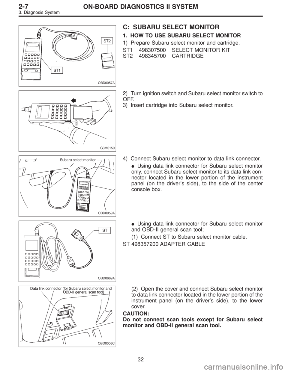
C: SUBARU SELECT MONITOR
1. HOW TO USE SUBARU SELECT MONITOR
1) Prepare Subaru select monitor and cartridge.
ST1 498307500 SELECT MONITOR KIT
ST2 498345700 CARTRIDGE
G3M0150
2) Turn ignition switch and Subaru select monitor switch to
OFF.
3) Insert cartridge into Subaru select monitor.
OBD0059A
4) Connect Subaru select monitor to data link connector.
�Using data link connector for Subaru select monitor
only, connect Subaru select monitor to its data link con-
nector located in the lower portion of the instrument
panel (on the driver’s side), to the side of the center
console box.
OBD0669A
�Using data link connector for Subaru select monitor
and OBD-II general scan tool;
(1) Connect ST to Subaru select monitor cable.
ST 498357200 ADAPTER CABLE
OBD0006C
(2) Open the cover and connect Subaru select monitor
to data link connector located in the lower portion of the
instrument panel (on the driver’s side), to the lower
cover.
CAUTION:
Do not connect scan tools except for Subaru select
monitor and OBD-II general scan tool.
32
2-7ON-BOARD DIAGNOSTICS II SYSTEM
3. Diagnosis System
Page 1828 of 2890
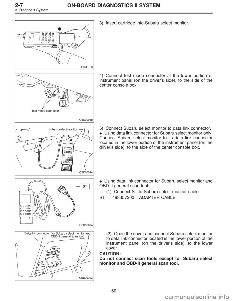
G3M0150
3) Insert cartridge into Subaru select monitor.
OBD0005B
4) Connect test mode connector at the lower portion of
instrument panel (on the driver’s side), to the side of the
center console box.
OBD0059A
5) Connect Subaru select monitor to data link connector.
�Using data link connector for Subaru select monitor only:
Connect Subaru select monitor to its data link connector
located in the lower portion of the instrument panel (on the
driver’s side), to the side of the center console box.
OBD0669A
�Using data link connector for Subaru select monitor and
OBD-II general scan tool:
(1) Connect ST to Subaru select monitor cable.
ST 498357200 ADAPTER CABLE
OBD0006C
(2) Open the cover and connect Subaru select monitor
to data link connector located in the lower portion of the
instrument panel (on the driver’s side), to the lower
cover.
CAUTION:
Do not connect scan tools except for Subaru select
monitor and OBD-II general scan tool.
60
2-7ON-BOARD DIAGNOSTICS II SYSTEM
3. Diagnosis System