Page 1563 of 2890
1. Instrument Panel
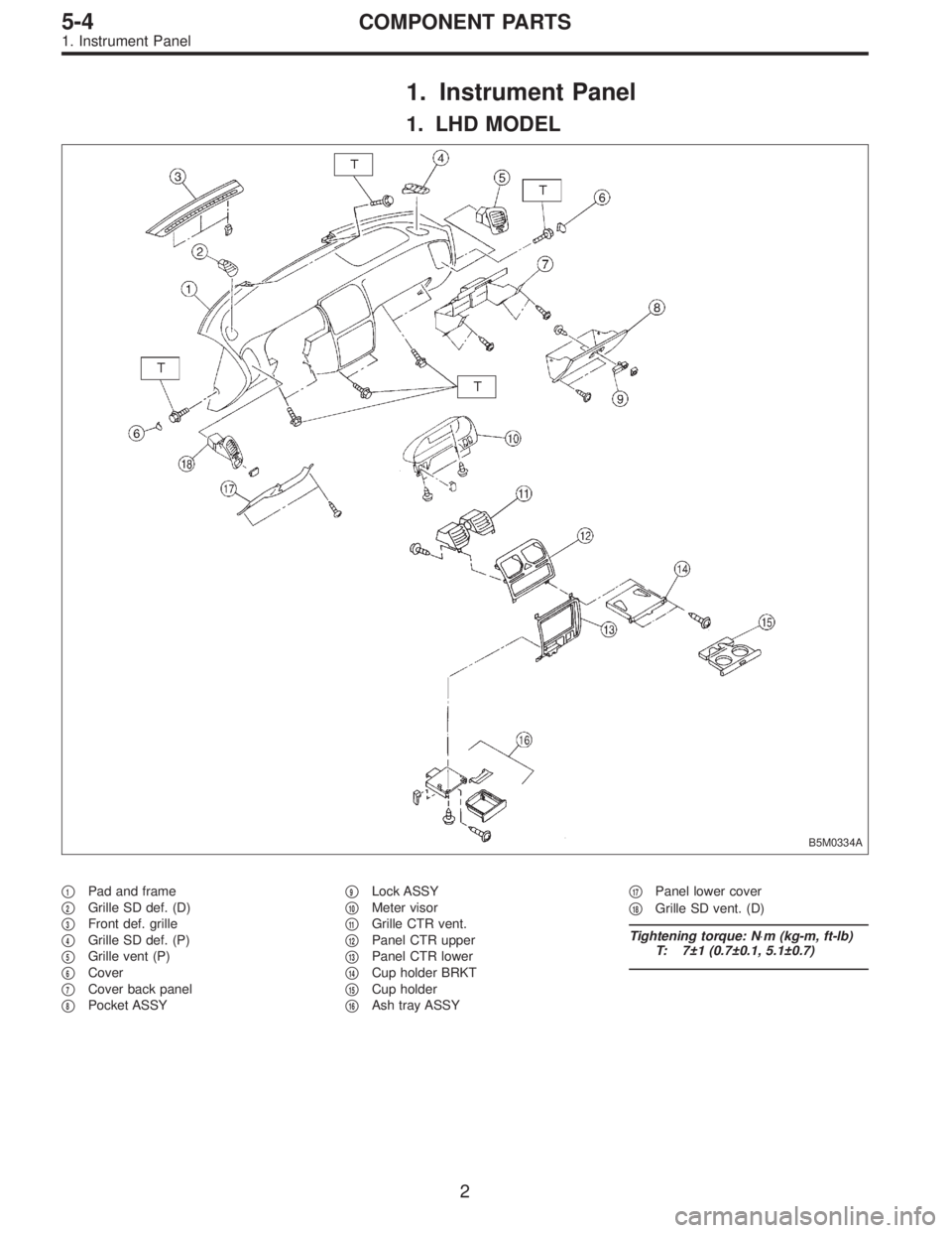
1. LHD MODEL
B5M0334A
�1Pad and frame
�
2Grille SD def. (D)
�
3Front def. grille
�
4Grille SD def. (P)
�
5Grille vent (P)
�
6Cover
�
7Cover back panel
�
8Pocket ASSY�
9Lock ASSY
�
10Meter visor
�
11Grille CTR vent.
�
12Panel CTR upper
�
13Panel CTR lower
�
14Cup holder BRKT
�
15Cup holder
�
16Ash tray ASSY�
17Panel lower cover
�
18Grille SD vent. (D)
Tightening torque: N⋅m (kg-m, ft-lb)
T: 7±1 (0.7±0.1, 5.1±0.7)
2
5-4COMPONENT PARTS
1. Instrument Panel
Page 1564 of 2890
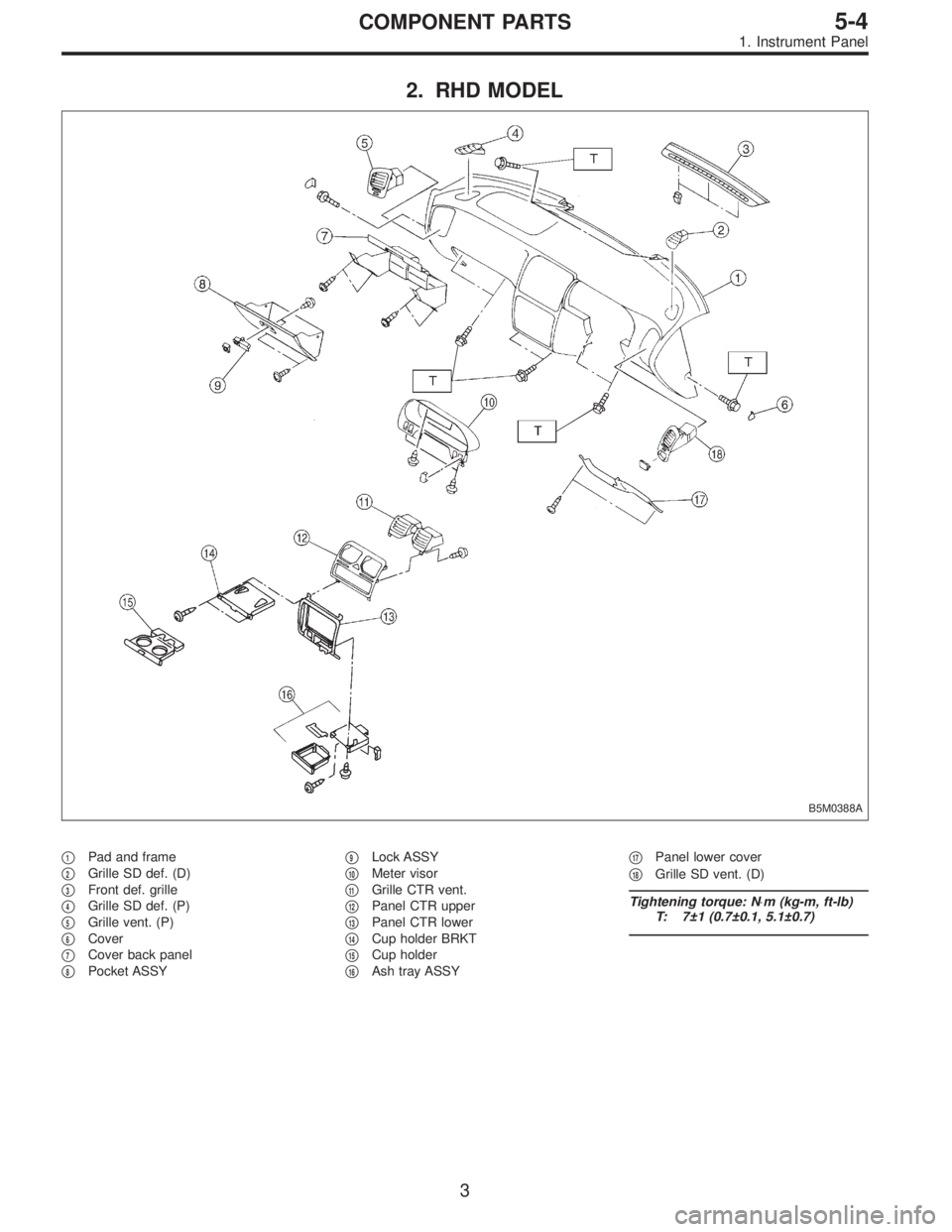
2. RHD MODEL
B5M0388A
�1Pad and frame
�
2Grille SD def. (D)
�
3Front def. grille
�
4Grille SD def. (P)
�
5Grille vent. (P)
�
6Cover
�
7Cover back panel
�
8Pocket ASSY�
9Lock ASSY
�
10Meter visor
�
11Grille CTR vent.
�
12Panel CTR upper
�
13Panel CTR lower
�
14Cup holder BRKT
�
15Cup holder
�
16Ash tray ASSY�
17Panel lower cover
�
18Grille SD vent. (D)
Tightening torque: N⋅m (kg-m, ft-lb)
T: 7±1 (0.7±0.1, 5.1±0.7)
3
5-4COMPONENT PARTS
1. Instrument Panel
Page 1566 of 2890
1. Instrument Panel
Airbag system wiring harness is routed near combination
meter.
CAUTION:
�All Airbag system wiring harness and connectors
are colored yellow. Do not use electrical test equip-
ment on these circuits.
�Be careful not to damage Airbag system wiring har-
ness when servicing the combination meter.
B5M0022A
A: REMOVAL
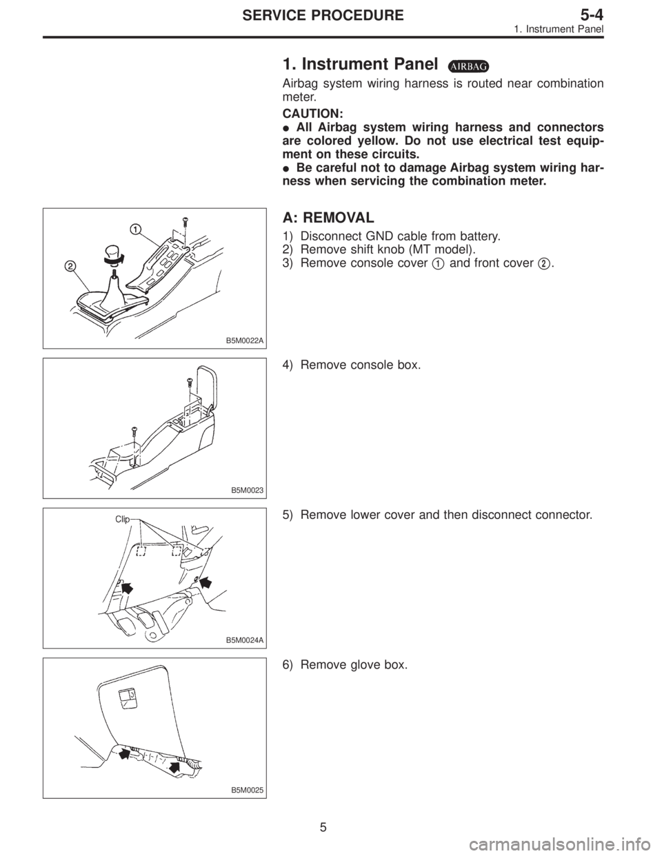
1) Disconnect GND cable from battery.
2) Remove shift knob (MT model).
3) Remove console cover�
1and front cover�2.
B5M0023
4) Remove console box.
B5M0024A
5) Remove lower cover and then disconnect connector.
B5M0025
6) Remove glove box.
5
5-4SERVICE PROCEDURE
1. Instrument Panel
Page 1567 of 2890
B5M0026
7) Remove cover back panel.
G5M0278
8) Remove two bolts and lower steering column.
B5M0027
9) Set temperature control lever to Max. COLD position,
and then disconnect temperature control cable from link of
heater module.
NOTE:
Do not move lever and link when installing.
B5M0028
10) Remove bolt cover and bolt of both side.
B5M0029A
11) Remove front side sill cover RH and then disconnect
airbag connector (AB9) and (AB10) (Airbag model).
to 5-5 [M2-6].>
6
5-4SERVICE PROCEDURE
1. Instrument Panel
Page 1568 of 2890
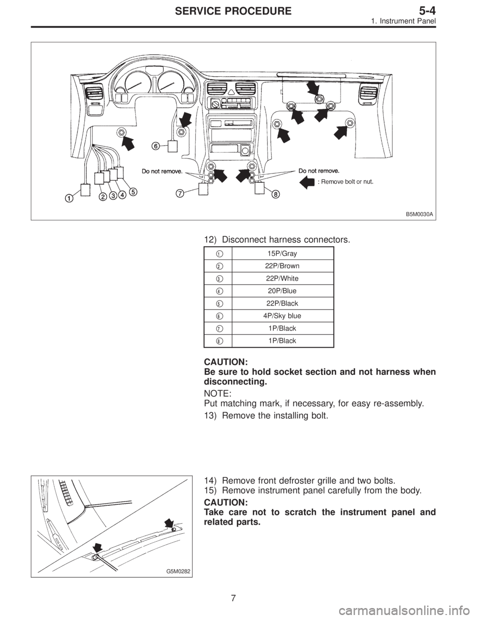
B5M0030A
12) Disconnect harness connectors.
�115P/Gray
�
222P/Brown
�
322P/White
�
420P/Blue
�
522P/Black
�
64P/Sky blue
�
71P/Black
�
81P/Black
CAUTION:
Be sure to hold socket section and not harness when
disconnecting.
NOTE:
Put matching mark, if necessary, for easy re-assembly.
13) Remove the installing bolt.
G5M0282
14) Remove front defroster grille and two bolts.
15) Remove instrument panel carefully from the body.
CAUTION:
Take care not to scratch the instrument panel and
related parts.
7
5-4SERVICE PROCEDURE
1. Instrument Panel
Page 1569 of 2890
G5M0602
CAUTION:
When storing removed instrument panel with passen-
ger airbag module, place it standing up on the floor.
B5M0031A
B: INSTALLATION
1) Installation is in the reverse order of removal.
Do the following:
When setting instrument panel into position, push two pins
into grommet on body panel.
CAUTION:
�Be careful not to snag the harness.
�Make sure to connect harness connectors.
�Take care not to scratch the instrument panel and
related parts.
B5M0032
2) Set clips located at both inside ends of instrument panel
onto body side.
8
5-4SERVICE PROCEDURE
1. Instrument Panel
Page 1581 of 2890
A: REMOVAL
1. DRIVER SIDE
1) Set front wheels in straight ahead position.
2) Turn ignition switch off.
3) Disconnect ground cable from battery and wait for at
least 20 seconds before starting work.
H5M0662A
4) Using TORX®BIT T30, remove two TORX®bolts.
H5M0664
5) Disconnect airbag connector on back of airbag module.
6) Refer to“CAUTION”for handling of a removed airbag
module.
2. PASSENGER SIDE
1) Remove instrument panel.
12
5-5SERVICE PROCEDURE
3. Airbag Module
Page 1605 of 2890
A: REMOVAL
1. DRIVER SIDE
1) Set front wheels in straight ahead position.
2) Turn ignition switch off.
3) Disconnect ground cable from battery and wait for at
least 20 seconds before starting work.
H5M0662A
4) Using TORX®BIT T30, remove two TORX®bolts.
H5M0664
5) Disconnect airbag connector on back of airbag module.
6) Refer to“CAUTION”for handling of a removed airbag
module.
2. PASSENGER SIDE
1) Remove instrument panel.
12
5-5bSERVICE PROCEDURE
3. Airbag Module
 Remove cover back panel.
G5M0278
8) Remove two bolts and lower steering column.
B5M0027
9) Set temperature control lever to Max. COLD position,
and then disconnect temperature control cable")
 Installation is in the reverse order of removal.
D")
 Set front wheels in straight ahead position.
2) Turn ignition switch off.
3) Disconnect ground cable from battery and wait for at
least 20 seconds before starting work.
H5")
 Set front wheels in straight ahead position.
2) Turn ignition switch off.
3) Disconnect ground cable from battery and wait for at
least 20 seconds before starting work.
H5")