Page 1661 of 2890
![SUBARU LEGACY 1996 Service Repair Manual CAUTION:
�Observe the items in 1. NORMAL CHARGING 6-2
[W2C1].
�Never use more than 10 amperes when charging the
battery because that will shorten battery life.
3. JUDGMENT OF BATTERY IN CHARGED
CONDIT](/manual-img/17/57433/w960_57433-1660.png "SUBARU LEGACY 1996 Service Repair Manual CAUTION:
�Observe the items in 1. NORMAL CHARGING 6-2
[W2C1].
�Never use more than 10 amperes when charging the
battery because that will shorten battery life.
3. JUDGMENT OF BATTERY IN CHARGED
CONDIT")
CAUTION:
�Observe the items in 1. NORMAL CHARGING 6-2
[W2C1].
�Never use more than 10 amperes when charging the
battery because that will shorten battery life.
3. JUDGMENT OF BATTERY IN CHARGED
CONDITION
1) Specific gravity of electrolyte is held at a specific value
in a range from 1.250 to 1.290 for more than one hour.
2) Voltage per battery cell is held at a specific value in a
range from 2.5 to 2.8 volts for more than one hour.
4. CHECK HYDROMETER FOR STATE OF CHARGE
Hydrometer indicator State of charge Required action
Green dot Above 65% Load test
Dark dot Below 65% Charge battery
Clear dot Low electrolyteReplace battery.* (If
cranking complaint)
*: Check electrical system before replacement.
B6M0236
3. Ignition Switch
A: REMOVAL AND INSTALLATION
1. IGNITION SWITCH
1) Remove screws, separate upper column cover and
lower column cover.
2) Remove instrument panel lower cover.
B6M0333
3) Disconnect ignition switch connector from body har-
ness.
4) Using a drift and hammer, hit the torn bolt head to
loosen and remove the ignition switch.
B6M0334A
5) When installing, tighten the connecting bolt until its
head twists off.
7
6-2SERVICE PROCEDURE
2. Battery - 3. Ignition Switch
Page 1662 of 2890
![SUBARU LEGACY 1996 Service Repair Manual CAUTION:
�Observe the items in 1. NORMAL CHARGING 6-2
[W2C1].
�Never use more than 10 amperes when charging the
battery because that will shorten battery life.
3. JUDGMENT OF BATTERY IN CHARGED
CONDIT](/manual-img/17/57433/w960_57433-1661.png "SUBARU LEGACY 1996 Service Repair Manual CAUTION:
�Observe the items in 1. NORMAL CHARGING 6-2
[W2C1].
�Never use more than 10 amperes when charging the
battery because that will shorten battery life.
3. JUDGMENT OF BATTERY IN CHARGED
CONDIT")
CAUTION:
�Observe the items in 1. NORMAL CHARGING 6-2
[W2C1].
�Never use more than 10 amperes when charging the
battery because that will shorten battery life.
3. JUDGMENT OF BATTERY IN CHARGED
CONDITION
1) Specific gravity of electrolyte is held at a specific value
in a range from 1.250 to 1.290 for more than one hour.
2) Voltage per battery cell is held at a specific value in a
range from 2.5 to 2.8 volts for more than one hour.
4. CHECK HYDROMETER FOR STATE OF CHARGE
Hydrometer indicator State of charge Required action
Green dot Above 65% Load test
Dark dot Below 65% Charge battery
Clear dot Low electrolyteReplace battery.* (If
cranking complaint)
*: Check electrical system before replacement.
B6M0236
3. Ignition Switch
A: REMOVAL AND INSTALLATION
1. IGNITION SWITCH
1) Remove screws, separate upper column cover and
lower column cover.
2) Remove instrument panel lower cover.
B6M0333
3) Disconnect ignition switch connector from body har-
ness.
4) Using a drift and hammer, hit the torn bolt head to
loosen and remove the ignition switch.
B6M0334A
5) When installing, tighten the connecting bolt until its
head twists off.
7
6-2SERVICE PROCEDURE
2. Battery - 3. Ignition Switch
Page 1663 of 2890

1) Remove instrument panel lower cover.
2) Remove lower column cover.
3) Unfasten holddown clip which secures harness, and
disconnect connector of ign")
B6M0048
B: INSPECTION
1. IGNITION SWITCH (ON-CAR)
1) Remove instrument panel lower cover.
2) Remove lower column cover.
3) Unfasten holddown clip which secures harness, and
disconnect connector of ignition switch from body harness.
4) Turn ignition key to each position and check continuity
between terminals of ignition switch connector.
Terminal
Positiona-1 a-2 a-5 a-4
LOCK
ACC��
ON���
START���
B6M0335A
4. Headlight
A: ADJUSTMENT
1. HEADLIGHT AIMING
1) Adjust the headlight aiming by turning the adjusting
screws.
CAUTION:
Before checking the headlight aiming, be sure of the
following:
�Turn off the light before adjusting headlight aiming.
If the light is necessary to check aiming, do not turn on
for more than two minutes.
�The area around the headlight has not sustained any
accident, damage or other type of deformation.
�Vehicle is parked on level ground.
�The inflation pressure of tires is correct.
�Vehicle’s gas tank is fully charged.
�Bounce the vehicle several times to normalize the
suspension.
�Make certain that someone is seated in the driver’s
seat.
NOTE:
Adjust vertical aim first, then horizontal aim.
8
6-2SERVICE PROCEDURE
3. Ignition Switch - 4. Headlight
Page 1664 of 2890

1) Remove instrument panel lower cover.
2) Remove lower column cover.
3) Unfasten holddown clip which secures harness, and
disconnect connector of ign")
B6M0048
B: INSPECTION
1. IGNITION SWITCH (ON-CAR)
1) Remove instrument panel lower cover.
2) Remove lower column cover.
3) Unfasten holddown clip which secures harness, and
disconnect connector of ignition switch from body harness.
4) Turn ignition key to each position and check continuity
between terminals of ignition switch connector.
Terminal
Positiona-1 a-2 a-5 a-4
LOCK
ACC��
ON���
START���
B6M0335A
4. Headlight
A: ADJUSTMENT
1. HEADLIGHT AIMING
1) Adjust the headlight aiming by turning the adjusting
screws.
CAUTION:
Before checking the headlight aiming, be sure of the
following:
�Turn off the light before adjusting headlight aiming.
If the light is necessary to check aiming, do not turn on
for more than two minutes.
�The area around the headlight has not sustained any
accident, damage or other type of deformation.
�Vehicle is parked on level ground.
�The inflation pressure of tires is correct.
�Vehicle’s gas tank is fully charged.
�Bounce the vehicle several times to normalize the
suspension.
�Make certain that someone is seated in the driver’s
seat.
NOTE:
Adjust vertical aim first, then horizontal aim.
8
6-2SERVICE PROCEDURE
3. Ignition Switch - 4. Headlight
Page 1667 of 2890
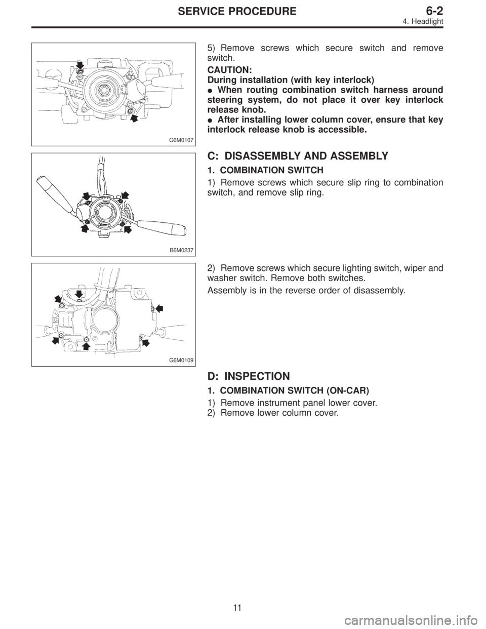
G6M0107
5) Remove screws which secure switch and remove
switch.
CAUTION:
During installation (with key interlock)
�When routing combination switch harness around
steering system, do not place it over key interlock
release knob.
�After installing lower column cover, ensure that key
interlock release knob is accessible.
B6M0237
C: DISASSEMBLY AND ASSEMBLY
1. COMBINATION SWITCH
1) Remove screws which secure slip ring to combination
switch, and remove slip ring.
G6M0109
2) Remove screws which secure lighting switch, wiper and
washer switch. Remove both switches.
Assembly is in the reverse order of disassembly.
D: INSPECTION
1. COMBINATION SWITCH (ON-CAR)
1) Remove instrument panel lower cover.
2) Remove lower column cover.
11
6-2SERVICE PROCEDURE
4. Headlight
Page 1674 of 2890
6. Turn Signal and Hazard Warning
Light
A: REMOVAL AND INSTALLATION
1. FRONT TURN SIGNAL LIGHT
Refer to 6-2 [W4B2] as for removal and installation of front
turn signal light.
NOTE:
The front turn signal light is united with headlight assem-
bly.
2. REAR COMBINATION LIGHT
Refer to 6-2 [W5A1] as for removal and installation of rear
combination light.
3. COMBINATION SWITCH
Refer to 6-2 [W4B3] as for removal and installation of com-
bination switch.
B6M0063
4. HAZARD SWITCH
1) Remove center panel from instrument panel.
5-4 [W1A0].>
2) Disconnect connector of hazard switch from body har-
ness.
3) Remove hazard switch from center panel.
B6M0343A
5. TURN SIGNAL AND HAZARD UNIT
1) Remove instrument panel lower cover.
2) Remove engine hood opener lever bracket.
3) Disconnect connector of turn signal and hazard unit.
4) Remove screw, and then remove turn signal and haz-
ard unit from bracket.
18
6-2SERVICE PROCEDURE
6. Turn Signal and Hazard Warning Light
Page 1675 of 2890
B: DISASSEMBLY AND ASSEMBLY
1. COMBINATION SWITCH
Refer to 6-2 [W4C1] as for disassembly and assembly of
combination switch.
C: INSPECTION
1. COMBINATION SWITCH (ON-CAR)
1) Remove instrument panel lower cover.
2) Remove lower column cover.
B6M0238
3) Unfasten holddown clip which secures harness, and
disconnect connectors from body harness.
4) Move combination switch to respective positions and
check continuity between terminals as indicated in table
below:
Turn signal switch
Terminal
Switch positiona-5 a-7 a-6
TurnL⋅L′��
*xx
N
*xx
R⋅R′��
B6M0344
2. HAZARD SWITCH
Move hazard switch to each position and check continuity
between terminals as indicated in table below:
73910561 2
ON��
�����
OFF����
19
6-2SERVICE PROCEDURE
6. Turn Signal and Hazard Warning Light
Page 1683 of 2890
6. COMBINATION SWITCH
Refer to 6-2 [W4B3] as for removal and installation of com-
bination switch.
C: DISASSEMBLY AND ASSEMBLY
1. COMBINATION SWITCH AND INTERMITTENT UNIT
Refer to 6-2 [W4C1] as for disassembly and assembly of
combination switch.
D: INSPECTION
1. COMBINATION SWITCH (ON-CAR)
1) Remove instrument panel lower cover.
2) Remove lower column cover.
25
6-2SERVICE PROCEDURE
10. Front Wiper and Washer
![SUBARU LEGACY 1996 Service Repair Manual 6. Turn Signal and Hazard Warning
Light
A: REMOVAL AND INSTALLATION
1. FRONT TURN SIGNAL LIGHT
Refer to 6-2 [W4B2] as for removal and installation of front
turn signal light.
NOTE:
The front turn sign](/manual-img/17/57433/w960_57433-1673.png "SUBARU LEGACY 1996 Service Repair Manual 6. Turn Signal and Hazard Warning
Light
A: REMOVAL AND INSTALLATION
1. FRONT TURN SIGNAL LIGHT
Refer to 6-2 [W4B2] as for removal and installation of front
turn signal light.
NOTE:
The front turn sign")
![SUBARU LEGACY 1996 Service Repair Manual B: DISASSEMBLY AND ASSEMBLY
1. COMBINATION SWITCH
Refer to 6-2 [W4C1] as for disassembly and assembly of
combination switch.
C: INSPECTION
1. COMBINATION SWITCH (ON-CAR)
1) Remove instrument panel low](/manual-img/17/57433/w960_57433-1674.png "SUBARU LEGACY 1996 Service Repair Manual B: DISASSEMBLY AND ASSEMBLY
1. COMBINATION SWITCH
Refer to 6-2 [W4C1] as for disassembly and assembly of
combination switch.
C: INSPECTION
1. COMBINATION SWITCH (ON-CAR)
1) Remove instrument panel low")
![SUBARU LEGACY 1996 Service Repair Manual 6. COMBINATION SWITCH
Refer to 6-2 [W4B3] as for removal and installation of com-
bination switch.
C: DISASSEMBLY AND ASSEMBLY
1. COMBINATION SWITCH AND INTERMITTENT UNIT
Refer to 6-2 [W4C1] as for di](/manual-img/17/57433/w960_57433-1682.png "SUBARU LEGACY 1996 Service Repair Manual 6. COMBINATION SWITCH
Refer to 6-2 [W4B3] as for removal and installation of com-
bination switch.
C: DISASSEMBLY AND ASSEMBLY
1. COMBINATION SWITCH AND INTERMITTENT UNIT
Refer to 6-2 [W4C1] as for di")