Page 1829 of 2890
 Turn ignition switch to ON (engine OFF) and Subaru
select monitor switch to ON.
7) Start the engine.
NOTE:
�Ensure the selector lever is placed in the“P”position
before starting. (AT ve")
OBD0060
6) Turn ignition switch to ON (engine OFF) and Subaru
select monitor switch to ON.
7) Start the engine.
NOTE:
�Ensure the selector lever is placed in the“P”position
before starting. (AT vehicles)
�Depress clutch pedal when starting the engine. (MT
vehicles)
8) Using the selector lever or shift lever, turn the“P”posi-
tion switch and the“N”position switch to ON.
9) Depress the brake pedal to turn the brake switch ON.
(AT vehicles)
10) Keep engine speed in the 2,500—3,000 rpm range
for 40 seconds.
NOTE:
On models without tachometer, use the Subaru select
monitor or tachometer (Secondary pickup type).
11) Place the selector lever or shift lever in the“D”posi-
tion (AT vehicles) or“1st”gear (MT vehicles) and drive the
vehicle at 5 to 10 km/h (3 to 6 MPH).
NOTE:
�On AWD vehicles, release the parking brake.
�The speed difference between front and rear wheels
may light either the ABS or the ABS/TCS warning light, but
this indicates no malfunctions. When engine control diag-
nosis is finished, perform the ABS or the ABS/TCS memory
clearance procedure of self-diagnosis system.
4-4b [T6D2] or [T9K0], 4-4c [T6D2] or [T9J0].>
OBD0005B
3. OBD-II GENERAL SCAN TOOL
After performing diagnostics and clearing the memory,
check for any remaining unresolved trouble data:
1) Connect test mode connector at the lower side of the
instrument panel (on the driver’s side), to the side of the
center console box.
OBD0006C
2) Open the cover and connect the OBD-II general scan
tool to its data link connector in the lower portion of the
instrument panel (on the driver’s side), to the lower cover.
CAUTION:
Do not connect the scan tools except for Subaru select
monitor and OBD-II general scan tool.
61
2-7ON-BOARD DIAGNOSTICS II SYSTEM
3. Diagnosis System
Page 1832 of 2890
 Insert cartridge into Subaru select monitor.
OBD0005B
4) Connect test mode connector at the lower portion of
instrument panel (on the driver’s side), to the side of the
center console box")
G3M0150
3) Insert cartridge into Subaru select monitor.
OBD0005B
4) Connect test mode connector at the lower portion of
instrument panel (on the driver’s side), to the side of the
center console box.
OBD0059A
5) Connect Subaru select monitor to data link connector.
�Using data link connector for Subaru select monitor only:
Connect Subaru select monitor to its data link connector
located in the lower portion of the instrument panel (on the
driver’s side), to the side of the center console box.
OBD0669A
�Using data link connector for Subaru select monitor and
OBD-II general scan tool:
(1) Connect ST to Subaru select monitor cable.
ST1 498357200 ADAPTER CABLE
OBD0006C
(2) Open the cover and connect Subaru select monitor
to data link connector located in the lower portion of the
instrument panel (on the driver’s side), to the lower
cover.
CAUTION:
Do not connect scan tools except for Subaru select
monitor and OBD-II general scan tool.
64
2-7ON-BOARD DIAGNOSTICS II SYSTEM
3. Diagnosis System
Page 1834 of 2890
B2M0652
NOTE:
When in compulsory valve operation check mode the moni-
tor indicates the execution of valve check on display.
B2M0653
(2) When not executing or stopping the compulsory
valve check mode, press the function key [1].
B2M0643
11) When compulsory valve operation check mode is
exited or check completed, the monitor indicates the
completion of compulsory valve operation check on the
display, and automatically returns to the initial mode
(FUNCTION MODE: F00).
G3M0151
G: FINISHING DIAGNOSIS OPERATION
1. SUBARU SELECT MONITOR
1) Disconnect test mode connector at the lower portion of
instrument panel (on the driver’s side), to the side of the
center console box.
2) Turn Subaru select monitor switch and ignition switch to
OFF.
3) Disconnect Subaru select monitor from its data link con-
nector.
66
2-7ON-BOARD DIAGNOSTICS II SYSTEM
3. Diagnosis System
Page 1836 of 2890
 Use engine grounding terminal or engine proper as the
grounding point to the body when measuring voltage and
resistance in the engine compartment.
8) Every MFI-related part is a precision")
B2M0648A
7) Use engine grounding terminal or engine proper as the
grounding point to the body when measuring voltage and
resistance in the engine compartment.
8) Every MFI-related part is a precision part. Do not drop
them.
9) Observe the following cautions when installing a radio
in MFI equipped models.
CAUTION:
�The antenna must be kept as far apart as possible
from the control unit.
(The ECM is located under the steering column, inside
of the instrument panel lower trim panel.)
�The antenna feeder must be placed as far apart as
possible from the ECM and MFI harness.
�Carefully adjust the antenna for correct matching.
�When mounting a large power type radio, pay spe-
cial attention to the three items above mentioned.
�Incorrect installation of the radio may affect the
operation of the ECM.
10) Before disconnecting the fuel hose, disconnect the
fuel pump connector and crank the engine for more than
five seconds to release pressure in the fuel system. If
engine starts during this operation, run it until it stops.
11) Problems in the electronic-controlled automatic trans-
mission may be caused by failure of the engine, the elec-
tronic control system, the transmission proper, or by a com-
bination of these. These three causes must be distin-
guished clearly when performing diagnostics.
12) Diagnostics should be conducted by rotating with
simple, easy operations and proceeding to complicated,
difficult operations. The most important thing in diagnostics
is to understand the customer’s complaint, and distinguish
between the three causes.
13) In AT vehicles, do not continue the stall for more than
five seconds at a time (from closed throttle, fully open
throttle to stall engine speed).
14) On ABS or ABS/TCS vehicle, when performing driving
test in jacked-up or lifted-up position, sometimes the warn-
ing light may be lit, but this is not a malfunction of the sys-
tem. The reason for this is the speed difference between
the front and rear wheels. After diagnosis of engine control
system, perform the ABS or ABS/TCS memory clearance
procedure of self-diagnosis system.
[T9K0], 4-4c [T6D2] or [T9J0].>
68
2-7ON-BOARD DIAGNOSTICS II SYSTEM
4. Cautions
Page 2011 of 2890
 Turn ignition switch to OFF.
2) Connect test mode connector at the lower portion of
instrument panel (on the driver’s side), to the sid")
OBD0005B
10AH2CHECK PURGE CONTROL SOLENOID
VALVE OPERATION.
1) Turn ignition switch to OFF.
2) Connect test mode connector at the lower portion of
instrument panel (on the driver’s side), to the side of the
center console box.
3) Turn ignition switch to ON.
: Does purge control solenoid valve produce
operating sound at about 0.3 Hz?
NOTE:
Purge control solenoid valve operation check can also be
executed using Subaru Select Monitor (Function mode:
FD02). For the procedure, refer to“COMPULSORY VALVE
OPERATION CHECK MODE”2-7 [T3F0].
: Go to next step 4).
: Replace purge control solenoid valve.
4) Disconnect canister purge hose from canister.
: Does pulsation occur by blowing through
the canister purge hose?
: Repair or replace evaporation line.
NOTE:
In this case, repair the following:
�Loose connections in evaporation line
�Cracks in evaporation line
�Clogging in evaporation line
: Replace purge control solenoid valve.
243
2-7ON-BOARD DIAGNOSTICS II SYSTEM
10. Diagnostics Chart with Trouble Code
Page 2109 of 2890
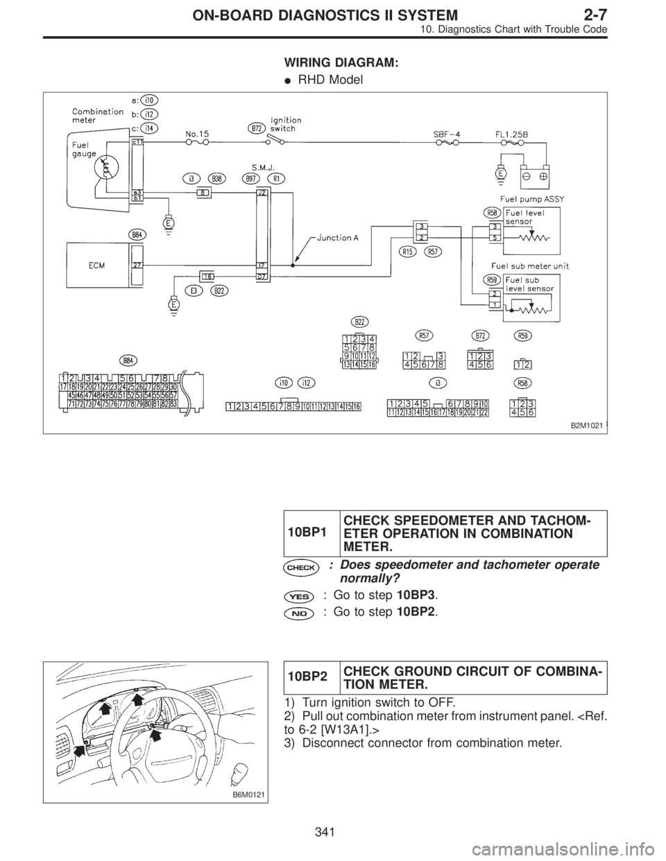
WIRING DIAGRAM:
�RHD Model
B2M1021
10BP1CHECK SPEEDOMETER AND TACHOM-
ETER OPERATION IN COMBINATION
METER.
: Does speedometer and tachometer operate
normally?
: Go to step10BP3.
: Go to step10BP2.
B6M0121
10BP2CHECK GROUND CIRCUIT OF COMBINA-
TION METER.
1) Turn ignition switch to OFF.
2) Pull out combination meter from instrument panel.
to 6-2 [W13A1].>
3) Disconnect connector from combination meter.
341
2-7ON-BOARD DIAGNOSTICS II SYSTEM
10. Diagnostics Chart with Trouble Code
Page 2116 of 2890
 Separate bulkhead wiring harness connector (B38)
and instrument panel wiring harness connector (i3).
15) Measure resistance of harness between bulkhead wir-
ing harness connector and chas")
B2M0944A
14) Separate bulkhead wiring harness connector (B38)
and instrument panel wiring harness connector (i3).
15) Measure resistance of harness between bulkhead wir-
ing harness connector and chassis ground.
: Connector & terminal
(B99) No. 20—Chassis ground:
Is the resistance less than 10Ω?
: Repair short circuit in bulkhead wiring harness.
: Repair short circuit in instrument panel wiring har-
ness.
G2M0340
10BP10CHECK HARNESS BETWEEN ECM, COM-
BINATION METER AND FUEL PUMP
CONNECTOR. (RHD MODEL)
1) Turn ignition switch to OFF.
2) Remove fuel pump access hole lid located on the right
rear of luggage compartment floor.
B2M0940A
3) Disconnect connector from fuel pump.
4) Measure resistance of harness between fuel pump con-
nector and chassis ground.
: Connector & terminal
(R58) No. 3—Chassis ground:
Is the resistance less than 10Ω?
: Go to next step 5).
: Go to step10BP11.
G2M0863
5) Remove service hole cover located on the left rear of
luggage compartment floor.
B2M0940A
6) Disconnect connector from fuel sub meter unit.
7) Measure resistance of harness between fuel pump con-
nector and chassis ground.
: Connector & terminal
(R58) No. 3—Chassis ground:
Is the resistance less than 10Ω?
: Repair short circuit in harness between fuel pump
and fuel sub meter unit connector.
: Go to next step 8).
348
2-7ON-BOARD DIAGNOSTICS II SYSTEM
10. Diagnostics Chart with Trouble Code
Page 2117 of 2890
 Separate fuel tank cord connector (R57) and rear wir-
ing harness connector (R15).
9) Measure resistance of harness between fuel sub meter
unit connector and chassis ground.
: Connector &")
B2M0941A
8) Separate fuel tank cord connector (R57) and rear wir-
ing harness connector (R15).
9) Measure resistance of harness between fuel sub meter
unit connector and chassis ground.
: Connector & terminal
(R59) No. 1—Chassis ground:
Is the resistance less than 10Ω?
: Repair short circuit in fuel tank cord.
: Go to next step 10).
B2M0942A
10) Separate rear wiring harness connector (R1) and bulk-
head wiring harness connector (B97).
11) Measure resistance of harness between rear wiring
harness connector and chassis ground.
: Connector & terminal
(R15) No. 3—Chassis ground:
Is the resistance less than 10Ω?
: Go to next step 12).
: Repair short circuit in rear wiring harness.
B2M1022A
12) Measure resistance of harness between bulkhead wir-
ing connector and chassis ground.
: Connector & terminal
(B97) No. J2—Chassis ground:
Is the resistance less than 10Ω?
: Go to next step 13).
: Repair short circuit in harness between S.M.J.
and ECM connector.
B2M1022A
13) Separate bulkhead wiring harness connector (B38)
and instrument panel wiring harness connector (i3).
14) Measure resistance of harness between bulkhead wir-
ing harness connector and chassis ground.
: Connector & terminal
(B97) No. J2—Chassis ground:
Is the resistance less than 10Ω?
: Repair short circuit in bulkhead wiring harness.
: Repair short circuit in instrument panel wiring har-
ness.
349
2-7ON-BOARD DIAGNOSTICS II SYSTEM
10. Diagnostics Chart with Trouble Code
 When not executing or stopping the compulsory
valve check mode,")