Page 1688 of 2890
4. WASHER TANK AND WASHER MOTOR
Refer to 6-2 [W10B4] as for removal and installation of
washer tank and washer motor.
5. COMBINATION SWITCH
Refer to 6-2 [W4B3] as for removal and installation of com-
bination switch.
C: DISASSEMBLY AND ASSEMBLY
1. COMBINATION SWITCH
Refer to 6-2 [W4C1] as for disassembly and assembly of
combination switch.
D: INSPECTION
1. COMBINATION SWITCH (ON-CAR)
1) Remove instrument panel lower cover.
2) Remove lower column cover.
29
6-2SERVICE PROCEDURE
11. Rear Wiper and Washer
Page 1690 of 2890
G6M0134
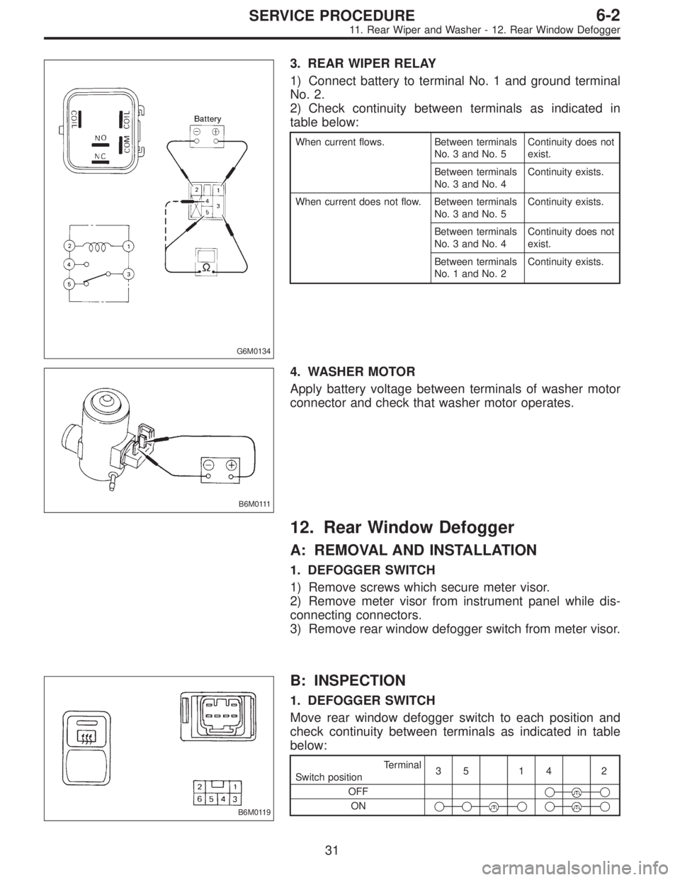
3. REAR WIPER RELAY
1) Connect battery to terminal No. 1 and ground terminal
No. 2.
2) Check continuity between terminals as indicated in
table below:
When current flows. Between terminals
No. 3 and No. 5Continuity does not
exist.
Between terminals
No. 3 and No. 4Continuity exists.
When current does not flow. Between terminals
No. 3 and No. 5Continuity exists.
Between terminals
No. 3 and No. 4Continuity does not
exist.
Between terminals
No. 1 and No. 2Continuity exists.
B6M0111
4. WASHER MOTOR
Apply battery voltage between terminals of washer motor
connector and check that washer motor operates.
12. Rear Window Defogger
A: REMOVAL AND INSTALLATION
1. DEFOGGER SWITCH
1) Remove screws which secure meter visor.
2) Remove meter visor from instrument panel while dis-
connecting connectors.
3) Remove rear window defogger switch from meter visor.
B6M0119
B: INSPECTION
1. DEFOGGER SWITCH
Move rear window defogger switch to each position and
check continuity between terminals as indicated in table
below:
Terminal
Switch position35 14 2
OFF�
�
ON�����
31
6-2SERVICE PROCEDURE
11. Rear Wiper and Washer - 12. Rear Window Defogger
Page 1691 of 2890
G6M0134
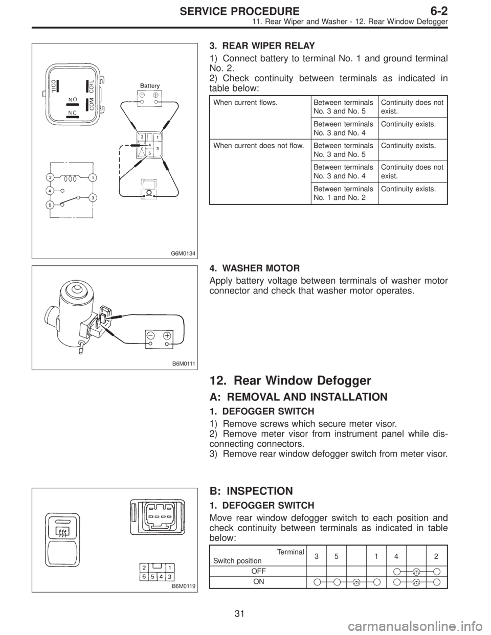
3. REAR WIPER RELAY
1) Connect battery to terminal No. 1 and ground terminal
No. 2.
2) Check continuity between terminals as indicated in
table below:
When current flows. Between terminals
No. 3 and No. 5Continuity does not
exist.
Between terminals
No. 3 and No. 4Continuity exists.
When current does not flow. Between terminals
No. 3 and No. 5Continuity exists.
Between terminals
No. 3 and No. 4Continuity does not
exist.
Between terminals
No. 1 and No. 2Continuity exists.
B6M0111
4. WASHER MOTOR
Apply battery voltage between terminals of washer motor
connector and check that washer motor operates.
12. Rear Window Defogger
A: REMOVAL AND INSTALLATION
1. DEFOGGER SWITCH
1) Remove screws which secure meter visor.
2) Remove meter visor from instrument panel while dis-
connecting connectors.
3) Remove rear window defogger switch from meter visor.
B6M0119
B: INSPECTION
1. DEFOGGER SWITCH
Move rear window defogger switch to each position and
check continuity between terminals as indicated in table
below:
Terminal
Switch position35 14 2
OFF�
�
ON�����
31
6-2SERVICE PROCEDURE
11. Rear Wiper and Washer - 12. Rear Window Defogger
Page 1693 of 2890
G6M0137
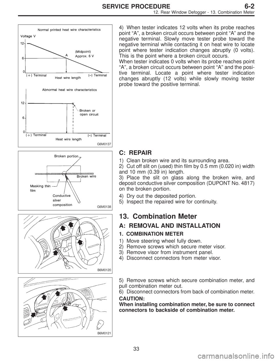
4) When tester indicates 12 volts when its probe reaches
point“A”, a broken circuit occurs between point“A”and the
negative terminal. Slowly move tester probe toward the
negative terminal while contacting it on heat wire to locate
point where tester indication changes abruptly (0 volts).
This is the point where a broken circuit occurs.
When tester indicates 0 volts when its probe reaches point
“A”, a broken circuit occurs between point“A”and the posi-
tive terminal. Locate a point where tester indication
changes abruptly (12 volts) while slowly moving tester
probe toward the positive terminal.
G6M0138
C: REPAIR
1) Clean broken wire and its surrounding area.
2) Cut off slit on (used) thin film by 0.5 mm (0.020 in) width
and 10 mm (0.39 in) length.
3) Place the slit on glass along the broken wire, and
deposit conductive silver composition (DUPONT No. 4817)
on the broken portion.
4) Dry out the deposited portion.
5) Inspect the repaired wire for continuity.
B6M0120
13. Combination Meter
A: REMOVAL AND INSTALLATION
1. COMBINATION METER
1) Move steering wheel fully down.
2) Remove screws which secure meter visor.
3) Remove visor from instrument panel.
4) Disconnect connectors from meter visor.
B6M0121
5) Remove screws which secure combination meter, and
pull combination meter out.
6) Disconnect connectors from back of combination meter.
CAUTION:
When installing combination meter, be sure to connect
connectors to backside of combination meter.
33
6-2SERVICE PROCEDURE
12. Rear Window Defogger - 13. Combination Meter
Page 1694 of 2890
G6M0137
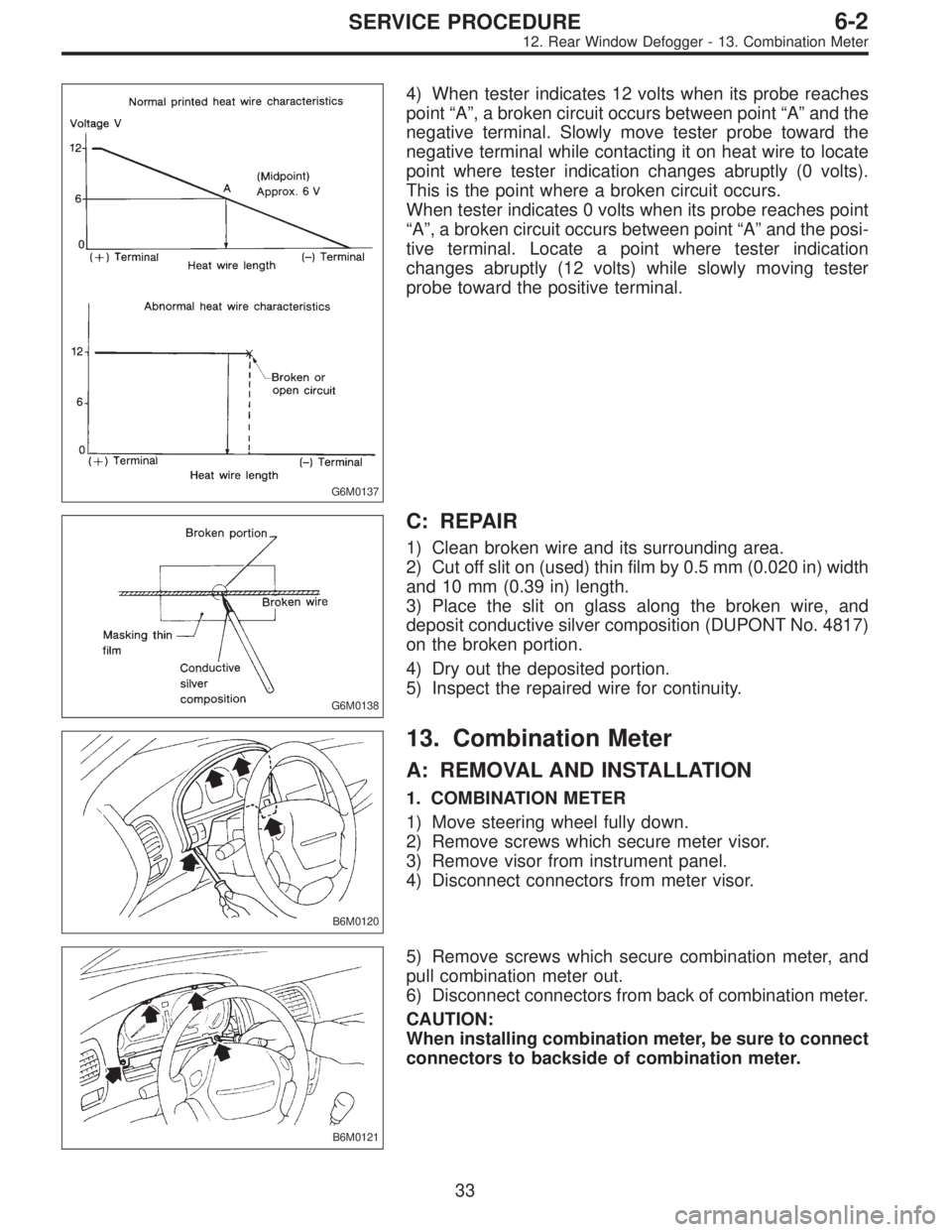
4) When tester indicates 12 volts when its probe reaches
point“A”, a broken circuit occurs between point“A”and the
negative terminal. Slowly move tester probe toward the
negative terminal while contacting it on heat wire to locate
point where tester indication changes abruptly (0 volts).
This is the point where a broken circuit occurs.
When tester indicates 0 volts when its probe reaches point
“A”, a broken circuit occurs between point“A”and the posi-
tive terminal. Locate a point where tester indication
changes abruptly (12 volts) while slowly moving tester
probe toward the positive terminal.
G6M0138
C: REPAIR
1) Clean broken wire and its surrounding area.
2) Cut off slit on (used) thin film by 0.5 mm (0.020 in) width
and 10 mm (0.39 in) length.
3) Place the slit on glass along the broken wire, and
deposit conductive silver composition (DUPONT No. 4817)
on the broken portion.
4) Dry out the deposited portion.
5) Inspect the repaired wire for continuity.
B6M0120
13. Combination Meter
A: REMOVAL AND INSTALLATION
1. COMBINATION METER
1) Move steering wheel fully down.
2) Remove screws which secure meter visor.
3) Remove visor from instrument panel.
4) Disconnect connectors from meter visor.
B6M0121
5) Remove screws which secure combination meter, and
pull combination meter out.
6) Disconnect connectors from back of combination meter.
CAUTION:
When installing combination meter, be sure to connect
connectors to backside of combination meter.
33
6-2SERVICE PROCEDURE
12. Rear Window Defogger - 13. Combination Meter
Page 1698 of 2890
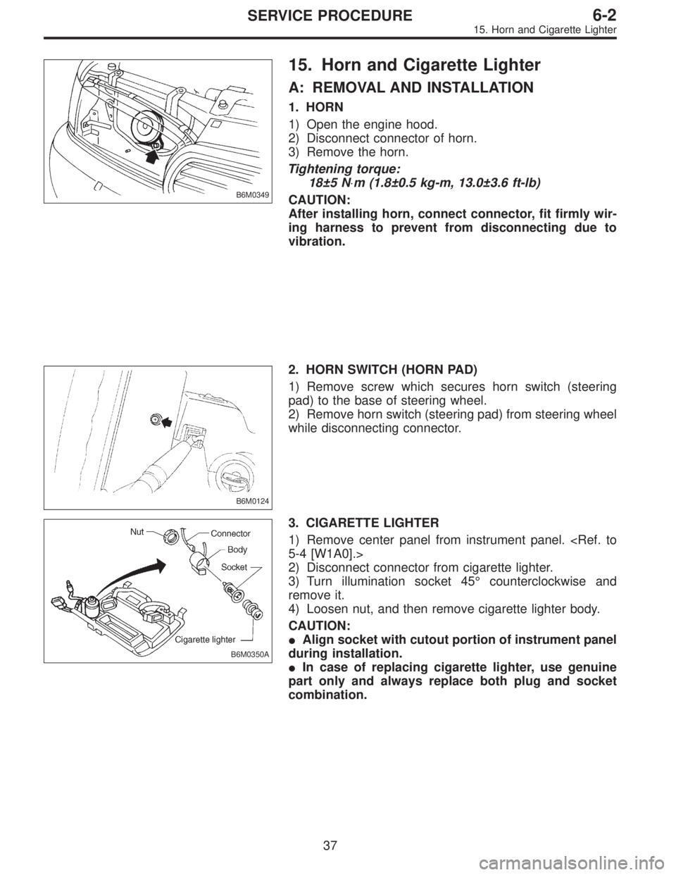
B6M0349
15. Horn and Cigarette Lighter
A: REMOVAL AND INSTALLATION
1. HORN
1) Open the engine hood.
2) Disconnect connector of horn.
3) Remove the horn.
Tightening torque:
18±5 N⋅m (1.8±0.5 kg-m, 13.0±3.6 ft-lb)
CAUTION:
After installing horn, connect connector, fit firmly wir-
ing harness to prevent from disconnecting due to
vibration.
B6M0124
2. HORN SWITCH (HORN PAD)
1) Remove screw which secures horn switch (steering
pad) to the base of steering wheel.
2) Remove horn switch (steering pad) from steering wheel
while disconnecting connector.
B6M0350A
3. CIGARETTE LIGHTER
1) Remove center panel from instrument panel.
5-4 [W1A0].>
2) Disconnect connector from cigarette lighter.
3) Turn illumination socket 45°counterclockwise and
remove it.
4) Loosen nut, and then remove cigarette lighter body.
CAUTION:
�Align socket with cutout portion of instrument panel
during installation.
�In case of replacing cigarette lighter, use genuine
part only and always replace both plug and socket
combination.
37
6-2SERVICE PROCEDURE
15. Horn and Cigarette Lighter
Page 1704 of 2890
![SUBARU LEGACY 1996 Service Repair Manual B6M0133
B: INSPECTION
1. DOOR LOCK SWITCH (DRIVER’S DOOR)
1) Remove door trim panel. <Ref. to 5-2 [W2A2].>
2) Disconnect connector of door switch.
3) Set switch to each position and check continuity SUBARU LEGACY 1996 Service Repair Manual B6M0133
B: INSPECTION
1. DOOR LOCK SWITCH (DRIVER’S DOOR)
1) Remove door trim panel. <Ref. to 5-2 [W2A2].>
2) Disconnect connector of door switch.
3) Set switch to each position and check continuity](/manual-img/17/57433/w960_57433-1703.png)
B6M0133
B: INSPECTION
1. DOOR LOCK SWITCH (DRIVER’S DOOR)
1) Remove door trim panel.
2) Disconnect connector of door switch.
3) Set switch to each position and check continuity
between terminals as indicated in table below:
Terminal
Switch position12
UNLOCK��
LOCK
B6M0135
2. ACTUATOR
1) Remove door trim panel.
2) Disconnect connector of actuator.
3) Make sure that door link moves to LOCK or UNLOCK
position when battery voltage is applied between terminals
as described below:
�Connect battery positive (+) terminal to terminal No. 2,
and negative (�) terminal to terminal No. 4 at a moment.
�Connect battery positive (+) terminal to terminal No. 4,
and negative terminal (�) to terminal No. 2 at a moment.
B6M0352A
18. Remote Controlled Rearview Mirror
A: REMOVAL AND INSTALLATION
1. REMOTE CONTROLLED REARVIEW MIRROR
SWITCH
1) Remove rearview mirror switch from instrument panel
by using a small standard screwdriver.
CAUTION:
Do not pry rearview mirror switch forcefully as this
may scratch instrument panel.
2) Remove rearview mirror switch while disconnecting
connector.
42
6-2SERVICE PROCEDURE
17. Power Door Lock - 18. Remote Controlled Rearview Mirror
Page 1705 of 2890
![SUBARU LEGACY 1996 Service Repair Manual B6M0133
B: INSPECTION
1. DOOR LOCK SWITCH (DRIVER’S DOOR)
1) Remove door trim panel. <Ref. to 5-2 [W2A2].>
2) Disconnect connector of door switch.
3) Set switch to each position and check continuity SUBARU LEGACY 1996 Service Repair Manual B6M0133
B: INSPECTION
1. DOOR LOCK SWITCH (DRIVER’S DOOR)
1) Remove door trim panel. <Ref. to 5-2 [W2A2].>
2) Disconnect connector of door switch.
3) Set switch to each position and check continuity](/manual-img/17/57433/w960_57433-1704.png)
B6M0133
B: INSPECTION
1. DOOR LOCK SWITCH (DRIVER’S DOOR)
1) Remove door trim panel.
2) Disconnect connector of door switch.
3) Set switch to each position and check continuity
between terminals as indicated in table below:
Terminal
Switch position12
UNLOCK��
LOCK
B6M0135
2. ACTUATOR
1) Remove door trim panel.
2) Disconnect connector of actuator.
3) Make sure that door link moves to LOCK or UNLOCK
position when battery voltage is applied between terminals
as described below:
�Connect battery positive (+) terminal to terminal No. 2,
and negative (�) terminal to terminal No. 4 at a moment.
�Connect battery positive (+) terminal to terminal No. 4,
and negative terminal (�) to terminal No. 2 at a moment.
B6M0352A
18. Remote Controlled Rearview Mirror
A: REMOVAL AND INSTALLATION
1. REMOTE CONTROLLED REARVIEW MIRROR
SWITCH
1) Remove rearview mirror switch from instrument panel
by using a small standard screwdriver.
CAUTION:
Do not pry rearview mirror switch forcefully as this
may scratch instrument panel.
2) Remove rearview mirror switch while disconnecting
connector.
42
6-2SERVICE PROCEDURE
17. Power Door Lock - 18. Remote Controlled Rearview Mirror