Page 257 of 2890
ON-BOARD
DIAGNOSTICS
II
SYSTEM
[TloBw2i
2-7
10
.
Diagnostics
Chart
with
Trouble
Code
WIRING
DIAGRAM
:
a
:
QD
Combination
b
:
i12
meter
Ignition
c
:
i14
No
.
15W2
switch
SBF-4
FL1
.25B
Fuel
gauge
S
.M
.J
.
O
O
E
E)
El)
Fuel
pumpASSY
R58
Fuel
level
sensor
Junction
A
R15R57
ECM
~
Fuel
sub
meter
unit
Fuel
sub
O
~p
level
sensor
E
822
R57
872
R59
1
5
1
6
1
7
1
8
'
,
O
,'
IyWJJ
LJJJ
LJJ
u
4u
1Ju
i10
i~2
117118119~2
.0121122123V4
.
.
.
.
.
.
(D
1
1
1
141
141EIb1
B2M1021
CHECK
SPEEDOMETER
AND
TACHOMETER
(OPERATION
IN
COMBINATION
METER
.
CHECK
:
Does
speedometer
and
tachometer
operate
normally?
vES
:
Go
to
step
10BW3
.
No
:
Go
to
step
10BW2
.
10BW2
I
CHECK
GROUND
CIRCUIT
OFCOMBINA-
TION
METER
.
1)
Turn
ignition
switch
to
OFF
.
2)
Pull
out
combination
meter
from
instrument
panel
.
<
Ref
.
to
6-2
[W13A1
]
.*1
>
3)
Disconnect
connector
from
combination
meter
.
47
Page 263 of 2890
![SUBARU LEGACY 1996 Service Repair Manual
ON-BOARD
DIAGNOSTICS
II
SYSTEM
[TIoBw9]
2-7
10
.
DiagnosticsChart
with
Trouble
Code
R58
B2M0940A
I
R59
82M0941A
I
R15
B2M0942A
I
6)
Disconnect
connector
from
fuel
sub
meter
unit
.
7)
Measure](/manual-img/17/57433/w960_57433-262.png "SUBARU LEGACY 1996 Service Repair Manual
ON-BOARD
DIAGNOSTICS
II
SYSTEM
[TIoBw9]
2-7
10
.
DiagnosticsChart
with
Trouble
Code
R58
B2M0940A
I
R59
82M0941A
I
R15
B2M0942A
I
6)
Disconnect
connector
from
fuel
sub
meter
unit
.
7)
Measure")
ON-BOARD
DIAGNOSTICS
II
SYSTEM
[TIoBw9]
2-7
10
.
DiagnosticsChart
with
Trouble
Code
R58
B2M0940A
I
R59
82M0941A
I
R15
B2M0942A
I
6)
Disconnect
connector
from
fuel
sub
meter
unit
.
7)
Measure
resistance
of
harness
between
fuel
pump
connector
and
chassis
ground
.
CHECK
:
Connector
&
terminal
(R58)
No
.
3
-
Chassis
ground
:
Is
the
resistance
less
than
10
92?
YES
:
Repair
short
circuit
in
harness
between
fuel
pump
and
fuel
sub
meter
unit
connector
.
No
:
Go
to
nextstep
8)
.
8)
Separate
fuel
tank
cord
connector
(R57)
and
rear
wir-
ing
harness
connector
(R15)
.
9)
Measure
resistance
of
harness
between
fuel
sub
meter
unit
connector
and
chassis
ground
.
CHECK
:
Connector
&
terminal
(R59)
No
.
1
-
Chassis
ground
:
Is
the
resistance
less
than10
S2?
,rES
:
Repair
short
circuit
in
fuel
tankcord
.
No
:
Go
to
nextstep
10)
.
10)
Separate
rear
wiring
harness
connector
(R1)
and
bulkhead
wiring
harness
connector
(B97)
.
11)
Measure
resistance
of
harness
between
rear
wiring
harnessconnector
and
chassis
ground
.
CHECK
:
Connector
&
terminal
(R15)
No
.
3
-
Chassis
ground
:
Is
the
resistance
less
than10
0?
,rES
:
Repair
short
circuit
in
rear
wiring
harness
.
No
:
Go
to
nextstep
12)
.
12)
Measure
resistance
of
harness
between
bulkhead
wir-
ing
connector
and
chassis
ground
.
CHECK
:
Connector
&
terminal
(B97)
No
.
J2
-
Chassis
ground
:
Is
the
resistance
less
than10
S2?
,rES
:
Go
to
nextstep
13)
.
No
:
Repair
short
circuit
and
ECM
connector
.
in
harness
between
S
.M
.J
.
13)
Separate
bulkhead
wiring
harness
connector
(B38)
and
instrument
panel
wiring
harness
connector
(i3)
.
14)
Measure
resistance
of
harness
between
bulkhead
wir-
ing
harness
connector
and
chassis
ground
.
CHECK
;
Connector
&
terminal
(B97)
No
.
J2
-
Chassis
ground
:
Is
the
resistance
less
than10
SZ?
vES
:
Repair
short
circuit
in
bulkhead
wiring
harness
.
No
:
Repair
short
circuit
in
instrument
panel
wiring
harness
.
53
Page 264 of 2890
![SUBARU LEGACY 1996 Service Repair Manual 2-7
frioBwio]
ON-BOARD
DIAGNOSTICS
II
SYSTEM
10
.
Diagnostics
Chart
with
Trouble
Code
10BW10
I
CHECK
HARNESSBETWEEN
COMBINATION
METER
AND
FUEL
PUMP
CONNECTOR
.
1)
Connect
connector
tofuel
pump
.](/manual-img/17/57433/w960_57433-263.png "SUBARU LEGACY 1996 Service Repair Manual 2-7
frioBwio]
ON-BOARD
DIAGNOSTICS
II
SYSTEM
10
.
Diagnostics
Chart
with
Trouble
Code
10BW10
I
CHECK
HARNESSBETWEEN
COMBINATION
METER
AND
FUEL
PUMP
CONNECTOR
.
1)
Connect
connector
tofuel
pump
.")
2-7
frioBwio]
ON-BOARD
DIAGNOSTICS
II
SYSTEM
10
.
Diagnostics
Chart
with
Trouble
Code
10BW10
I
CHECK
HARNESSBETWEEN
COMBINATION
METER
AND
FUEL
PUMP
CONNECTOR
.
1)
Connect
connector
tofuel
pump
.
2)
Pull
out
combination
meterfrom
instrument
panel
.
<
Ref
.
to
6-2
[W13A1
]
.*1
>
3)
Disconnect
connector
from
combination
meter
.
4)
Measure
resistanceof
harness
between
combination
meter
connector
and
chassis
ground
.
CHECK
:
Connector
&
terminal
(i10)
No
.
3
-
Chassis
ground
:
Is
the
resistance
less
than
200
SZ?
Go
to
step
10BW11
.
No
:
Repair
harness
and
connector
.
NOTE
:
In
this
case,
repair
the
following
:
Open
circuit
in
harness
between
combination
meter
connector
and
junction
A
on
rearwiring
harness
*
Poor
contact
in
coupling
connectors
(i3
and
1397)
10BW11
I
CHECK
COMBINATION
METER
.
1)
Disconnect
speedometer
cablefrom
combination
meter
and
remove
combination
meter
.
CHECK
:
Is
the
fuel
meter
installation
screw
tightened
securely?
,rES
:
Go
to
nextstep
2)
.
No
:
Tighten
fuel
meter
installation
screw
securely
.
2)
Remove
printed
circuit
plate
assemblyfrom
combina-
tion
meter
assembly
.
CHECK
:
Is
there
flaw
or
burning
on
printed
circuit
plate
assembly?
YES
:
Replace
printed
circuit
plate
assembly
.
No
:
Replace
fuel
meter
assembly
.
54
Page 854 of 2890

G3M0291
2. INHIBITOR SWITCH
The inhibitor switch allows the back-up lights to turn on
when the select lever is in the R range and the starter
motor to start when the lever is in the N or P range. It also
monitors the input signal electronically controlled for each
range and turns on the corresponding range light on the
instrument panel.
When light operation, driving condition or starter motor
operation is erroneous, first check the shift linkage for
improper operation. If the shift linkage is functioning
properly, check the inhibitor switch.
(1) Disconnect cable end from select lever.
(2) Disconnect inhibitor switch connector.
(3) Check continuity in inhibitor switch circuits with
select lever moved to each position.
CAUTION:
Also check that continuity in ignition circuit does not
exist when selector lever is in R, D, 3, 2 and 1 ranges.
PinNo. 432187651211109
Lead color
B Y Br YG W BY R GW BY BW BW RW
Position
P��
��
R����
N����
D��
3��
2��
1��
Signal sent to AT control unit Ignition circuitBack-up light
circuit
B3H0016A
28
3-2SERVICE PROCEDURE
2. On-Car Services
Page 1118 of 2890
 Remove steering wheel nut, then draw out steering
wheel from shaft using steering puller.
G4M0086
5) Remove universal joint bolts and then remove universal
joint.
CAUTION:
Scribe alignment")
G5M0332
4) Remove steering wheel nut, then draw out steering
wheel from shaft using steering puller.
G4M0086
5) Remove universal joint bolts and then remove universal
joint.
CAUTION:
Scribe alignment marks on universal joint so that it can
be reassembled at the original serration.
6) Remove trim panel under instrument panel.
7) Disconnect connectors for ignition switch and combina-
tion switch wiring harness under instrument panel.
B4M0127A
8) Remove the two bolts under instrument panel securing
steering shaft.
9) Pull out steering shaft assembly from hole on toe board.
CAUTION:
Be sure to remove universal joint before removing
steering shaft assembly installing bolts when remov-
ing steering shaft assembly or when lowering it for
servicing of other parts.
B4M0555
B: DISASSEMBLY
Remove the four screws securing upper and lower steer-
ing column covers, and the two screws securing combina-
tion switch, then remove related parts.
NOTE:
Steering column assembly can not to be disassembled.
11
4-3SERVICE PROCEDURE
2. Tilt Steering Column
Page 1120 of 2890
 Insert combination switch to upper column shaft, and
install lower column cover with tilt lever held in the lowered
position. Then route ignition key harness and combination
swi")
B4M0555
D: ASSEMBLY
1) Insert combination switch to upper column shaft, and
install lower column cover with tilt lever held in the lowered
position. Then route ignition key harness and combination
switch harness between column cover mounting bosses.
2) Fit upper column cover to lower column cover, and
tighten combination switch and column cover.
Tightening torque:
1.2±0.2 N⋅m (0.12±0.02 kg-m, 0.9±0.1 ft-lb)
CAUTION:
Don’t overtorque screw.
E: INSTALLATION
1) Insert end of steering shaft into toe board grommet.
2) Tighten steering shaft mounting bolts under instrument
panel.
Tightening torque:
25±5 N⋅m (2.5±0.5 kg-m, 18.1±3.6 ft-lb)
3) Connect ignition and combination switch connectors
under instrument panel.
4) Connect airbag system connector at harness spool.
NOTE:
Make sure to apply double lock.
5) Install universal joint.
(1) Align bolt hole on the long yoke side of universal
joint with the cutout at the serrated section of shaft end,
and insert universal joint.
(2) Align bolt hole on the short yoke side of universal
joint with the cutout at the serrated section of gearbox
assembly. Lower universal joint completely.
(3) Temporarily tighten bolt on the short yoke side.
Raise universal joint to make sure the bolt is properly
passing through the cutout at the serrated section.
(4) Tighten bolt on the long yoke side, then that on the
short yoke side.
Tightening torque:
24±3 N⋅m (2.4±0.3 kg-m, 17.4±2.2 ft-lb)
CAUTION:
�Make sure that universal joint bolts is tightened
through notch in shaft serration.
�Excessively large tightening torque of universal
joint bolts may lead to heavy steering wheel operation.
Standard clearance between gearbox to DOJ:
Over 15 mm (0.59 in)
13
4-3SERVICE PROCEDURE
2. Tilt Steering Column
Page 1300 of 2890
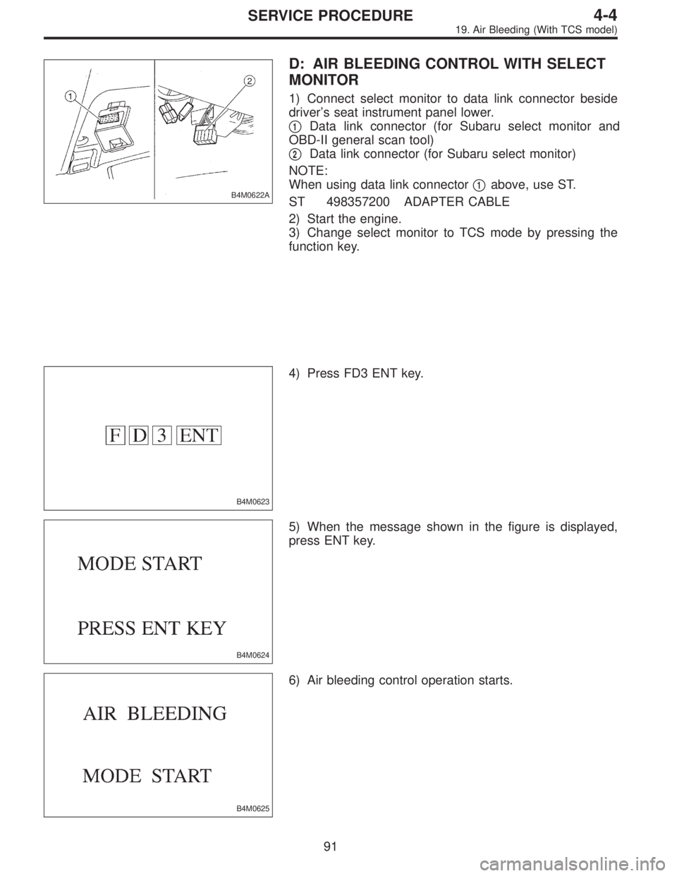
B4M0622A
D: AIR BLEEDING CONTROL WITH SELECT
MONITOR
1) Connect select monitor to data link connector beside
driver’s seat instrument panel lower.
�
1Data link connector (for Subaru select monitor and
OBD-II general scan tool)
�
2Data link connector (for Subaru select monitor)
NOTE:
When using data link connector�
1above, use ST.
ST 498357200 ADAPTER CABLE
2) Start the engine.
3) Change select monitor to TCS mode by pressing the
function key.
B4M0623
4) Press FD3 ENT key.
B4M0624
5) When the message shown in the figure is displayed,
press ENT key.
B4M0625
6) Air bleeding control operation starts.
91
4-4SERVICE PROCEDURE
19. Air Bleeding (With TCS model)
Page 1331 of 2890
B4M1005
7) Remove bolt cover and bolt.
B4M1006
8) Remove ABSCM upper mounting bolt.
B4M1045A
9) Pull the lower part of the instrument panel rearward 5
cm (1.97 in).
CAUTION:
When pulled more than 6 cm (2.4 in), the instrument
panel may be deformed.
NOTE:
At this time, instrument panel securing clips can be
removed.
B4M1008
10) Remove two ABSCM lower mounting bolts from the
lower part of the instrument panel.
B4M1009A
11) While holding the lower part of instrument panel rear-
ward 5 cm (1.97 in) remove the ABSCM.
CAUTION:
When pulled more than 6 cm (2.4 in), the instrument
panel may be deformed.
12) Disconnect connector from ABSCM.
CAUTION:
Do not drop or bump ABSCM.
120
4-4SERVICE PROCEDURE
23. ABS Control Module (ABS 5.3 Type)

 Remove bolt cover and bolt.
B4M1006
8) Remove ABSCM upper mounting bolt.
B4M1045A
9) Pull the lower part of the instrument panel rearward 5
cm (1.97 in).
CAUTION:
When pulled more than 6 cm")