1996 SUBARU LEGACY instrument panel
[x] Cancel search: instrument panelPage 155 of 2890

SUPPLEMENTAL
RESTRAINT
SYSTEM
(ELECTRIC
SENSOR
TYPE)
[T5H11
5-5b
5
.
Diagnostics
Chart
with
Trouble
Code
H
:
TROUBLE
CODE
31
DIAGNOSIS
:
"
Airbag
control
module
is
faulty
.
"
Airbag
main
harness
circuit
is
open
.
"
Fuse
No
.
16
is
blown
.
"
Body
harness
circuit
is
open
.
1
1
.
Airbag
control
module
inspection
1
2
.
Airbag
main
harness
Inspection
1
3
.
Fuse
No
.
16
inspection
CAUTION
:
Before
performing
diagnostics
on
airbag
system,
turn
ignition
switch
"OFF",
disconnect
battery
ground
cable
and
then
wait
at
least
20
seconds
.
After
20
seconds
elapse,
remove
instrument
panel
lower
cover,
and
disconnect
(AB3)
and
(AB8),
(AB9)
and
(AB10)
.
1
.
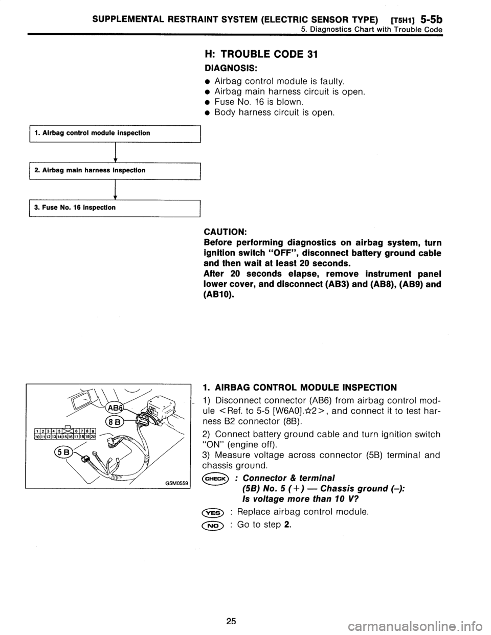
AIRBAG
CONTROL
MODULE
INSPECTION
1)
Disconnect
connector
(AB6)
fromairbag
control
mod-
ule
<
Ref
.
to
5-5
[W6A0].*2
>,
and
connect
it
to
test
har-
ness
B2
connector
(8B)
.
2)
Connect
battery
ground
cable
and
turn
ignition
switch
"ON"
(engine
off)
.
3)
Measure
voltage
across
connector
(5B)
terminal
and
chassis
ground
.
CHECK
:
Connector
&
terminal
(5B)
No
.
5
(+)
-
Chassis
ground
(
)
:
Is
voltage
more
than10
V?
Replace
airbag
control
module
.
No
:
Go
to
step
2
.
25
Page 158 of 2890
![SUBARU LEGACY 1996 Service Repair Manual
5-5b
[TWO]
SUPPLEMENTAL
RESTRAINT
SYSTEM
(ELECTRIC
SENSOR
TYPE)
5
.
Diagnostics
Chart
with
Trouble
Code
J
:
TROUBLE
CODE
34
DIAGNOSIS
:
9
Airbag
main
harness
circuit
(Passenger)
is
shorted
to
po SUBARU LEGACY 1996 Service Repair Manual
5-5b
[TWO]
SUPPLEMENTAL
RESTRAINT
SYSTEM
(ELECTRIC
SENSOR
TYPE)
5
.
Diagnostics
Chart
with
Trouble
Code
J
:
TROUBLE
CODE
34
DIAGNOSIS
:
9
Airbag
main
harness
circuit
(Passenger)
is
shorted
to
po](/manual-img/17/57433/w960_57433-157.png)
5-5b
[TWO]
SUPPLEMENTAL
RESTRAINT
SYSTEM
(ELECTRIC
SENSOR
TYPE)
5
.
Diagnostics
Chart
with
Trouble
Code
J
:
TROUBLE
CODE
34
DIAGNOSIS
:
9
Airbag
main
harness
circuit
(Passenger)
is
shorted
to
power
supply
.
*Airbag
module
harness
(Passenger)
is
shorted
to
power
supply
.
9
Airbag
control
module
is
faulty
.
r
1
.
Airbag
main
harness
inspection
l
CAUTION
:
Before
performing
diagnostics
on
airbag
system,
turn
ignition
switch
"OFF",
disconnect
battery
ground
termi-
nal
and
thenwait
at
least
20
seconds
.
After
20
seconds
elapse,
remove
instrumentpanel
lower
cover,
and
disconnect
(AB3)
and
(AB8),
(AB9)
and
(AB10)
.
1
.
AIRBAG
MAIN
HARNESS
INSPECTION
1)
Disconnect
connector
(AB6)
from
airbag
control
mod-
ule
<
Ref
.
to
5-5
[W6A0].*2
>,
and
connect
it
totest
har-
ness
132
connector
(8B)
.
2)
Connect
battery
ground
cable
and
turn
ignition
switch
"ON"
(engine
off)
.
3)
Measure
voltage
across
each
test
harness
132
connec-
tor
(5B)
terminal
and
chassis
ground
.
CHECK
:
Connector
&
terminal
(5B)
No
.
6
(+)
-
Chassis
ground
(
)
:
Is
voltage
less
than
1
V?
ves
:
Go
to
next
CHECK
No
:
Replace
airbag
main
harness
.
CHECK
;
Connector
&
terminal
(5B)
No
.
7
(+)
-
Chassis
ground
(
)
:
Is
voltage
less
than
1
V?
,rES
:
Replace
airbag
control
module
.
No
:
Replace
airbag
main
harness
.
28
Page 159 of 2890
![SUBARU LEGACY 1996 Service Repair Manual
SUPPLEMENTAL
RESTRAINT
SYSTEM
(ELECTRIC
SENSOR
TYPE)
[T5K1]
5-Sb
5
.
Diagnostics
Chart
with
Trouble
Code
K
:
TROUBLE
CODE
41
DIAGNOSIS
:
Airbag
main
harness
circuit
(Driver)
is
shorted
to
ground SUBARU LEGACY 1996 Service Repair Manual
SUPPLEMENTAL
RESTRAINT
SYSTEM
(ELECTRIC
SENSOR
TYPE)
[T5K1]
5-Sb
5
.
Diagnostics
Chart
with
Trouble
Code
K
:
TROUBLE
CODE
41
DIAGNOSIS
:
Airbag
main
harness
circuit
(Driver)
is
shorted
to
ground](/manual-img/17/57433/w960_57433-158.png)
SUPPLEMENTAL
RESTRAINT
SYSTEM
(ELECTRIC
SENSOR
TYPE)
[T5K1]
5-Sb
5
.
Diagnostics
Chart
with
Trouble
Code
K
:
TROUBLE
CODE
41
DIAGNOSIS
:
Airbag
main
harness
circuit
(Driver)
is
shorted
to
ground
.
"
Airbag
module
harness
(Driver)
is
shorted
to
ground
.
"
Roll
connector
circuit
is
shorted
to
ground
.
"
Airbag
control
module
is
faulty
.
1.
Airbag
main
harness
Inspection
CAUTION
:
Before
performing
diagnostics
on
airbag
system,
turn
ignition
switch
"OFF",
disconnect
battery
ground
cable
and
then
wait
at
least
20
seconds
.
After
20
seconds
elapse,
remove
instrument
panel
lower
cover,
and
disconnect(AB3)
and
(AB8),
(AB9)
and
(AB10)
.
12
3
4
5
67
89
1
10
1
11
1
12
1
13
1
14
1
15
1
16
1
17
1
18
1
19
1
2
01
8B
i
GSM0559
I
1
.
AIRBAG
MAIN
HARNESS
INSPECTION
1)
Disconnect
connector
(AB6)
from
airbag
control
mod-
ule
<
Ref
.
to
5-5
[W6A0].*2
>,
and
connect
it
to
test
har-
ness
B2
connector
(8B)
.
2)
Measure
resistance
between
test
harness
132
connec-
tor
(5B)
terminals
and
chassis
ground
.
CHECK
:
Connector
&
terminal
(58)
No
.
1
(+)
-
Chassis
ground
(
)
:
is
resistance
more
than
200
S2?
Go
to
next
CHECK
No
:
Replace
airbag
main
harness
.
CHECK
:
Connector&
terminal
(5B)
No
.
14
(+)
-
Chassis
ground
(
)
:
Is
resistance
more
than
200
S2?
0
:
Replace
airbag
control
module
.
No
:
Replace
airbag
main
harness
.
29
Page 160 of 2890
![SUBARU LEGACY 1996 Service Repair Manual
5-5b
[750]
SUPPLEMENTAL
RESTRAINT
SYSTEM
(ELECTRIC
SENSOR
TYPE)
5
.
Diagnostics
Chart
with
Trouble
Code
L
:
TROUBLE
CODE
42
DIAGNOSIS
:
*
Airbag
main
harness
circuit
(Passenger)
is
shorted
to
gr SUBARU LEGACY 1996 Service Repair Manual
5-5b
[750]
SUPPLEMENTAL
RESTRAINT
SYSTEM
(ELECTRIC
SENSOR
TYPE)
5
.
Diagnostics
Chart
with
Trouble
Code
L
:
TROUBLE
CODE
42
DIAGNOSIS
:
*
Airbag
main
harness
circuit
(Passenger)
is
shorted
to
gr](/manual-img/17/57433/w960_57433-159.png)
5-5b
[750]
SUPPLEMENTAL
RESTRAINT
SYSTEM
(ELECTRIC
SENSOR
TYPE)
5
.
Diagnostics
Chart
with
Trouble
Code
L
:
TROUBLE
CODE
42
DIAGNOSIS
:
*
Airbag
main
harness
circuit
(Passenger)
is
shorted
to
ground
.
*
Airbag
module
harness
circuit
(Passenger)
is
shorted
to
ground
.
e
Airbag
control
module
is
faulty
.
1
.
Airbag
main
harness
Inspection
CAUTION
:
Before
performing
diagnostics
on
airbag
system,
turn
ignition
switch
"OFF",
disconnect
battery
ground
cable
and
then
wait
at
least
20
seconds
.
After
20
seconds
elapse,
remove
instrument
panel
lower
cover,
and
disconnect
(AB3)
and
(AB8),
(AB9)
and
(AB10)
.
1
.
AIRBAG
MAIN
HARNESS
INSPECTION
1)
Disconnect
connector
(AB6)
from
airbag
control
mod-
ule
<
Ref
.
to
5-5
[W6A0]
.*2>,
and
connect
it
to
test
har-
ness
132
connector
(8B)
.
2)
Measure
resistance
between
test
harness
132
connec-
tor
(5B)
terminals
and
chassis
ground
.
CHECK
;
Connector
&
terminal
(5B)
No
.
6
(+)
-
Chassis
ground
(
)
:
Is
resistance
more
than
200
S2?
,mss
:
Go
to
next
CHECK
No
:
Replace
airbag
main
harness
.
CHECK
:
Connector
&
terminal
(5B)
No
.
7
(+)
-
Chassis
ground
(-)
:
Is
resistance
more
than
200
0?
YES
:
Replace
airbag
control
module
.
No
:
Replace
airbag
main
harness
.
30
Page 161 of 2890
![SUBARU LEGACY 1996 Service Repair Manual
SUPPLEMENTAL
RESTRAINT
SYSTEM
(ELECTRIC
SENSOR
TYPE)
[T5M1]
5-5b
5
.
Diagnostics
Chart
with
Trouble
Code
1.
Airbag
main
harness
Inspection
M
:
TROUBLE
CODE
43
DIAGNOSIS
:
*
Airbag
main
harness
c SUBARU LEGACY 1996 Service Repair Manual
SUPPLEMENTAL
RESTRAINT
SYSTEM
(ELECTRIC
SENSOR
TYPE)
[T5M1]
5-5b
5
.
Diagnostics
Chart
with
Trouble
Code
1.
Airbag
main
harness
Inspection
M
:
TROUBLE
CODE
43
DIAGNOSIS
:
*
Airbag
main
harness
c](/manual-img/17/57433/w960_57433-160.png)
SUPPLEMENTAL
RESTRAINT
SYSTEM
(ELECTRIC
SENSOR
TYPE)
[T5M1]
5-5b
5
.
Diagnostics
Chart
with
Trouble
Code
1.
Airbag
main
harness
Inspection
M
:
TROUBLE
CODE
43
DIAGNOSIS
:
*
Airbag
main
harness
circuit
(Driver)
is
shorted
to
power
supply
.
Airbag
module
harness
(Driver)
is
shorted
to
power
supply
.
"
Roll
connector
is
shorted
to
power
supply
.
"
Airbag
control
module
is
faulty
.
CAUTION
:
Before
performing
diagnostics
on
airbag
system,
turn
ignition
switch
"OFF",
disconnect
battery
ground
termi-
nal
and
thenwait
at
least
20
seconds
.
After
20
seconds
elapse,
remove
instrument
panel
lower
cover,
and
disconnect
(AB3)
and
(AB8),
(AB9)
and
(AB10)
.
1
.
AIRBAG
MAIN
HARNESS
INSPECTION
1)
Disconnect
connector
(AB6)from
airbag
control
mod-
ule
<
Ref
.
to
5-5
[W6A0]
.*2>,
and
connect
it
to
test
har-
ness
132
connector
(8B)
.
2)
Connect
battery
ground
cable
and
turn
ignition
switch
"ON"
(engine
off)
.
3)
Measure
voltage
across
each
test
harness
132
connec-
tor
(5B)terminal
and
chassis
ground
.
CHECK
:
Connector
&
terminal
(5B)
No
.
1
(+)
-
Chassis
ground
(
)
:
Is
voltage
less
than
1
V?
YES
.
G
o
tonext
CHECK
No
:
Replace
airbag
main
harness
.
CHECK
:
Connector&
terminal
(58)
No
.
14
(+)
-
Chassis
ground
(-)
:
Is
voltage
less
than
1
V?
vES
:
Replace
airbag
control
module
.
No
:
Replace
airbag
main
harness
.
31
Page 163 of 2890
![SUBARU LEGACY 1996 Service Repair Manual
SUPPLEMENTAL
RESTRAINT
SYSTEM
(ELECTRIC
SENSOR
TYPE)
[T5N2]
5-5b
5
.
Diagnostics
Chart
with
Trouble
Code
B31
1A
5A
r
.~
..
,fl((
i
1
23
45B
7
89
101
.112131415
761718
I
B5M0123B
i
1
2
31
5
87 SUBARU LEGACY 1996 Service Repair Manual
SUPPLEMENTAL
RESTRAINT
SYSTEM
(ELECTRIC
SENSOR
TYPE)
[T5N2]
5-5b
5
.
Diagnostics
Chart
with
Trouble
Code
B31
1A
5A
r
.~
..
,fl((
i
1
23
45B
7
89
101
.112131415
761718
I
B5M0123B
i
1
2
31
5
87](/manual-img/17/57433/w960_57433-162.png)
SUPPLEMENTAL
RESTRAINT
SYSTEM
(ELECTRIC
SENSOR
TYPE)
[T5N2]
5-5b
5
.
Diagnostics
Chart
with
Trouble
Code
B31
1A
5A
r
.~
..
,fl((
i
1
23
45B
7
89
101
.112131415
761718
I
B5M0123B
i
1
2
31
5
8789
[
lo
l
l1
1
12
1
13
1
14
1
15
1
16
1
17
1
.
t18
20
i
G5M0559
I
2
.
INSPECTION
OF
BODY
HARNESS,
CONNECTOR
AND
AIRBAG
WARNING
LIGHT
1)
Turn
ignition
switch
"OFF"
and
connect
body
harness
connector
(B31)
to
test
connector
A
connector
(1A)
.
2)
Connect
battery
ground
cable
and
turn
ignition
switch
"ON",
(engine
off)
and
connect
connectors
(3A)
and
(4A)
.
CHECK
;
Does
the
airbag
warning
light
come
off?
,rES
:
Go
tostep
3)
.
Go
tonext
~
.
~K
:
Is
there
anything
unusual
to
body
harness?
Repair
body
harness
.
Replace
airbag
warning
light
module
1~
.
NOTE
:
After
problem
has
been
eliminated,
disconnect
connectors
(3A)
and
(4A)
.
3)
Turn
ignition
switch
"OFF",
disconnect
battery
ground
cable
and
then
wait
at
least
20
seconds,
and
re-connect
connectors
(AB1)
and
(B31)
.
4)
Remove
instrument
panel
lower
cover
and
disconnect
(AB3)
with
(AB8),
then
disconnect
connector
(AB6)from
airbag
control
module,
<
Ref
.
to
5-5
[W6A0]
.*2
>
and
connect
it
to
test
harness
132
connector
(8B)
.
5)
Connect
battery
ground
cable
and
turn
ignition
switch
"ON,"
(engine
off)
and
connect
connectors
(6B)
and
(7B)
.
CHECK
:
Does
the
airbag
warning
light
come
on?
0
:
Go
to
step
3
.
No
:
Replace
airbag
main
harness
.
NOTE
:
After
problem
has
been
eliminated,
disconnect
connectors
(6B)
and
(7B)
.
33
Page 190 of 2890

r
Connecting
to
)r
Area
No
.
Name
C-4
D1
Front
doorcord
RH
ow
C-4
ABi
SRS
(Airbag)
harness
;k
C-4
Turn
&
hazard
module
.k
C-3
i1
C-3
i2
instrument
panel
wiring
un
C-3
i3
harness
e
C-3
i4
y
C-3
OBD-IIservice
connector
C-3
Power
window
circuit
breaker
C-3
Power
window
relay
;k
C-3
Illuminationcontrol
module
C-3
Seat
belt
timer
;n
B-4
Fuel
pump
relay
vn
B-4
Main
relay
;k
B-4
Horn
relay
B-4
Blower
relay
y
C-4
FIB
y
C-4
B-3
Shield
joint
connector
(AT)
.k
B-3
:k
B-3
Transmission
control
module
.k
B-3
:k
B-3
Shift-lock
control
module
B-4F44
i
h
B-4F45
Front
w
ring
arness
.k
B-3
Stop
light
switch
,k
B-3
Stop
8
brake
switch
(Withcruise
control)
:k
8-3
Cruise
control
sub
switch
Connector
Connecting
to
No
.
Pole
Color
Area
No
.
Name
869
11
Black
C-3
B70
9
C-3
Combination
switch
B71
8
8-3
B72
6
Black
C-3
Ignition
switch
B73
2
Black
B-3
Key
lock
solenoid
B74
2
Black
B-3
Key
warning
switch
B75
2
Green
B-2
876
T
d
B76
2
Green
8-2
875
e
connector
est
mo
877
7
B-2
Mode
actuator
B78
9
Yellow
B-2
Data
link
connector
B79
14
Gray
C-2
Check
connector
BBO
4
Blue
B-2
i20
Instrument
panel
wiring
harness
B81
1
x
2
B-2
Diagnosis
terminal
(Ground)
B82
6
Black
B-2
Diagnosisconnector
BB3
4
C-1
Shield
joint
connector
(EIG)
BBQ
96Lightblue
C-2
Engine
control
module
B85
4
Brown
B-3
Diode
(Lighting)
B86
4
Black
B-1
Blower
motor
resistor
887
2
Black
B-1
Blower
motor
888
3
Black
B-1
Evaporatorthermoswitch
B90
2
Green
B-4
R50
Room
light
cord
B91
5
B-1
FRESHIRECIRC
actuator
B92
8
B-1
Door
lock
timer
894
20
Black
B-1
Cruise
control
module
B97
56
B-4
R1
Rear
wiring
harness
(S.M
.J
.)
B101
24
B-1
D11
Front
door
cord
LH
8111
3
Gray
C-4FIB
`
:
Non-colored
4
.
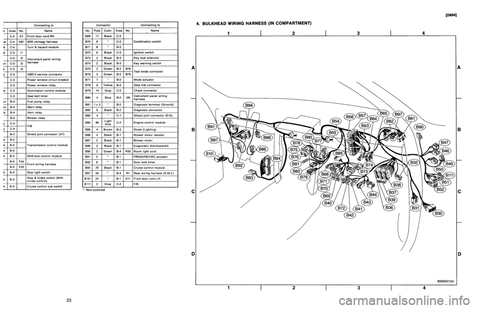
BULKHEAD
WIRING
HARNESS
(IN
COMPARTMENT)
1
I
2
I
3
I
4
A
B
C
D
1
I
2
I
3
I
4
[oeo41
B6M0513A
A
B
C
iJ
23
Page 191 of 2890

Connector
Connecting
to
No
.
Pole
Color
Area
No
.
Name
830
24
C-4
D1
Front
door
cord
RH
831
7
Yellow
C-4
A81
SRS
(Airbag)
harness
B32
3
Black
C-4
Turn
&
hazard
module
B36
22
Black
C-3
i1
B37
22
C-3
i2
Instrument
panel
wiring
B38
22
Brown
C-3
i3
harness
B39
20Blue
C-3
i4
B40
16
Gray
C-3
OBD-II
service
connector
B41
2
C-3
Power
window
circuit
breaker
842
4
C-3
Power
window
relay
B43
6
Black
C-3
Illumination
control
module
B44
8
C-3
Seat
belt
timer
B46
4
Green
B-4
Fuel
pump
relay
B47
6
Brown
B-4
Main
relay
B49
3
Black
B-4
Horn
relay
850
4
B-4
Blower
relay
851
11
Gray
C-4
FIB
B52
12
Gray
C-4
853
4
B-3
Shield
joint
connector
(AT)
B54
12
Black
B-3
B55
16
Black
B-3
Transmission
control
module
B56
20
Black
B-3
B57
12
Black
B-3
Shift-lock
control
module
861
B
B-4
F44
B62
20
B-4
F45
Front
wiring
harness
B64
2
Black
B-3
Stop
light
switch
B65
4
Black
B-3
Stop
&
brake
switch(Withcruise
control)
B68
5
i
Black
i
B-3
Cruise
control
sub
switch
Connector
Connecting
to
No
.
Pole
Color
Area
No
.
Name
B69
11
Black
C-3
B70
9
C-3
Combination
switch
B71
8
8-3
B72
6
Black
C-3
Ignition
switch
B73
2
Black
B-3
Key
lock
solenoid
B74
2
Black
B-3
Key
warning
switch
B75
2
Green
B-2
B76
B76
2
Green
&2
B75
Test
mode
connector
B77
7
B-2
Made
actuator
B78
9
Yellow
B-2
Data
link
connector
B79
14
Gray
C-2
Check
connector
B80
4
Blue
B-2
i20
Instrumentpanel
wiring
harness
B81
1
x
2
B-2
Diagnosis
terminal
(Ground)
B82
6
Black
B-2
Diagnosis
connector
B83
4
C-1
Shield
joint
connector
(E!G)
884
96
Light
blue
C-2
Engine
control
module
885
4
Brown
B-3
Diode
(Lighting)
B86
4
Black
B-1
Blower
motor
resistor
887
2
Black
B-1
Blower
motor
B88
3
Black
8-t
Evaporator
thermoswitch
890
2
Green
B-4
R50
Room
light
cord
B91
5B-1
FRESHIRECIRC
actuator
892
8
B-1
Door
lock
timer
B94
20
Black
B-1
Cruise
control
module
B97
56
B-4
R1Rear
wiring
harness
(S
.M
.J
.)
B101
24
B-1
D11
Front
doorcord
LH
13111
3
Gray
C-4
FIB
`
:
Non-colored
4
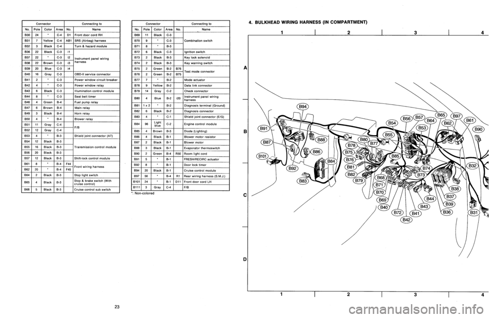
.
BULKHEAD
WIRING
HARNESS
(IN
COMPARTMENT)
A
B
C
1]
4
23