Page 2688 of 2890
 Turn ignition switch“OFF”and connect body harness
connector (B31) to test connector A connector (1A).
G5M0455
2) Conne")
B5M0123B
2. INSPECTION OF BODY HARNESS, CONNECTOR
AND AIRBAG WARNING LIGHT
1) Turn ignition switch“OFF”and connect body harness
connector (B31) to test connector A connector (1A).
G5M0455
2) Connect battery ground cable and turn ignition switch
“ON”, (engine off) and connect connectors (3A) and (4A).
: Does the airbag warning light come off?
: Go to step 3).
: Go to next.
B5M0124A
: Is there anything unusual to body harness?
: Repair body harness.
: Replace airbag warning light module�1.
NOTE:
After problem has been eliminated, disconnect connectors
(3A) and (4A).
G5M0559
3) Turn ignition switch“OFF”, disconnect battery ground
cable and then wait at least 20 seconds, and re-connect
connectors (AB1) and (B31).
4) Remove instrument panel lower cover and disconnect
(AB3) with (AB8), then disconnect connector (AB6) from
airbag control module, and connect
it to test harness B2 connector (8B).
G5M0458
5) Connect battery ground cable and turn ignition switch
“ON,”(engine off) and connect connectors (6B) and (7B).
: Does the airbag warning light come on?
: Go to step3.
: Replace airbag main harness.
NOTE:
After problem has been eliminated, disconnect connectors
(6B) and (7B).
34
5-5bSUPPLEMENTAL RESTRAINT SYSTEM (ELECTRIC SENSOR TYPE)
5. Diagnostics Chart with Trouble Code
Page 2732 of 2890
1. General Description
1. HOW TO USE THIS MANUAL
The description of the electrical system is divided into the
charging system, starting system, etc.
1) First, open to the necessary electrical system section
and wiring diagram.
2) Next, open the foldout page of the electrical wiring dia-
gram. By observing the electrical wiring harness’ illustra-
tions (front, instrument panel, etc.), the wiring diagram con-
nector can be located.
G6M0192
G6M0193
2. WIRING DIAGRAM
The wiring diagram of each system is illustrated so that you
can understand the path through which the electric current
flows from the battery.
Sketches and codes are used in the diagrams. They should
read as follows:
1) Each connector and its terminal position are indicated
by a sketch of the connector in a disconnected state which
is viewed from the front, as shown in figure.
2
6-3WIRING DIAGRAM
1. General Description
Page 2737 of 2890
G6M0205
11) Each connector number shown in the wiring diagram
corresponds to that in the wiring harness. The location of
each connector in the actual vehicle is determined by read-
ing the first character of the connector (for example, a“F”
for F8,“i”for i16, etc.) and the type of wiring harness.
The first character of each connector number refers to the
area or system of the vehicle, as indicated in table below.
Symbol Wiring harness and Cord
F Front wiring harness
B Bulkhead wiring harness
E Engine wiring harness
T Transmission cord
D Door cord LH & RH, Rear gate cord
I Instrument panel wiring harness
RRear wiring harness, Rear defogger cord
Room light cord,
Fuel tank cord,
Sunroof cord,
Trunk lid cord
P Floor wiring harness
7
6-3WIRING DIAGRAM
1. General Description
Page 2839 of 2890
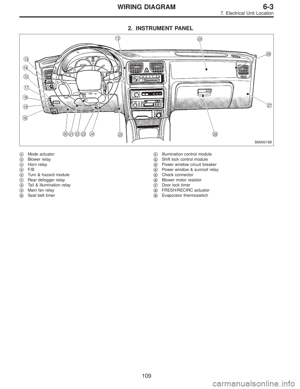
2. INSTRUMENT PANEL
B6M0218B
�12Mode actuator
�
13Blower relay
�
14Horn relay
�
15F/B
�
16Turn & hazard module
�
17Rear defogger relay
�
18Tail & illumination relay
�
19Main fan relay
�
20Seat belt timer�
21Illumination control module
�
22Shift lock control module
�
23Power window circuit breaker
�
24Power window & sunroof relay
�
25Check connector
�
26Blower motor resistor
�
27Door lock timer
�
28FRESH/RECIRC actuator
�
29Evaporator thermoswitch
109
6-3WIRING DIAGRAM
7. Electrical Unit Location
Page 2843 of 2890
8. Electrical Wiring Harness and
Ground Point
B6M0267A
�1Front wiring harness
�
2Engine wiring harness
�
3Room light cord
�
4Bulkhead wiring harness
�
5Instrument panel wiring harness
�
6Front door cord RH
�
7Rear door cord RH
�
8Rear wiring harness
�
9Trunk lid cord (Sedan)�
10Rear defogger ground cord (Sedan)
�
11Fuel tank cord
�
12Rear door cord LH
�
13Front door cord LH
�
14Sunroof cord
�
15Floor wiring harness
�
16Transmission cord
�
17Rear gate cord (Wagon)
�
18Rear oxygen sensor cord
11 3
6-3WIRING DIAGRAM
8. Electrical Wiring Harness and Ground Point
Page 2855 of 2890
 harness
B32 3 Black C-1 Turn & hazard module
B33 4 Brown B-1 Diode (Brake flui")
Connector Connecting to
No. Pole Color Area No. Name
B30 24 * C-1 D1 Front door cord LH
B31 7 Yellow C-1 AB1 SRS (Airbag) harness
B32 3 Black C-1 Turn & hazard module
B33 4 Brown B-1 Diode (Brake fluid level)
B34 3 * B-1 Diode (Door warning)
B35 2 Black B-1 Diode (Step light)
B36 22 Black C-1 i1
Instrument panel wiring
harness B37 22 * C-1 i2
B38 22 Brown C-1 i3
B39 20 Blue C-1 i4
B40 16 Gray C-2 OBD-II service connector
B41 2 * C-2 Power window circuit breaker
B42 4 * C-2Power window and sunroof
relay
B43 6 Black C-2 Illumination control module
B44 8 * C-2 Seat belt timer
B45 4 * B-1 R53 Sunroof cord
B46 4 Green B-1 Fuel pump relay
B47 6 Brown B-1 Main relay
B48 4 Blue B-1 Front fog light relay
B49 3 Black B-1 Horn relay
B50 4 * B-1 Blower relay
B51 11 Gray B-1
F/B
B52 12 Gray B-1
B53 4 * B-2 Shield joint connector (AT)
B54 12 Black B-2
Transmission control module B55 16 Black B-2
B56 20 Black B-2
B57 12 Black B-2 Shift-lock control module
B58 5 Black B-1Headlight alarm relay
(Security)
B59 5 Black B-1 Interrupt relay (Security)
B60 4 * B-2Shield joint connector (With
TCS model)
B61 8 * B-2 F44
Front wiring harness
B62 20 * B-1 F45
B63 40 Gray B-1 P10Floor harness (With TCS
model)
B64 2 Black B-2 Stop light switch
B65 4 Black B-2Stop & brake switch (With
cruise control)
B66 3 Black B-2 Pedal stroke sensor (TCS)
B67 4 Black B-2 Pedal stroke switch (TCS)
B68 5 Black B-3 Slip ring
B69 11 Black B-3
Combination switch B70 9 * B-3
B71 8 * B-3
B72 6 Black B-3 Ignition switchConnector Connecting to
No. Pole Color Area No. Name
B73 2 Black B-3 Key lock solenoid (AT)
B74 2 Black B-3 Key warning switch
B75 2 Green C-2 B76
Test mode connector
B76 2 Green C-3 B75
B77 10 Brown B-2 Mode actuator
B78 9 Yellow C-2 Data link connector
B79 14 Gray C-2 Check connector
B80 4 Blue B-2 i20Instrument panel wiring
harness
B81 1 x 2 * C-2 Diagnosis terminal (Ground)
B82 6 Black C-2 Diagnosis connector
B83 4 * C-3 Shield joint connector (E/G)
B84 96Light
blueB-3 Engine control module
B85 2 Black B-3 Diode (Lighting)
B86 4 * B-3 Blower motor resistor
B87 2 * B-3 Blower motor
B88 3 Black B-3 Evaporator thermoswitch
B89 4 Brown B-3 Diode (Security)
B90 4 * B-4 R50 Room light cord
B91 4 * B-4 FRESH/RECIRC actuator
B92 8 * B-4 Door lock timer
B93 16 Black B-4 Security control module
B94 20 Black B-4 Cruise control module
B95 2 Black B-4 Diode (Daytime running light)
B96 10 * B-4Daytime running light control
module
B97 8 * B-4 R1
Rear wiring harness B98 24 Black B-4 R2
B99 24 * B-4 R3
B100 20 Blue B-4 F2Front wiring harness (With
ABS model)
B101 24 * B-4 D11 Front door cord RH
B102 5 Black B-4 Daytime running light relay
B103 4 Blue B-4High-beam relay (Daytime
running light)
B104 4 Pink B-4 Rear power supply relay
B105 4 Blue B-1 Starter interlock relay (MT)
B106 2 * B-1 Clutch switch (MT)
B107 2 Blue B-1 Clutch switch (Cruise control)
B108 2 Black B-2 F46Front wiring harness
(Outback)
B109 4 Black C-1 Fuse holder (Outback)
B112 2 Black B-1 Diode (Front fog light)
*: Non-colored
Connector Connecting to
No. Pole Color Area No. Name
S1 3 White D-3 Cruise control sub switch
125
6-3WIRING DIAGRAM
8. Electrical Wiring Harness and Ground Point
Page 2857 of 2890
 harness
B32 3 Black C-4 Turn & hazard module
B36 22 Black C-3 i1
Instrument pa")
Connector Connecting to
No. Pole Color Area No. Name
B30 24 * C-4 D1 Front door cord RH
B31 7 Yellow C-4 AB1 SRS (Airbag) harness
B32 3 Black C-4 Turn & hazard module
B36 22 Black C-3 i1
Instrument panel wiring
harness B37 22 * C-3 i2
B38 22 Brown C-3 i3
B39 20 Blue C-3 i4
B40 16 Gray C-3 OBD-II service connector
B41 2 * C-3 Power window circuit breaker
B42 4 * C-3 Power window relay
B43 6 Black C-3 Illumination control module
B44 8 * C-3 Seat belt timer
B46 4 Green B-4 Fuel pump relay
B47 6 Brown B-4 Main relay
B49 3 Black B-4 Horn relay
B50 4 * B-4 Blower relay
B51 11 Gray C-4
F/B
B52 12 Gray C-4
B53 4 * B-3 Shield joint connector (AT)
B54 12 Black B-3
Transmission control module B55 16 Black B-3
B56 20 Black B-3
B57 12 Black B-3 Shift-lock control module
B61 8 * B-4 F44
Front wiring harness
B62 20 * B-4 F45
B64 2 Black B-3 Stop light switch
B65 4 Black B-3Stop & brake switch (With
cruise control)
B68 5 Black B-3 Cruise control sub switchConnector Connecting to
No. Pole Color Area No. Name
B69 11 Black C-3
Combination switch B70 9 * C-3
B71 8 * B-3
B72 6 Black C-3 Ignition switch
B73 2 Black B-3 Key lock solenoid
B74 2 Black B-3 Key warning switch
B75 2 Green B-2 B76
Test mode connector
B76 2 Green B-2 B75
B77 7 * B-2 Mode actuator
B78 9 Yellow B-2 Data link connector
B79 14 Gray C-2 Check connector
B80 4 Blue B-2 i20Instrument panel wiring
harness
B81 1 x 2 * B-2 Diagnosis terminal (Ground)
B82 6 Black B-2 Diagnosis connector
B83 4 * C-1 Shield joint connector (E/G)
B84 96Light
blueC-2 Engine control module
B85 4 Brown B-3 Diode (Lighting)
B86 4 Black B-1 Blower motor resistor
B87 2 Black B-1 Blower motor
B88 3 Black B-1 Evaporator thermoswitch
B90 2 Green B-4 R50 Room light cord
B91 5 * B-1 FRESH/RECIRC actuator
B92 8 * B-1 Door lock timer
B94 20 Black B-1 Cruise control module
B97 56 * B-4 R1 Rear wiring harness (S.M.J.)
B101 24 * B-1 D11 Front door cord LH
B111 3 Gray C-4 F/B
*: Non-colored
127
6-3WIRING DIAGRAM
8. Electrical Wiring Harness and Ground Point
Page 2858 of 2890
5. INSTRUMENT PANEL WIRING HARNESS AND GROUND POINT
�LHD model
B6M0262A
128
6-3WIRING DIAGRAM
8. Electrical Wiring Harness and Ground Point
 First, open to the necessary electrical system s")
 Each connector number shown in the wiring diagram
corresponds to that in the wiring harness. The location of
each connector in the actual vehicle is determined by read-
ing the first chara")