Page 659 of 1954
Throttle Bod y
Descriptio n
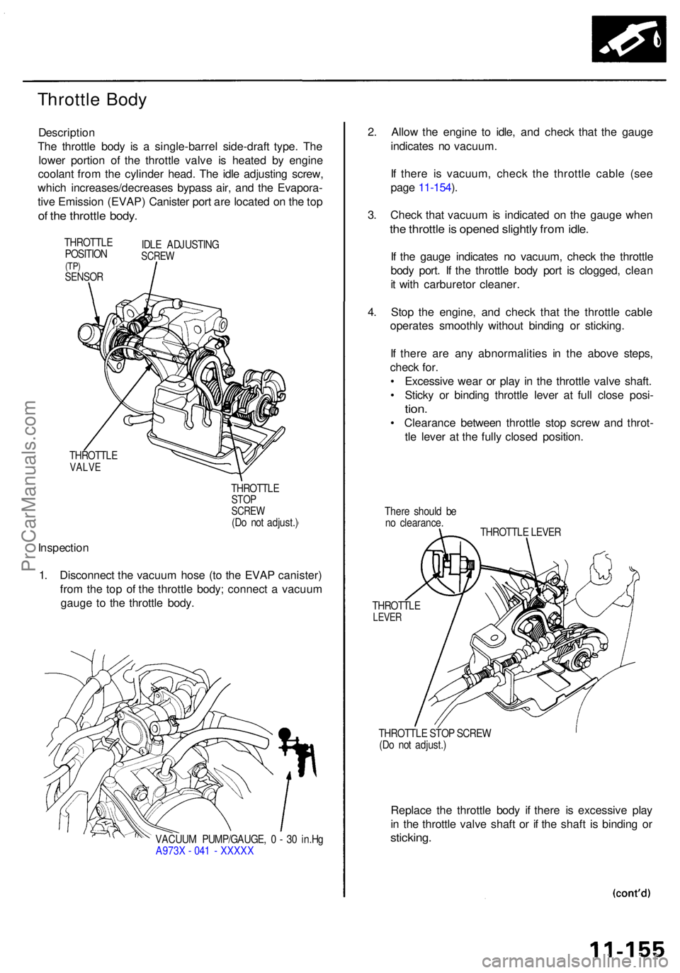
The throttl e bod y i s a single-barre l side-draf t type . Th e
lowe r portio n o f th e throttl e valv e i s heate d b y engin e
coolan t fro m th e cylinde r head . Th e idl e adjustin g screw ,
whic h increases/decrease s bypas s air , an d th e Evapora -
tiv e Emissio n (EVAP ) Caniste r por t ar e locate d o n th e to p
of th e throttl e body .
THROTTL E
POSITIO N
(TP)SENSO R
IDLE ADJUSTIN GSCREW
THROTTL EVALVE
THROTTL ESTOPSCRE W(Do no t adjust. )
Inspectio n
1 . Disconnec t th e vacuu m hos e (t o th e EVA P canister )
fro m th e to p o f th e throttl e body ; connec t a vacuu m
gaug e t o th e throttl e body .
VACUU M PUMP/GAUGE , 0 - 3 0 in.H g
A973 X - 04 1 - XXXX X
2. Allo w th e engin e t o idle , an d chec k tha t th e gaug e
indicate s n o vacuum .
I f ther e i s vacuum , chec k th e throttl e cabl e (se e
pag e 11-154 ).
3 . Chec k tha t vacuu m is indicate d o n th e gaug e whe n
the throttl e is opene d slightl y fro m idle .
If th e gaug e indicate s n o vacuum , chec k th e throttl e
bod y port . I f th e throttl e bod y por t i s clogged , clea n
i t wit h carbureto r cleaner .
4 . Sto p th e engine , an d chec k tha t th e throttl e cabl e
operate s smoothl y withou t bindin g o r sticking .
I f ther e ar e an y abnormalitie s i n th e abov e steps ,
chec k for .
• Excessiv e wea r o r pla y i n th e throttl e valv e shaft .
• Stick y o r bindin g throttl e leve r a t ful l clos e posi -
tion.
• Clearanc e betwee n throttl e sto p scre w an d throt -
tl e leve r a t th e full y close d position .
There shoul d b e
n o clearance .
THROTTL E LEVE R
THROTTL E
LEVER
THROTTL E STO P SCRE W
(D o no t adjust. )
Replace th e throttl e bod y i f ther e i s excessiv e pla y
i n th e throttl e valv e shaf t o r i f th e shaf t i s bindin g o r
sticking .
ProCarManuals.com
Page 668 of 1954
Emission Contro l Syste m
System Descriptio n
The emissio n contro l syste m include s a Thre e Wa y Cata -
lyti c Converte r (TWC) , Exhaus t Ga s Recirculatio n (EGR )
system , Positiv e Crankcas e Ventilatio n (PCV ) syste m an d
Evaporativ e Emissio n (EVAP ) system . Th e emissio n contro l
syste m is designe d t o mee t federa l an d stat e emissio n
standards .
Tailpipe Emissio n
Inspection
Do no t smok e durin g thi s procedure . Kee p
an y ope n flam e awa y fro m you r wor k area .
1 . Star t th e engine . Hol d th e engin e a t 3,00 0 rp m wit h
n o loa d (i n Par k o r neutral ) unti l th e radiato r fa n
come s on , the n le t i t idle .
2 . Connec t a tachometer .
3 . Chec k an d adjus t th e idl e speed , i f necessar y (se e
pag e 11-124 ).
4 . War m u p an d calibrat e th e C O mete r accordin g to th e
mete r manufacturer' s instructions .
5 . Chec k idl e C O wit h th e headlights , heate r blower ,
rea r windo w defogger , coolin g fan , an d ai r condition -
er off .
NOTE : (Canada ) Depres s th e parkin g brak e pedal .
Star t th e engine , the n chec k tha t th e headlight s ar e
off.
CO mete r shoul d indicat e 0.1 % maximum .
Three Wa y Catalyti c Converte r
(TWC)
Descriptio n
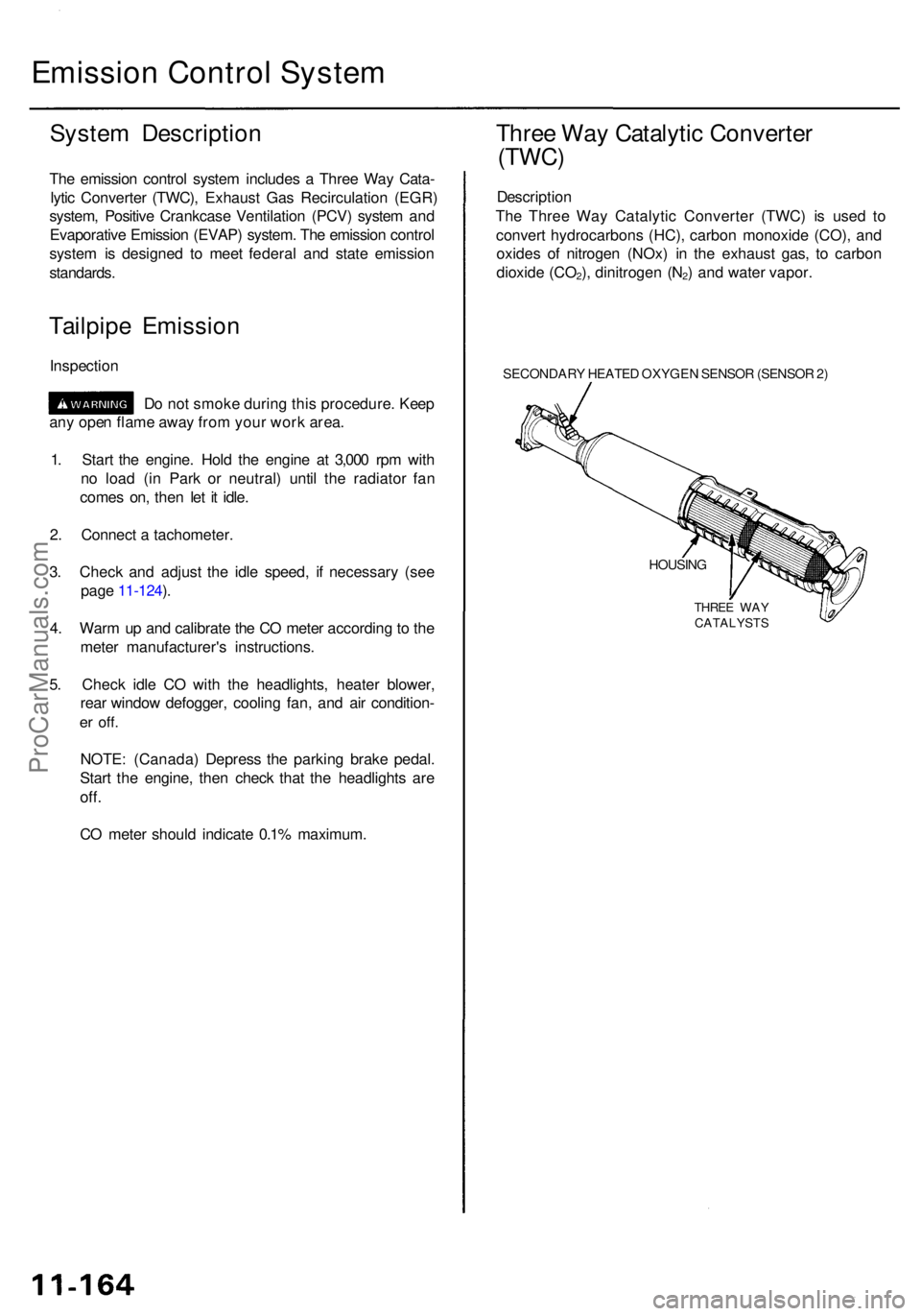
Th e Thre e Wa y Catalyti c Converte r (TWC) is use d t o
conver t hydrocarbon s (HC) , carbo n monoxid e (CO) , an d
oxide s o f nitroge n (NOx) in th e exhaus t gas , t o carbo n
dioxid e (CO
2), dinitroge n (N2) an d wate r vapor .
SECONDAR Y HEATE D OXYGE N SENSO R (SENSO R 2)
HOUSIN G
THREE WA Y
CATALYST S
ProCarManuals.com
Page 678 of 1954
Emission Contro l Syste m
Positiv e Crankcas e Ventilatio n (PCV ) Syste m
Descriptio n
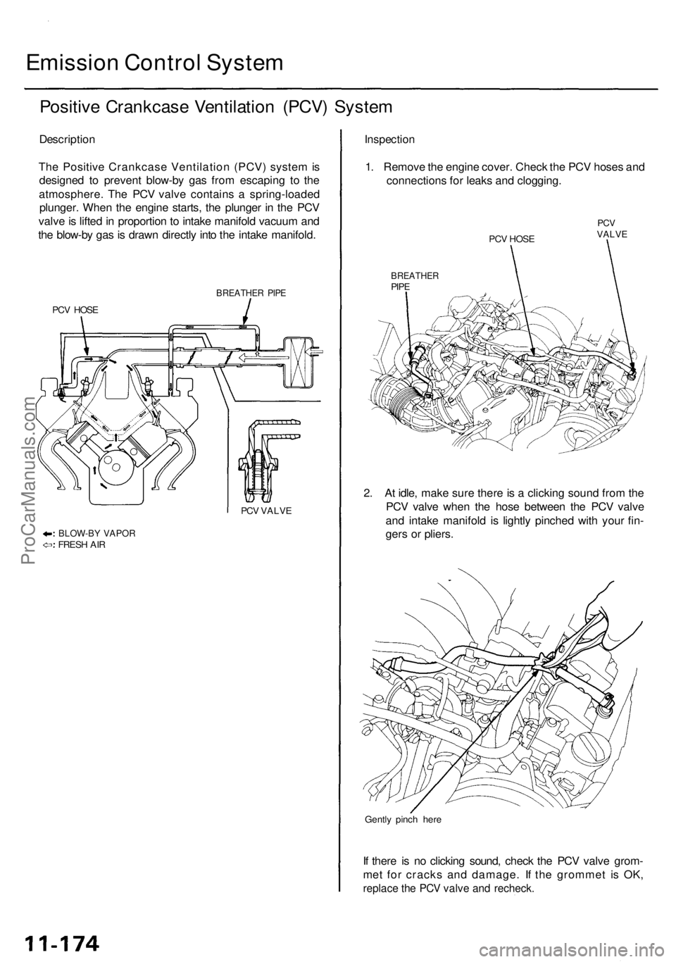
Th e Positiv e Crankcas e Ventilatio n (PCV ) syste m is
designe d t o preven t blow-b y ga s fro m escapin g t o th e
atmosphere . Th e PC V valv e contain s a spring-loade d
plunger . Whe n th e engin e starts , th e plunge r i n th e PC V
valv e is lifte d in proportio n to intak e manifol d vacuu m an d
th e blow-b y ga s is draw n directl y int o th e intak e manifold .
BREATHE R PIP E
PCV HOS E
PCV VALV E
BLOW-B Y VAPO RFRESH AI R
Inspectio n
1. Remov e th e engin e cover . Chec k th e PC V hose s an d
connection s fo r leak s an d clogging .
PCV HOS E
PCVVALV E
BREATHE RPIPE
2. A t idle , mak e sur e ther e is a clickin g soun d fro m th e
PC V valv e whe n th e hos e betwee n th e PC V valv e
an d intak e manifol d i s lightl y pinche d wit h you r fin -
ger s o r pliers .
Gently pinc h her e
If ther e i s n o clickin g sound , chec k th e PC V valv e grom -
me t fo r crack s an d damage . I f th e gromme t i s OK ,
replac e th e PC V valv e an d recheck .
ProCarManuals.com
Page 728 of 1954
Electronic Control System
The electronic control system consists of a Powertrain Control Module (PCM), sensors, a A/T clutch pressure control
solenoid and four solenoid valves. Shifting and lock-up are electronically controlled for comfortable driving under all con-
ditions. The PCM is located below the dashboard, under the front lower panel on the passenger's side.
PCM
Throttle Position Sensor
Signal
Engine Coolant Temperature
Sensor Signal
Indicator Light
Self-Diagnosis Signal
PGM-FI
Control System
Shift Control
Lock-up Control
A/T Control System
Self-Diagnosis
Function
Vehicle Speed Sensor
Signal
Service Check Connector
Shift Solenoid
Valve A
Shift Solenoid
Valve B
A/T Clutch Pressure Control
Solenoid Valve
Torque Converter Clutch
(Lock-up Control)
Solenoid Valve A
Torque Converter Clutch
(Lock-up Control)
Solenoid Valve B
Mainshaft Speed Sensor
Signal
Countershaft Speed
Sensor Signal
Interlock SystemProCarManuals.com
Page 750 of 1954
Partial Lock-up
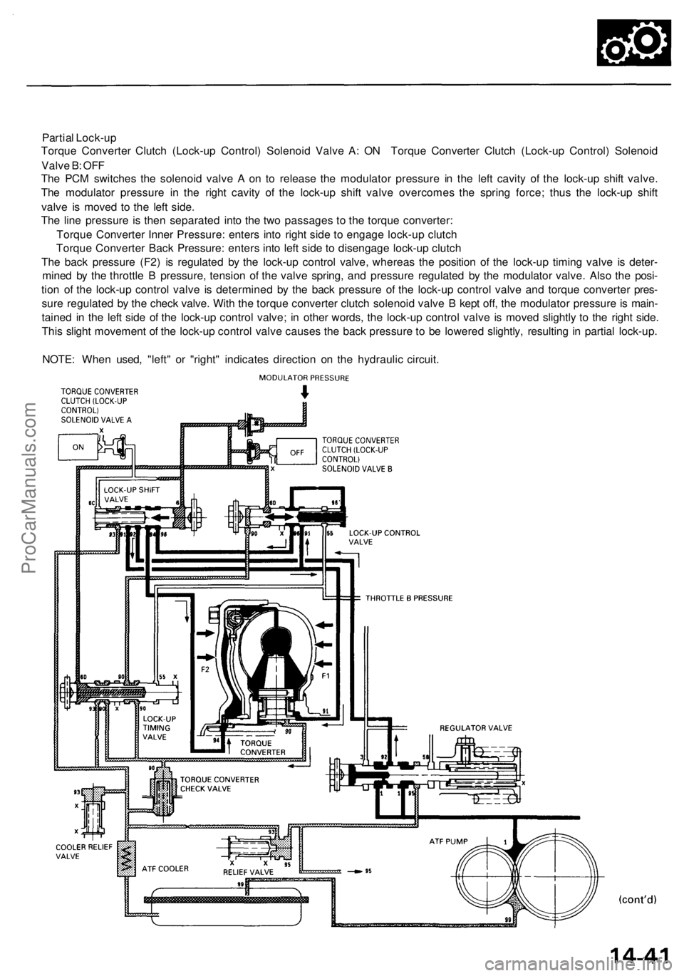
Torque Converter Clutch (Lock-up Control) Solenoid Valve A: ON Torque Converter Clutch (Lock-up Control) Solenoid
Valve B: OFF
The PCM switches the solenoid valve A on to release the modulator pressure in the left cavity of the lock-up shift valve.
The modulator pressure in the right cavity of the lock-up shift valve overcomes the spring force; thus the lock-up shift
valve is moved to the left side.
The line pressure is then separated into the two passages to the torque converter:
Torque Converter Inner Pressure: enters into right side to engage lock-up clutch
Torque Converter Back Pressure: enters into left side to disengage lock-up clutch
The back pressure (F2) is regulated by the lock-up control valve, whereas the position of the lock-up timing valve is deter-
mined by the throttle B pressure, tension of the valve spring, and pressure regulated by the modulator valve. Also the posi-
tion of the lock-up control valve is determined by the back pressure of the lock-up control valve and torque converter pres-
sure regulated by the check valve. With the torque converter clutch solenoid valve B kept off, the modulator pressure is main-
tained in the left side of the lock-up control valve; in other words, the lock-up control valve is moved slightly to the right side.
This slight movement of the lock-up control valve causes the back pressure to be lowered slightly, resulting in partial lock-up.
NOTE: When used, "left" or "right" indicates direction on the hydraulic circuit.ProCarManuals.com
Page 753 of 1954
Description
Lock-up System (cont'd)
Deceleration Lock-up
Torque Converter Clutch (Lock-up Control) Solenoid Valve A: ON Torque Converter Clutch (Lock-up Control) Solenoid
Valve B: Duty Operation
The PCM switches solenoid valve B on and off rapidly under certain conditions. The slight lock-up and half lock-up regions
are maintained so as to lock the torque converter properly.
NOTE: When used, "left" or "right" indicates direction on the hydraulic circuit.ProCarManuals.com
Page 754 of 1954
Park Mechanism
The park mechanism locks the transmission by engaging the park pawl with the park gear which is splined to the counter-
shaft.
Shifting to [3 position causes the park cone (installed at the end of the park rod) to press the park pawl onto the park gear.
Even if the end of the park pawl rides on top of the park gear teeth, slight movement of the countershaft will cause the
park pawl and the park gear to mesh with each other completely because the park cone receives tension from the park rod
spring. The park pawl receives the tension (which acts to separate the park pawl from the park gear) from the park pawl
spring.
COUNTERSHAFT
PARK ROD SPRING
PARK PAWL
PARK GEAR
PARK ROD HOLDER
PARK CONEProCarManuals.com
Page 760 of 1954
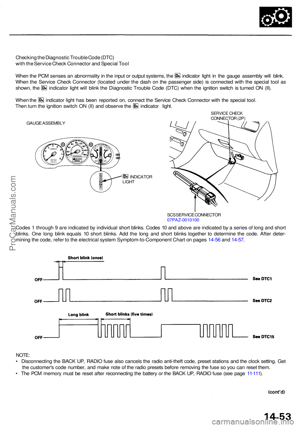
Checking th e Diagnosti c Troubl e Cod e (DTC )
wit h th e Servic e Chec k Connecto r an d Specia l Too l
Whe n th e PC M sense s a n abnormalit y in th e inpu t o r outpu t systems , th e indicato r ligh t i n th e gaug e assembl y wil l blink .
Whe n th e Servic e Chec k Connecto r (locate d unde r th e das h o n th e passenge r side ) i s connecte d wit h th e specia l too l a s
shown , th e indicato r ligh t wil l blin k th e Diagnosti c Troubl e Cod e (DTC ) whe n th e ignitio n switc h i s turne d O N (II) .
Whe n th e indicato r ligh t ha s bee n reporte d on , connec t th e Servic e Chec k Connecto r wit h th e specia l tool .
Then tur n th e ignitio n switc h O N (II ) an d observ e th e indicato r light .
INDICATO RLIGHT
Code s 1 throug h 9 ar e indicate d b y individua l shor t blinks . Code s 1 0 an d abov e ar e indicate d b y a serie s o f lon g an d shor t
blinks . On e lon g blin k equal s 1 0 shor t blinks . Ad d th e lon g an d shor t blink s togethe r t o determin e th e code . Afte r deter -
minin g th e code , refe r t o th e electrica l syste m Symptom-to-Componen t Char t o n page s 14-5 6 an d 14-57 .
NOTE :
• Disconnectin g th e BAC K UP , RADI O fus e als o cancel s th e radi o anti-thef t code , prese t station s an d th e cloc k setting . Ge t
th e customer' s cod e number , an d mak e not e o f th e radi o preset s befor e removin g th e fus e s o yo u ca n rese t them .
• Th e PC M memor y mus t b e rese t afte r reconnectin g th e batter y o r th e BAC K UP , RADI O fus e (se e pag e 11-111 ).
SC S SERVIC E CONNECTO R07PAZ-001010 0
GAUGE ASSEMBL Y
SERVICE CHEC KCONNECTO R (2P )
ProCarManuals.com