Page 1306 of 1954
Precharge Brake Line Bleeding
1. Connect the SCS service connector to the service check connector (2P) under the glove box.
2. Press the parking brake pedal.
3. Press the VSA off switch, and hold it.
4. Turn the ignition switch ON (II).
5. Release the VSA off switch after the VSA activation indicator goes off twice.
6. Press the VSA off switch after the VSA activation indicator comes on.
7. Release the VSA off switch after the VSA activation indicator goes off.
8. Press the VSA off switch after the VSA activation indicator starts blinking.
9. Release the VSA off switch after the VSA activation indicator stops blinking.
10. Turn the ignition switch OFF, then repeat steps 2 through 10 for 4 times.ProCarManuals.com
Page 1308 of 1954

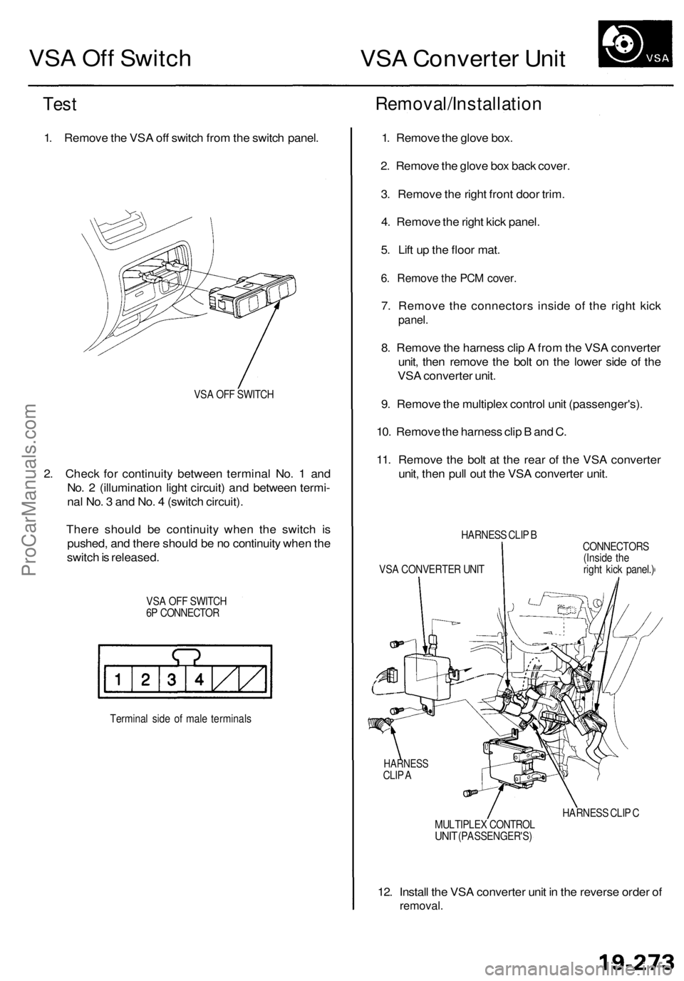
VSA Off Switch
VSA Converter Unit
Test
1. Remove the VSA off switch from the switch panel.
VSA OFF SWITCH
2. Check for continuity between terminal No. 1 and
No. 2 (illumination light circuit) and between termi-
nal No. 3 and No. 4 (switch circuit).
There should be continuity when the switch is
pushed, and there should be no continuity when the
switch is released.
VSA OFF SWITCH
6P CONNECTOR
Terminal side of male terminals
Removal/Installation
1. Remove the glove box.
2. Remove the glove box back cover.
3. Remove the right front door trim.
4. Remove the right kick panel.
5. Lift up the floor mat.
6. Remove the PCM cover.
7. Remove the connectors inside of the right kick
panel.
8. Remove the harness clip A from the VSA converter
unit, then remove the bolt on the lower side of the
VSA converter unit.
9. Remove the multiplex control unit (passenger's).
10. Remove the harness clip B and C.
11. Remove the bolt at the rear of the VSA converter
unit, then pull out the VSA converter unit.
HARNESS CLIP B
VSA CONVERTER UNIT
CONNECTORS
(Inside the
right kick panel.)
HARNESS
CLIP A
HARNESS CLIP C
MULTIPLEX CONTROL
UNIT
(PASSENGER'S)
12. Install the VSA converter unit in the reverse order of
removal.ProCarManuals.com
Page 1358 of 1954
Trunk Tri m
Remova l
CAUTION :
Put o n glove s t o protec t you r hands .
When pryin g wit h a flat-ti p screwdriver , wra p it wit h protectiv e tap e to preven t damage .
NOTE : Tak e car e no t t o ben d o r scratc h th e tri m an d panels .
Clip location s Scre
w locations , 2
TRUN K SID E
BOX
TRUN KHOOK
RIGH T TRUN K
SID E TRI M NOTE
: D o no t pus h th e
inne r cli p in to o far .
CLI P
REA R TRI M
PANE L
CD CHANGE R
COVER(for som e models )
LEFT TRUN K
SID E TRI M
TRUN K FRON T
TRI M
Installatio n is th e revers e o f th e remova l procedure .
NOTE:
If necessary , replac e an y damage d clips .
T o instal l th e F clips , pul l th e inne r cli p up , instal l
th e clip , the n pus h th e inne r cli p unti l it' s flush .
SPAR E TIR ELID
UPPE RTRIM
ProCarManuals.com
Page 1368 of 1954
Glove box :
1 . Remov e th e dashboar d lowe r cover .
HOOK S
DASHBOAR D LOWE R
COVER
2. Remov e th e glov e bo x sto p fro m eac h side .
Bolt locations , 2
5 x 0. 8 m m9 N- m (0. 9 kgf-m ,7 Ibf-ft )
TRUN K LI D
OPENE R MAI N
SWITC H
CONNECTO R
DAMPERCLIP
DAMPE RCLIP
GLOV E BO X
STOP S
GLOVE BO X
3. Detac h th e dampe r cli p whil e holdin g th e glov e box ,
an d disconnec t th e connector .
4 . Remov e th e bolts , the n remov e th e glov e box . 5
. Remov e th e glov e bo x bac k cover .
Clip locations , 4
GLOV E BO X
BAC K COVE R
6. Installatio n is th e revers e o f th e remova l procedure .
Passenger' s dashboar d panel :
1. Remov e th e sid e ai r vent .
2 . Carefull y detac h th e clips , the n pul l ou t th e passen -
ger' s dashboar d panel .
PASSENGER' SDASHBOARD PANE L
3. Installatio n i s th e revers e o f th e remova l procedure .
CLIPS
Clip locations , 3
Detac
h th e
connector .
Scre
w locations , 3
Cli p locations , 3
ProCarManuals.com
Page 1380 of 1954

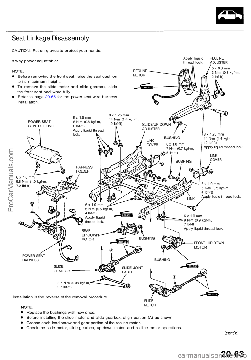
Seat Linkag e Disassembl y
CAUTION: Pu t o n glove s to protec t you r hands .
8-wa y powe r adjustable :
NOTE:
Before removin g th e fron t seat , rais e th e sea t cushio n
t o it s maximu m height .
T o remov e th e slid e moto r an d slid e gearbox , slid e
th e fron t sea t backwar d fully .
Refe r t o pag e 20-6 5 fo r th e powe r sea t wir e harnes s
installation .
POWER SEA TCONTRO L UNI T
Appl y liqui d RECLIN E
threa d lock . ADJUSTE R
RECLIN E
MOTO R
5 x 0. 8 m m3 N- m (0. 3 kgf-m ,
2 Ibf-ft )
8 x 1.2 5 mm14 N- m (1. 4 kgf-m ,
1 0 Ibf-ft )
Apply liqui d threa d lock .
6 x 1. 0 m m9.8 N- m (1. 0 kgf-m ,
7. 2 Ibf-ft )6 x 1. 0 m m5 N- m (0. 5 kgf-m ,
4 Ibf-ft )
Apply liqui d threa d lock .
POWE R SEA T
HARNES S
SLIDE
GEARBO X
3.7 N- m (0.3 8 kgf-m ,
2. 7 Ibf-ft )
Installatio n is th e revers e o f th e remova l procedure .SLIDE
MOTO R
NOTE:
Replac e th e bushing s wit h ne w ones .
Befor e installin g th e slid e moto r an d slid e gearbox , alig n portio n (A) a s shown .
Greas e eac h lea d scre w an d gea r portio n o f th e reclin e motor .
Chec k th e slid e motor , slid e gearbox , up-dow n motor , an d reclin e moto r operations .
SLIDE JOIN TCABLE
BUSHIN G
FRONT UP-DOW NMOTOR
6 x 1. 0 m m9 N- m (0. 9 kgf-m ,
7 Ibf-ft )
Apply liqui d threa d lock .
BUSHIN G
LINK LIN
K
COVE RBUSHIN G
6 x 1. 0 m m7 N- m (0. 7 kgf-m ,
5 Ibf-ft )
BUSHIN GLINKCOVE R
SLIDE/UP-DOW NADJUSTER
6 x 1. 0 m m8 N- m (0. 8 kgf-m ,
6 Ibf-ft )
Apply liqui d threa dlock.
8 x 1.2 5 m m14 N- m (1. 4 kgf-m ,
1 0 Ibf-ft )
HARNES SHOLDER
6 x 1. 0 m m5 N- m (0. 5 kgf-m ,
4 Ibf-ft )
Apply liqui dthrea d lock .
REARUP-DOW NMOTOR
ProCarManuals.com
Page 1560 of 1954
Trunk Ligh t Tes t
1. Pr y th e trunk light len s of f fro m th e housing .
Glove Bo x Ligh t Tes t
1. Ope n th e glov e box , an d disconnec t th e 2 P
connector .
NOTE : I f necessary , remov e th e glov e box .
BUL B (3. 4 W )
2. Chec k fo r continuit y betwee n th e terminal s i n eac h
switc h positio n accordin g t o th e table .
2 . Pr y ou t th e ligh t assembly .
3 . Disconnec t th e 2 P connecto r fro m th e housing .
4 . Mak e sur e th e bulb , an d chec k fo r continuit y
betwee n th e No . 1 an d No . 2 terminals .
LENS BUL
B
(5 W )
HOUSIN G
2P CONNECTO R
ProCarManuals.com
Page 1934 of 1954
6. Reconnect the airbag connector(s):
Front Passenger's Airbag:
• Connect the front passenger's airbag connector to
the SRS main harness connector, then install the
glove box.
Driver's Side:
• Connect the driver's airbag 2P connector to the cable
reel 2P connector, then install the access panel on the
steering wheel.
'96 - 98 Models
7. Reconnect the battery positive cable, then connect
the negative cable.
8. After installing the airbag, confirm proper system
operation:
• Turn the ignition switch ON (II); the SRS indica-
tor light should come on for about 6 seconds and
then go off.
• Make sure horn button works.
• Take a test drive, and make sure the cruise con-
trol switches work.
9. Enter the anti-theft code for the radio, then enter the
customer's radio station presets.
'99 - 01 ModelsProCarManuals.com