1996 ACURA RL KA9 wheel
[x] Cancel search: wheelPage 25 of 1954

VSA Modulator-Contro l Uni t
Removal/Installatio n
NOTE:
• D o no t spil l brak e flui d o n th e vehicle ; i t ma y damag e th e paint ; i f brak e flui d doe s contac t th e paint , was h i t of f imme -
diatel y wit h water .
• Tak e car e no t t o damag e o r defor m th e brak e line s durin g remova l an d installation .
• T o preven t th e brak e flui d fro m flowing , plu g an d cove r th e hos e end s an d joint s wit h a sho p towe l o r equivalen t material .
Remova l
1. Disconnec t th e pressur e senso r 3 P connector .
2 . Pul l th e lockin g leve r o f th e VS A contro l uni t 42 P connec -
to r up , the n disconnec t th e connector .
3 . Disconnec t th e si x brak e lines .
4 . Remov e th e tw o 8 m m nuts .
5 . Remov e th e VS A modulator-contro l unit .
Installatio n
1 . Instal l th e VS A modulator-contro l unit , the n tighte n th e
two 8 m m nuts .
2. Alig n th e connectin g surface s o f th e VS A contro l uni t 42 P
connector .
3 . Pus h th e lockin g leve r o f th e VS A contro l uni t 42 P con -
necto r dow n unti l yo u hea r a click .
4 . Connec t th e pressur e senso r 3 P connector .
5 . Connec t th e si x brak e lines .
6 . D o th e steerin g angl e senso r neutra l memorizatio n pro -
cedur e (se e pag e 19-8 ).
7 . Blee d th e precharg e brak e lin e (se e pag e 19-10 ).
8 . Blee d th e brak e system , startin g wit h th e fron t wheels .
9 . Star t th e engine , an d chec k tha t th e AB S an d VS A indica -
tor s g o off .
10 . Test-driv e th e vehicle , an d chec k tha t th e AB S an d VS A
indicator s d o no t com e on .
ProCarManuals.com
Page 198 of 1954

Electrical Troubleshootin g
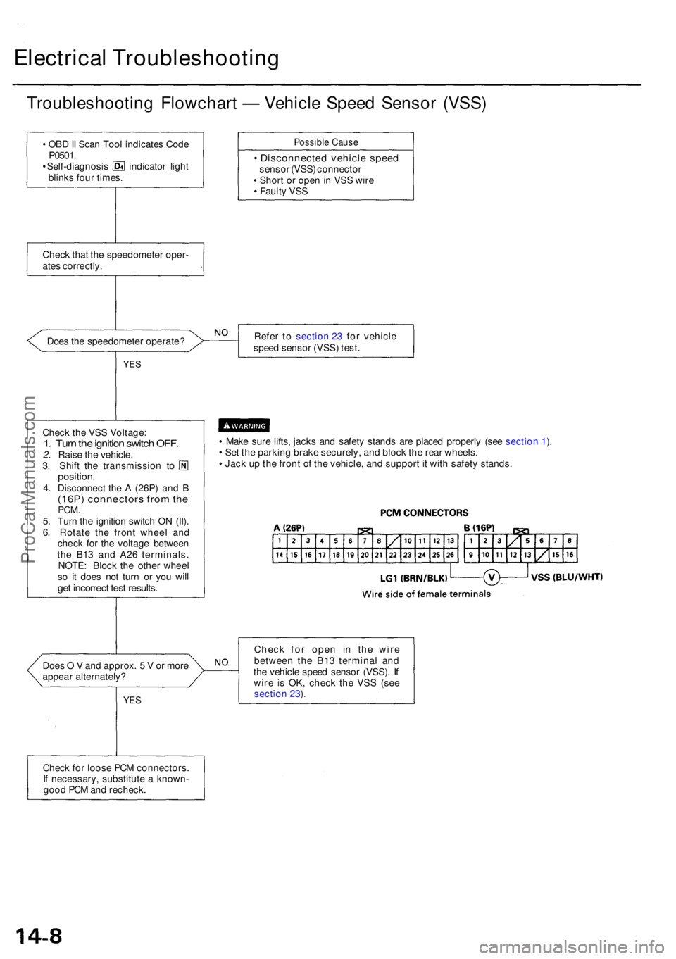
Troubleshooting Flowchar t — Vehicl e Spee d Senso r (VSS )
• OB D II Sca n Too l indicate s Cod e
P0501 .
• Self-diagnosi s indicato r ligh t
blink s fou r times .
Possibl e Caus e
• Disconnecte d vehicl e spee dsenso r (VSS ) connecto r
• Shor t o r ope n in VS S wir e
• Fault y VS S
Chec k tha t th e speedomete r oper -
ate s correctly .
Doe s th e speedomete r operate ? Refe
r t o
section 23 fo r vehicl e
spee d senso r (VSS ) test .
YES
• Mak e sur e lifts , jack s an d safet y stand s ar e place d properl y (se e section 1).
• Se t th e parkin g brak e securely , an d bloc k th e rea r wheels .
• Jac k u p th e fron t o f th e vehicle , an d suppor t i t wit h safet y stands .
Doe s O V and approx . 5 V or mor e
appea r alternately ?
YES
Chec k fo r ope n i n th e wir e
betwee n th e B1 3 termina l an d
th e vehicl e spee d senso r (VSS) . I f
wir e i s OK , chec k th e VS S (se e
section 23).
Chec k fo r loos e PC M connectors .
I f necessary , substitut e a known -
goo d PC M an d recheck .
Chec
k th e VS S Voltage :
1. Tur n th e ignitio n switc h OFF .2. Rais e th e vehicle .
3 . Shif t th e transmissio n t o
position .4. Disconnec t th e A (26P ) an d B(16P ) connector s fro m th ePCM .5. Tur n th e ignitio n switc h O N (II) .
6 . Rotat e th e fron t whee l an d
chec k fo r th e voltag e betwee n
th e B1 3 an d A2 6 terminals .
NOTE : Bloc k th e othe r whee l
s o i t doe s no t tur n o r yo u wil l
get incorrec t tes t results .
ProCarManuals.com
Page 239 of 1954

Navigation System
System Description (cont'd)
Overview
The Acura Navigation System is a highly-sophisticated, hybrid locating system that uses satellites and a map database to
show you where you are and to help guide you to a desired destination.
The navigation system receives signals from the Global Positioning System (GPS), a network of 24 satellites in orbit
around the earth. By receiving signals from serveral of these satellites, the navigation system can determine the latitude,
longitude, and elevation of the vehicle. In addition, signals from the system's yaw rate sensor and the PCM (vehicle
speed pulse) enable the system to keep track of the vehicle's direction and speed of travel.
This hybrid system has advantages over a system that is either entirely self-contained or one that relies totally on the
GPS. For example, the self-contained portion of the system can keep track of vehicle position even when satellite signals
cannot be received. When the navigation system is on, the GPS can keep track of the vehicle position even when the vehi-
cle is transported by ferry.
The navigation system applies all this location, direction, and speed information to the maps and calculates a route to the
destination entered. As you drive to that destination, the system provides both visual and audio guidance.
This navigation system also has voice recognition that allows voice control of most of the navigation functions. The TALK
and BACK buttons on the steering wheel activate the voice control.
The illumination signal is used for two purposes. The display unit uses the signal to light up the hard buttons surrounding
the display. In addition the signal is used by the navigation unit to automatically switch from the "Day" to "Night" display
mode when the headlights are on. This automatic switching occurs only if the "Display" setting in setup screen 1 is set to
"AUTO". If the headlights are on and the customer has the dash light brightness control to "full bright," then this overrides
the "Night" mode.
The use of the audio speakers follows a hierarchy. The highest priority is the OnStar voice, followed by the navigation voice,
and finally the radio/CD. The audio unit enforces this hierarchy. The GA-Net bus is used to pass commands to mute the speak-
ers, and to disable the voice control system. Prior systems used dedicated wires to accomplish this function.
• If On-Star is in use, the audio unit passes a command on the GA-Net bus to the navigation unit to disable the voice control
system. The navigation unit then ignores the voice control switch, and temporarily ceases voice route guidance prompts.
• When the navigation system issues route guidance, the navigation unit uses the GA-Net bus to tell the audio unit to mute just
the front speakers. When the voice control system is being used (the TALK/BACK buttons), the navigation unit uses the GA-
Net bus to tell the audio unit to mute all speakers.ProCarManuals.com
Page 275 of 1954

Navigation System
System Diagnosis Mode (cont'd)
GPS Offset Time
This screen is for factory use only. It allows adjustment
of the GPS time. This display updates in real time.
• "GPS Time" is the time as received from the GPS
satellites. It is in Greenwich Mean Time (GMT).
• "System Time" is the internal time used by the navi-
gation unit to calculate your position on the map.
It is also in Greenwich Mean Time (GMT).
• "Display Time" is the time shown on Setup screen 2
"Adjust Time Zone/Clock", and reflects any changes
due to daylight savings time or time adjustments
entered by the customer.
• Date, Hour, Minute, and "Set" buttons should not be
used.
Mic Level
This diagnostic allows you to independently test the
microphone and the TALK and BACK buttons on the
steering wheel (voice control switch). The microphone
and voice control switch are used to activate the voice
control system. The microphone is located near the map
light in the ceiling. It is directional, and works best if the
voice is coming from the drivers seat.
• Press the TALK button on the steering wheel, and in a
normal voice say "testing". The TALK indicator on
the screen should momentarily become green, and
the text "Now Recording..." should appear in yellow.
In addition, the Mic Level indicator should move at
least to the 6th bar. If the Talk indicator on the screen
does not briefly become green, then check the wiring
from the steering wheel talk button to the navigation
unit. If there is no "Mic Level" movement when you
speak, then you should check the wire running from
the microphone to the control unit.
• Press the BACK button on the steering wheel. This
should cause the Cancel indicator on the screen to
momentarily become green. If it does not briefly
change to green, then check the wiring from the
steering wheel BACK button to the navigation unit.ProCarManuals.com
Page 289 of 1954

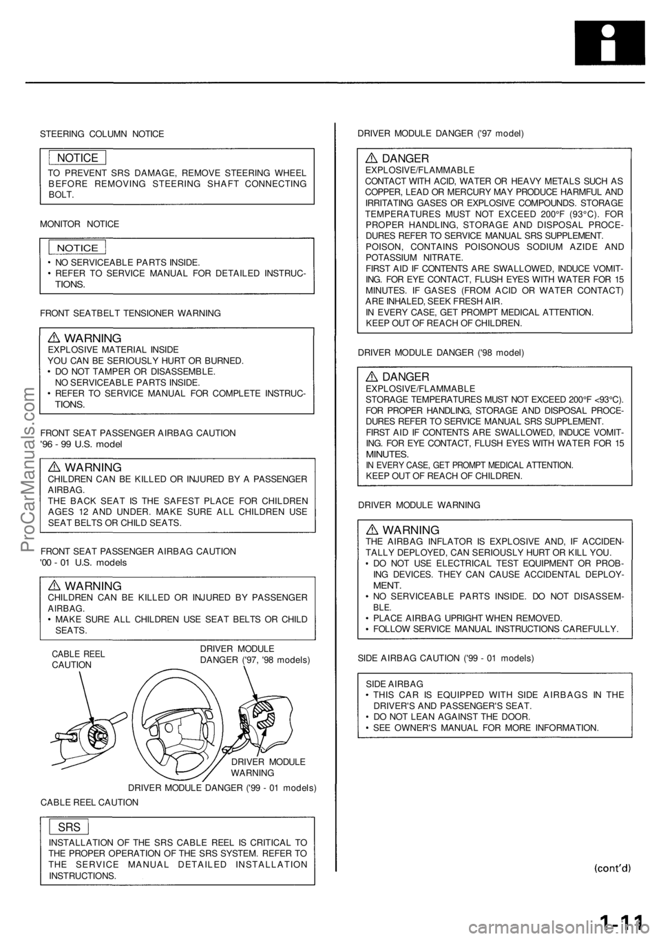
STEERING COLUMN NOTICE
TO PREVENT SRS DAMAGE, REMOVE STEERING WHEEL
BEFORE REMOVING STEERING SHAFT CONNECTING
BOLT.
MONITOR NOTICE
NOTICE
NO SERVICEABLE PARTS INSIDE.
REFER TO SERVICE MANUAL FOR DETAILED INSTRUC-
TIONS.
FRONT SEATBELT TENSIONER WARNING
WARNING
EXPLOSIVE MATERIAL INSIDE
YOU CAN BE SERIOUSLY HURT OR BURNED.
DO NOT TAMPER OR DISASSEMBLE.
NO SERVICEABLE PARTS INSIDE.
REFER TO SERVICE MANUAL FOR COMPLETE INSTRUC-
TIONS.
FRONT SEAT PASSENGER AIRBAG CAUTION
'96 - 99 U.S. model
WARNING
CHILDREN CAN BE KILLED OR INJURED BY A PASSENGER
AIRBAG.
THE BACK SEAT IS THE SAFEST PLACE FOR CHILDREN
AGES 12 AND UNDER. MAKE SURE ALL CHILDREN USE
SEAT BELTS OR CHILD SEATS.
FRONT SEAT PASSENGER AIRBAG CAUTION
'00 - 01 U.S. models
WARNING
CHILDREN CAN BE KILLED OR INJURED BY PASSENGER
AIRBAG.
MAKE SURE ALL CHILDREN USE SEAT BELTS OR CHILD
SEATS.
CABLE REEL
CAUTION
DRIVER MODULE
DANGER ('97, '98 models)
DRIVER MODULE
WARNING
DRIVER MODULE DANGER ('99 - 01 models)
CABLE REEL CAUTION
INSTALLATION OF THE SRS CABLE REEL IS CRITICAL TO
THE PROPER OPERATION OF THE SRS SYSTEM. REFER TO
THE SERVICE MANUAL DETAILED INSTALLATION
INSTRUCTIONS.
DRIVER MODULE DANGER ('97 model)
DANGER
EXPLOSIVE/FLAMMABLE
CONTACT WITH ACID, WATER OR HEAVY METALS SUCH AS
COPPER, LEAD OR MERCURY MAY PRODUCE HARMFUL AND
IRRITATING GASES OR EXPLOSIVE COMPOUNDS. STORAGE
TEMPERATURES MUST NOT EXCEED 200°F (93°C). FOR
PROPER HANDLING, STORAGE AND DISPOSAL PROCE-
DURES REFER TO SERVICE MANUAL SRS SUPPLEMENT.
POISON, CONTAINS POISONOUS SODIUM AZIDE AND
POTASSIUM NITRATE.
FIRST AID IF CONTENTS ARE SWALLOWED, INDUCE VOMIT-
ING. FOR EYE CONTACT, FLUSH EYES WITH WATER FOR 15
MINUTES. IF GASES (FROM ACID OR WATER CONTACT)
ARE INHALED, SEEK FRESH AIR.
IN EVERY CASE, GET PROMPT MEDICAL ATTENTION.
KEEP OUT OF REACH OF CHILDREN.
DRIVER MODULE DANGER ('98 model)
DANGER
EXPLOSIVE/FLAMMABLE
STORAGE TEMPERATURES MUST NOT EXCEED 200°F <93°C).
FOR PROPER HANDLING, STORAGE AND DISPOSAL PROCE-
DURES REFER TO SERVICE MANUAL SRS SUPPLEMENT.
FIRST AID IF CONTENTS ARE SWALLOWED, INDUCE VOMIT-
ING. FOR EYE CONTACT, FLUSH EYES WITH WATER FOR 15
MINUTES.
IN EVERY CASE, GET PROMPT MEDICAL ATTENTION.
KEEP OUT OF REACH OF CHILDREN.
DRIVER MODULE WARNING
WARNING
THE AIRBAG INFLATOR IS EXPLOSIVE AND, IF ACCIDEN-
TALLY DEPLOYED, CAN SERIOUSLY HURT OR KILL YOU.
DO NOT USE ELECTRICAL TEST EQUIPMENT OR PROB-
ING DEVICES. THEY CAN CAUSE ACCIDENTAL DEPLOY-
MENT.
NO SERVICEABLE PARTS INSIDE. DO NOT DISASSEM-
BLE.
PLACE AIRBAG UPRIGHT WHEN REMOVED.
FOLLOW SERVICE MANUAL INSTRUCTIONS CAREFULLY.
SIDE AIRBAG CAUTION ('99 - 01 models)
SIDE AIRBAG
THIS CAR IS EQUIPPED WITH SIDE AIRBAGS IN THE
DRIVER'S AND PASSENGER'S SEAT.
DO NOT LEAN AGAINST THE DOOR.
SEE OWNER'S MANUAL FOR MORE INFORMATION.
SRS
NOTICEProCarManuals.com
Page 297 of 1954

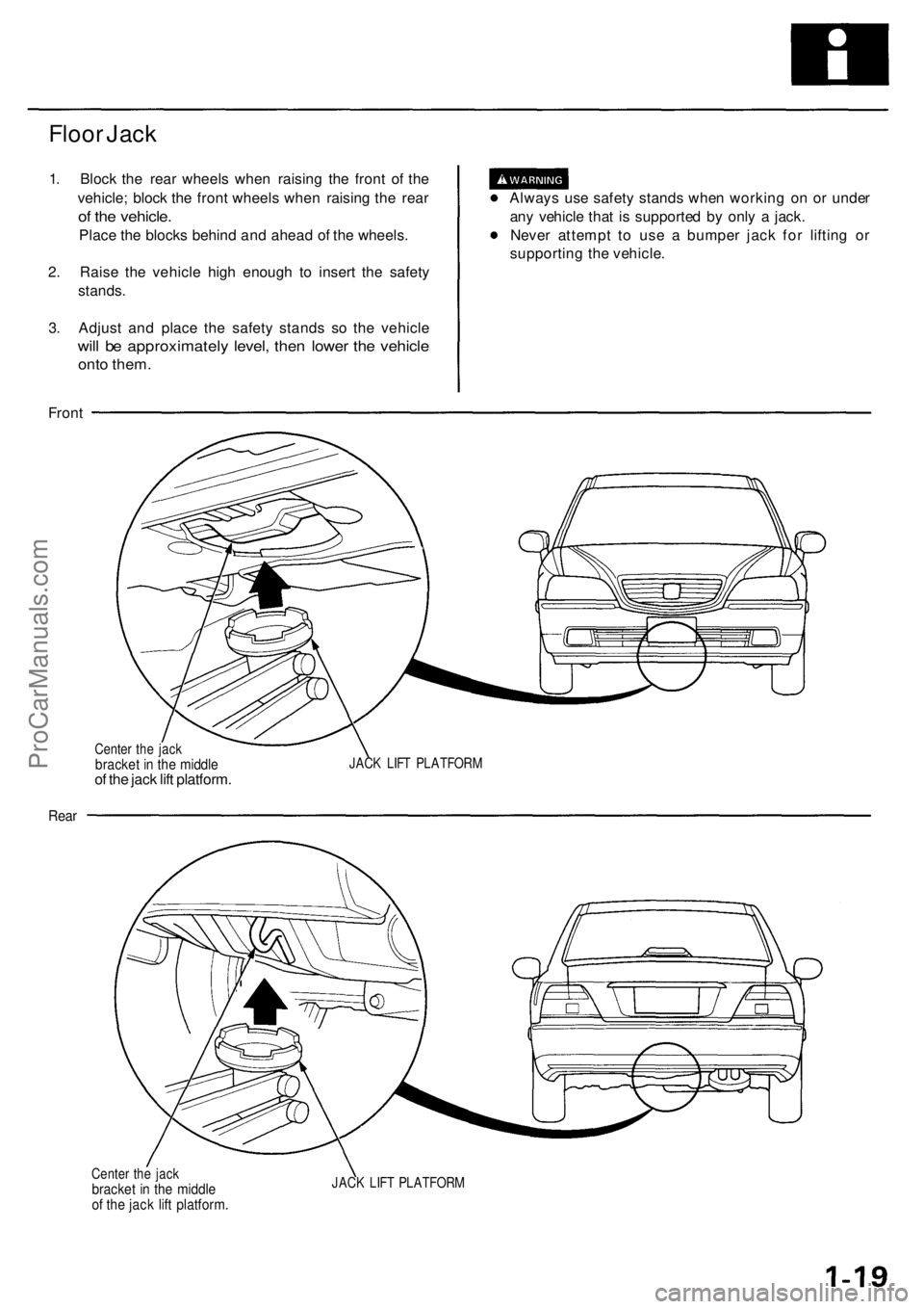
Floor Jack
1. Block the rear wheels when raising the front of the
vehicle; block the front wheels when raising the rear
of the vehicle.
Place the blocks behind and ahead of the wheels.
2. Raise the vehicle high enough to insert the safety
stands.
3. Adjust and place the safety stands so the vehicle
will be approximately level, then lower the vehicle
onto them.
Always use safety stands when working on or under
any vehicle that is supported by only a jack.
Never attempt to use a bumper jack for lifting or
supporting the vehicle.
Front
Center the jack
bracket in the middle
of the jack lift platform.
JACK LIFT PLATFORM
Rear
Center the jack
bracket in the middle
of the jack lift platform.
JACK LIFT PLATFORMProCarManuals.com
Page 298 of 1954

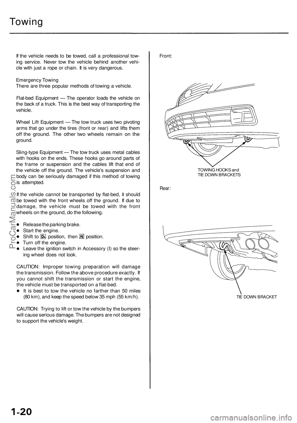
Towing
If th e vehicl e need s t o b e towed , cal l a professiona l tow -
in g service . Neve r to w th e vehicl e behin d anothe r vehi -
cl e wit h jus t a rop e o r chain . I t i s ver y dangerous .
Emergenc y Towin g
Ther e ar e thre e popula r method s o f towin g a vehicle .
Flat-be d Equipmen t — Th e operato r load s th e vehicl e o n
th e bac k o f a truck . Thi s is th e bes t wa y o f transportin g th e
vehicle .
Whee l Lif t Equipmen t — Th e to w truc k use s tw o pivotin g
arm s tha t g o unde r th e tire s (fron t o r rear ) an d lift s the m
off th e ground . Th e othe r tw o wheel s remai n o n th e
ground .
Sling-typ e Equipmen t — Th e to w truc k use s meta l cable s
wit h hook s o n th e ends . Thes e hook s g o aroun d part s o f
th e fram e o r suspensio n an d th e cable s lif t tha t en d o f
th e vehicl e of f th e ground . Th e vehicle' s suspensio n an d
bod y ca n b e seriousl y damage d i f thi s metho d o f towin g
i s attempted .
I f th e vehicl e canno t b e transporte d b y flat-bed , i t shoul d
b e towe d wit h th e fron t wheel s of f th e ground . I f du e t o
damage , th e vehicl e mus t b e towe d wit h th e fron t
wheel s o n th e ground , d o th e following .
Release th e parkin g brake .
Star t th e engine .
Shift t o position , the n position .
Tur n of f th e engine .
Leav e th e ignitio n switc h in Accessor y (I ) s o th e steer -
in g whee l doe s no t look .
CAUTION : Imprope r towin g preparatio n wil l damag e
th e transmission . Follo w th e abov e procedur e exactly . I f
yo u canno t shif t th e transmissio n o r star t th e engine ,
th e vehicl e mus t b e transporte d o n a flat-bed .
I t i s bes t t o to w th e vehicl e n o farthe r tha n 5 0 mile s
(8 0 km) , an d kee p th e spee d belo w 35 mp h (5 5 km/h) .
CAUTION : Tryin g to lif t o r to w th e vehicl e b y th e bumper s
wil l caus e seriou s damage . Th e bumper s ar e no t designe d
t o suppor t th e vehicle' s weight .
Front:
TOWIN G HOOK S an dTIE DOW N BRACKET S
Rear:
TIE DOW N BRACKE T
ProCarManuals.com
Page 309 of 1954

Lubrication Points
For the details of lubrication points and types of lubricants to be applied, refer to the Illustrated Index and various work
procedures (such as Assembly/Reassembly, Replacement, Overhaul, Installation, etc.) contained in each section.
No.
1
2
3
4
5
6
7
8
9
10
11
12
13
14
15
16
17
18
19
20
21
22
LUBRICATION POINTS
Engine
Transmission
Brake line (Includes ABS line)
Power steering gearbox
Steering boots
Throttle cable end
Steering ball joints
Shift lever (Automatic transmission)
Pedal linkage
Intermediate shaft
Brake master cylinder pushrod
Fuel
fill
lid
Battery terminals
Trunk hinges and latch
Door hinges upper and lower
Door opening detents
Hood hinges and hood latch
Brake line joints (Front and rear wheelhouse)
Caliper Piston boot, caliper
Pins and boots
Power steering system
Differential
A/C compressor
API SERVICE LABEL API CERTIFICATION SEAL
LUBRICANT
API Service Grade: Use SJ "Energy Conserving" grade oil.
The oil container may also display the API Certification
seal shown below. Make sure it says "For Gasoline
Engines."
SAE Viscosity: See chart below.
Honda ATF-Z1 (ATF)*1
Genuine Honda DOT3 brake fluid*2
Steering grease P/N 08733 - B070E
Multi-purpose grease
Honda White Lithium Grease
Rust preventive
Silicone grease
Genuine Honda power steering fluid*3
Hypoid gear Oil API GL4 or GL5
Viscosity:
at above -18°C (0°F): SAE 90
at less than -18°C (0°F): SAE 80W-90
Compressor oil:
DENSO: ND-OIL8 (P/N) 38897 - PR7 - A01 AH or 38899 -
PR7-A01)
(For Refrigerant: HFC-134a (R-134a))
Recommended engine oil
viscosity for ambient
temperature ranges
*1: Always use Honda ATF-Z1 (ATF). Using a non-Honda ATF can affect shift quality.
*2: Always use Genuine Honda DOT3 Brake Fluid. Using a non-Honda brake fluid can cause corrosion and decrease the
life of the system.
*3: Always use Genuine Honda Power Steering Fluid. Using any other type of power steering fluid or automatic transmis-
sion fluid can cause increased wear and poor steering in cold weather.ProCarManuals.com