1996 ACURA RL KA9 wheel
[x] Cancel search: wheelPage 722 of 1954
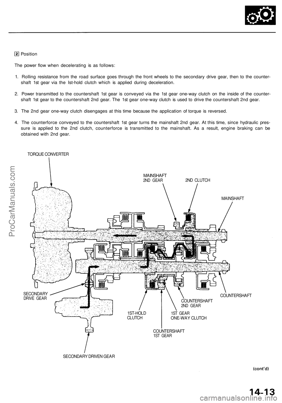
Position
The power flow when decelerating is as follows:
1. Rolling resistance from the road surface goes through the front wheels to the secondary drive gear, then to the counter-
shaft 1st gear via the Ist-hold clutch which is applied during deceleration.
2. Power transmitted to the countershaft 1st gear is conveyed via the 1st gear one-way clutch on the inside of the counter-
shaft 1st gear to the countershaft 2nd gear. The 1st gear one-way clutch is used to drive the countershaft 2nd gear.
3. The 2nd gear one-way clutch disengages at this time because the application of torque is reversed.
4. The counterforce conveyed to the countershaft 1st gear turns the mainshaft 2nd gear. At this time, since hydraulic pres-
sure is applied to the 2nd clutch, counterforce is transmitted to the mainshaft. As a result, engine braking can be
obtained with 2nd gear.
TORQUE CONVERTER
MAINSHAFT
2ND GEAR
2ND CLUTCH
MAINSHAFT
SECONDARY
DRIVE GEAR
COUNTERSHAFT
1ST GEAR
ONE-WAY CLUTCH
COUNTERSHAFT
1ST GEAR
SECONDARY DRIVEN GEAR
1ST-HOLD
CLUTCH
COUNTERSHAFT
2ND GEARProCarManuals.com
Page 769 of 1954

Electrical Troubleshootin g
Troubleshooting Flowchar t — Vehicl e Spee d Senso r (VSS )
• OB D II Sca n Too l indicate s Cod eP1791 .• Self-diagnosi s indicato r ligh t
blink s fou r times .
Possibl e Caus e
• Disconnecte d vehicl e spee dsensor (VSS ) connecto r• Shor t o r ope n in VS S wir e
• Fault y VS S
Chec k tha t th e speedomete r oper -
ate s correctly .
Doe s th e speedomete r operate ? Refe
r t o sectio n 2 3 fo r vehicl e
spee d senso r (VSS ) test .
Chec k th e VS S Voltage :
1. Tur n th e ignitio n switc h OFF .2. Rais e th e vehicle .3. Shif t th e transmissio n t o
position .
4 . Disconnec t th e A (26P ) an d B
(16P ) connector s fro m th ePCM .5. Tur n th e ignitio n switc h O N (II) .
6 . Rotat e th e fron t whee l an d
chec k fo r th e voltag e betwee n
the B1 3 an d A2 6 terminals .NOTE: Bloc k th e othe r whee lso i t doe s no t tur n o r yo u wil lget incorrec t tes t results . •
Mak e sur e lifts , jack s an d safet y stand s ar e place d properl y (se e sectio n 1 ).
• Se t th e parkin g brak e securely , an d bloc k th e rea r wheels .
• Jac k u p th e fron t o f th e vehicle , an d suppor t i t wit h safet y stands .
Doe s 0 V and approx . 5 V or mor e
appea r alternately ? Chec
k fo r ope n i n th e wir e
betwee n th e B1 3 termina l an d
th e vehicl e spee d senso r (VSS) . I f
wir e i s OK , chec k th e VS S (se e
sectio n 23 ).
Chec k fo r loos e PC M connectors .
I f necessary , substitut e a known -
goo d PC M an d recheck . PC
M CONNECTOR S
Wir e sid e o f femal e terminal s
ProCarManuals.com
Page 799 of 1954

Transmission Rang e Switc h (A/ T Gea r Positio n Switch )
Test
Mak e sur e lifts , jacks , an d safet y stand s ar e place d properl y (se e sectio n 1 ).
1 . Rais e th e fron t o f th e vehicle , an d suppor t i t wit h safet y stand s (se e sectio n 1 ).
2 . Se t th e parkin g brake , an d bloc k bot h rea r wheel s securely .
3 . Pul l th e carpe t bac k t o expos e th e secondar y heate d oxyge n senso r (secondar y HO2S ) connector . Disconnec t th e con -
nector , the n pus h it ou t unde r th e vehicl e (se e pag e 14-90 ).
NOTE : Th e secondar y HO2 S connecto r i s unde r th e passenger' s seat .
4 . Remov e th e exhaus t pip e A bracket , the n remov e exhaus t pip e A .
5 . Remov e th e secondar y HO2 S harnes s cover , the n remov e th e thre e wa y catalyti c converter .
6 . Remov e th e hea t shields .
7 . Disconnec t th e transmissio n rang e switc h connector .
TRANSMISSIO N RANG ESWITCH CONNECTO R(10P)
Termina l sid e o f mal e terminal s
8. Chec k fo r continuit y betwee n th e termina l i n eac h switc h positio n accordin g t o th e tabl e below .
• Mov e th e shif t leve r bac k an d fort h withou t pushin g th e shif t leve r a t eac h switc h position , an d chec k fo r continuit y
withi n th e rang e o f it s fre e play .
• I f ther e i s n o continuit y withi n th e rang e o f fre e play , adjus t th e transmissio n rang e switch .
Neutral
Positio n Switc h
Transmissio
n Rang e Switc h
ProCarManuals.com
Page 800 of 1954
Replacement
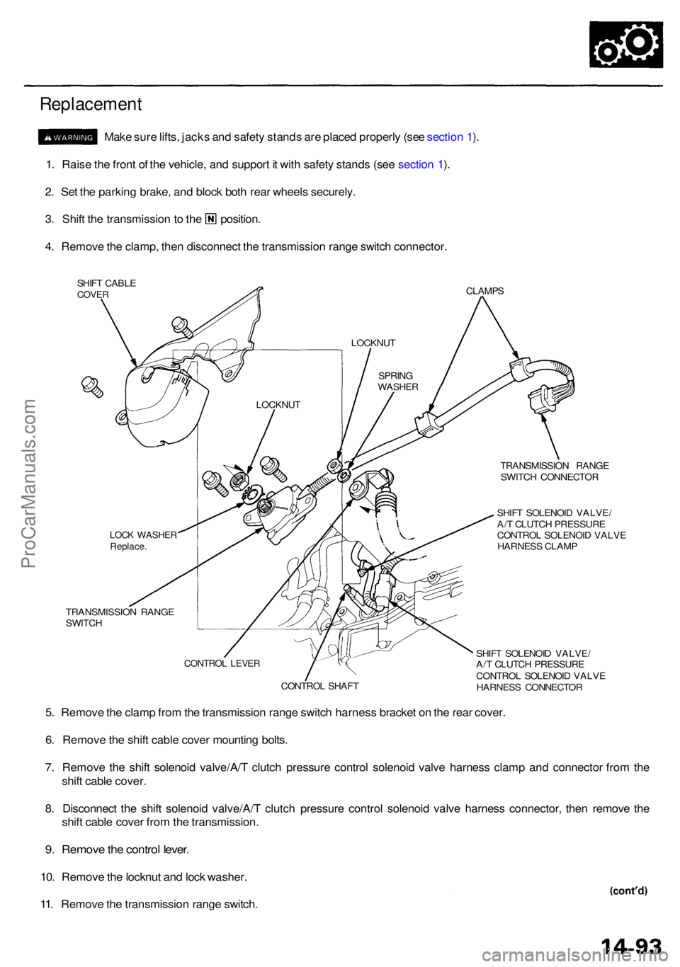
Make sur e lifts , jack s an d safet y stand s ar e place d properl y (se e sectio n 1 ).
1 . Rais e th e fron t o f th e vehicle , an d suppor t i t wit h safet y stand s (se e sectio n 1 ).
2 . Se t th e parkin g brake , an d bloc k bot h rea r wheel s securely .
3. Shif t th e transmissio n to th e position .
4 . Remov e th e clamp , the n disconnec t th e transmissio n rang e switc h connector .
SHIFT CABL ECOVERCLAMP S
TRANSMISSIO N RANG E
SWITC H CONNECTO R
SHIF T SOLENOI D VALVE /
A/ T CLUTC H PRESSUR E
CONTRO L SOLENOI D VALV E
HARNES S CLAM P
TRANSMISSIO N RANG E
SWITC H
SHIFT SOLENOI D VALVE /
A/ T CLUTC H PRESSUR E
CONTRO L SOLENOI D VALV E
HARNES S CONNECTO R
5. Remov e th e clam p fro m th e transmissio n rang e switc h harnes s bracke t o n th e rea r cover .
6 . Remov e th e shif t cabl e cove r mountin g bolts .
7 . Remov e th e shif t solenoi d valve/A/ T clutc h pressur e contro l solenoi d valv e harnes s clam p an d connecto r fro m th e
shif t cabl e cover .
8 . Disconnec t th e shif t solenoi d valve/A/ T clutc h pressur e contro l solenoi d valv e harnes s connector , the n remov e th e
shif t cabl e cove r fro m th e transmission .
9. Remov e th e contro l lever .
10. Remov e th e locknu t an d loc k washer .
11 . Remov e th e transmissio n rang e switch .
LOCKNU T
LOCK WASHE RReplace.
CONTRO L SHAF T
CONTRO L LEVE R
SPRIN G
WASHE R
LOCKNU
T
ProCarManuals.com
Page 810 of 1954
NOTES
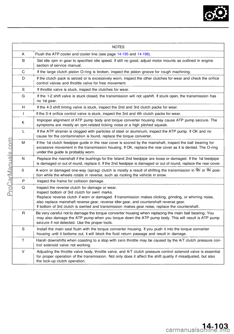
A Flus h th e AT P coole r an d coole r lin e (se e pag e 14-19 5 an d 14-196 ).
B Se t idl e rp m in gea r t o specifie d idl e speed . I f stil l n o good , adjus t moto r mount s a s outline d i n engin e
sectio n o f servic e manual .
C I f th e larg e clutc h pisto n O-rin g i s broken , inspec t th e pisto n groov e fo r roug h machining .
D I f th e clutc h pac k i s seize d o r i s excessivel y worn , inspec t th e othe r clutche s fo r wea r an d chec k th e orific e
contro l valve s an d throttl e valv e fo r fre e movement .
E I f throttl e valv e i s stuck , inspec t th e clutche s fo r wear .
G I f th e 1- 2 shif t valv e i s stuc k closed , th e transmissio n wil l no t upshift . I f stuc k open , th e transmissio n ha s
n o 1s t gear .
H I f th e 4- 3 shif t timin g valv e i s stuck , inspec t th e 2n d an d 3r d clutc h pack s fo r wear .
I I f th e 3- 4 orific e contro l valv e i s stuck , inspec t th e 3r d an d 4t h clutc h pack s fo r wear .
Imprope r alignmen t o f AT P pum p bod y an d torqu e converte r housin g ma y caus e AT P pum p seizure . Th e
symptom s ar e mostl y a n rpm-relate d tickin g nois e o r a hig h pitche d squeak .
L I f th e ATP straine r i s clogge d wit h particle s o f stee l o r aluminum , inspec t th e AT P pump . I f O K an d n o
caus e fo r th e contaminatio n i s found , replac e th e torqu e converter .
M I f th e 1s t clutc h feedpip e guid e i n th e rea r cove r i s score d b y th e mainshaft , inspec t th e bal l bearin g fo r
excessiv e movemen t i n th e transmissio n housing . I f OK , replac e th e rea r cove r a s i t i s dented . Th e O-rin g
under th e guid e is probabl y worn .
N Replac e th e mainshaf t i f th e bushing s fo r th e Islan d 2n d feedpip e ar e loos e o r damaged . I f th e 1s t feedpip e
i s damage d o r ou t o f round , replac e it . I f th e 2n d feedpip e is damage d o r ou t o f round , replac e th e rea r cover .
0 A worn o r damage d one-wa y (sprag ) clutc h i s mostl y a resul t o f shiftin g th e transmissio n in o r posi -
tio n whil e th e wheel s rotat e i n reverse , suc h a s rockin g th e vehicl e in snow .
P Inspec t th e fram e fo r collisio n damage .
Q Inspec t th e revers e clutc h fo r damag e o r wear .
Inspec t botto m o f 3r d clutc h fo r swir l marks .
Replac e revers e clutc h i f wor n o r damaged . I f transmissio n make s clicking , grinding , o r whirrin g noise ,
als o replac e mainshaf t revers e gear , revers e idle r gear , an d countershaf t revers e gear .
I f botto m o f 3r d clutc h i s swirle d an d transmissio n make s gea r noise , replac e th e countershaft .
R B e ver y carefu l no t t o damag e th e torqu e converte r housin g whe n replacin g th e mai n bal l bearing . Yo u
may als o damag e th e AT P pum p whe n yo u torqu e dow n th e ATP pum p body . Thi s wil l resul t i s AT P pum p
seizur e i f no t detected . Us e th e prope r tools .
S Instal l th e mai n sea l flus h wit h th e torqu e converte r housing . I f yo u pus h i t int o th e torqu e converte r
housin g unti l i t bottom s out , i t wil l bloc k th e flui d retur n passag e an d resul t i n damage .
T Hars h downshift s whe n coastin g t o a sto p wit h zer o throttl e ma y b e cause d b y th e A/ T clutc h pressur e con -
tro l solenoi d valv e no t working .
V Adjustin g th e throttl e valv e body , throttl e valve , an d A/ T clutc h pressur e contro l solenoi d valv e i s essentia l
fo r prope r operatio n o f th e transmission . No t onl y doe s i t affec t th e shif t qualit y i f misadjusted , bu t als o
th e lock-u p clutc h operation .
ProCarManuals.com
Page 811 of 1954

Road Tes t
NOTE : War m u p th e engin e to norma l operatin g temperatur e (th e radiato r fa n come s on) .
1. Appl y parkin g brak e an d bloc k th e wheels . Star t th e engine , the n shif t t o positio n whil e pressin g th e brak e pedal .
Pres s th e accelerato r peda l an d releas e it suddenly . Th e engin e shoul d no t stall .
2. Repea t th e sam e tes t i n position .
3. Test-driv e th e vehicl e o n th e fla t roa d in position . Chec k tha t th e shif t point s occu r a t th e approximat e speed s
shown o n th e nex t page . Als o chec k fo r abnorma l nois e an d clutc h slippage .
NOTE : Throttl e positio n senso r voltag e represent s th e throttl e opening .
a . Remov e th e PC M cove r t o expos e th e PC M fo r roa d testing ; refe r t o pag e 14-5 4 an d 14-55 .
b . Se t th e digita l multimete r t o chec k voltag e betwee n D 6 (+ ) termina l an d A2 6 (- ) termina l o f th e PC M fo r th e throttl e
positio n sensor .
NOTE : Refe r t o pag e 14-54 ; Ho w to us e th e Backprob e Set .
SRS component s ar e locate d in thi s area . Revie w th e SR S componen t locations , precautions , an d procedure s in th e SR S
(sectio n 24 ) befor e performin g repair s o r service .
PCM
D6 Termina l
DIGITAL MULTIMETE R(Commercially available )KS - AH M - 3 2 - 003 ,or equivalen t
BACKPROB E SE T07SAZ-001000A(two required )
BACKPROB EADAPTER
STACKIN G PATC H CORD S
A26 Termina l
PCM CONNECTOR S
ProCarManuals.com
Page 814 of 1954
Stall Speed
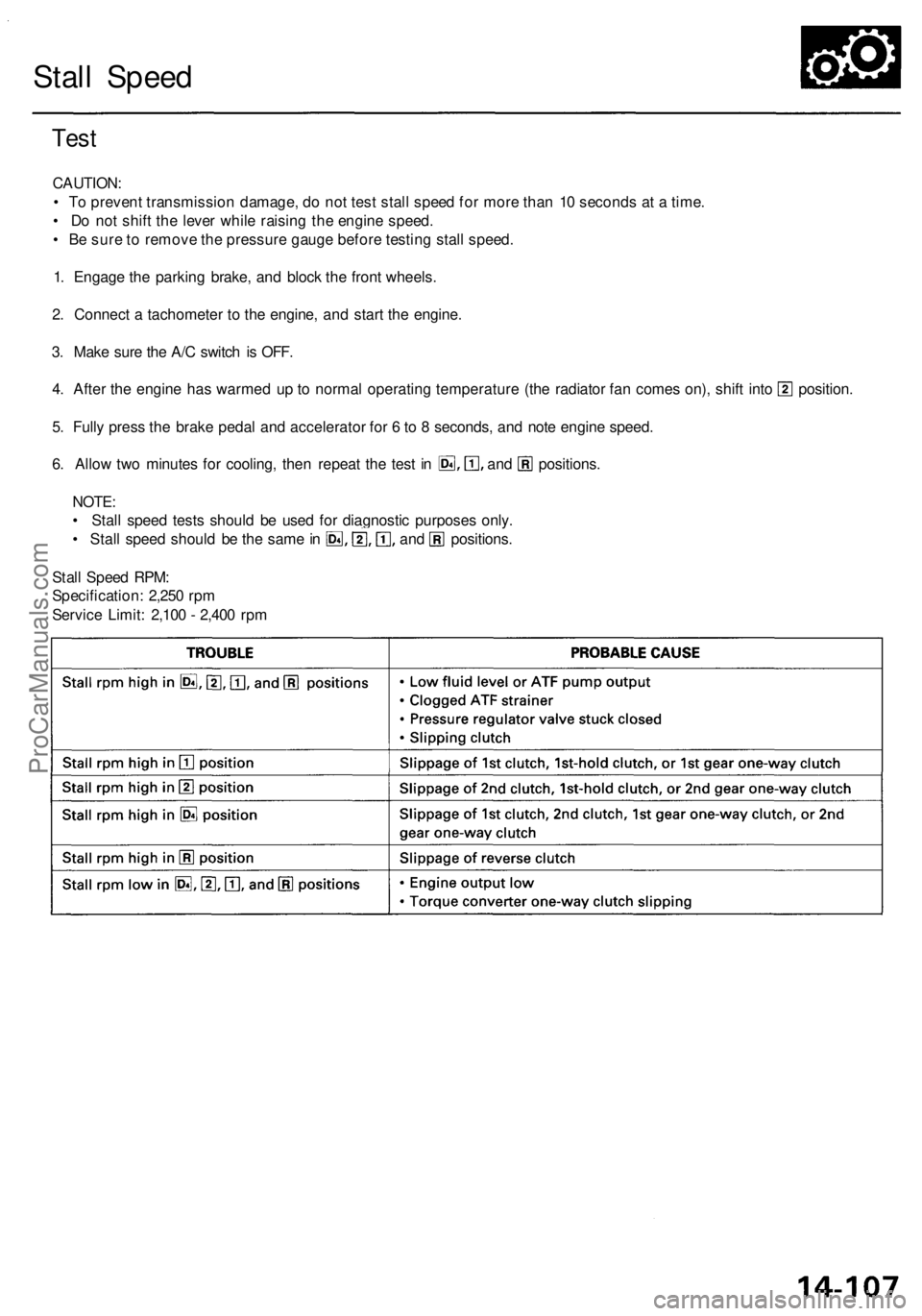
Test
CAUTION:
• To prevent transmission damage, do not test stall speed for more than 10 seconds at a time.
• Do not shift the lever while raising the engine speed.
• Be sure to remove the pressure gauge before testing stall speed.
1. Engage the parking brake, and block the front wheels.
2. Connect a tachometer to the engine, and start the engine.
3. Make sure the A/C switch is OFF.
4. After the engine has warmed up to normal operating temperature (the radiator fan comes on), shift into position.
5. Fully press the brake pedal and accelerator for 6 to 8 seconds, and note engine speed.
6. Allow two minutes for cooling, then repeat the test in and positions.
NOTE:
• Stall speed tests should be used for diagnostic purposes only.
• Stall speed should be the same in and positions.
Stall Speed RPM:
Specification: 2,250 rpm
Service Limit: 2,100 - 2,400 rpmProCarManuals.com
Page 816 of 1954
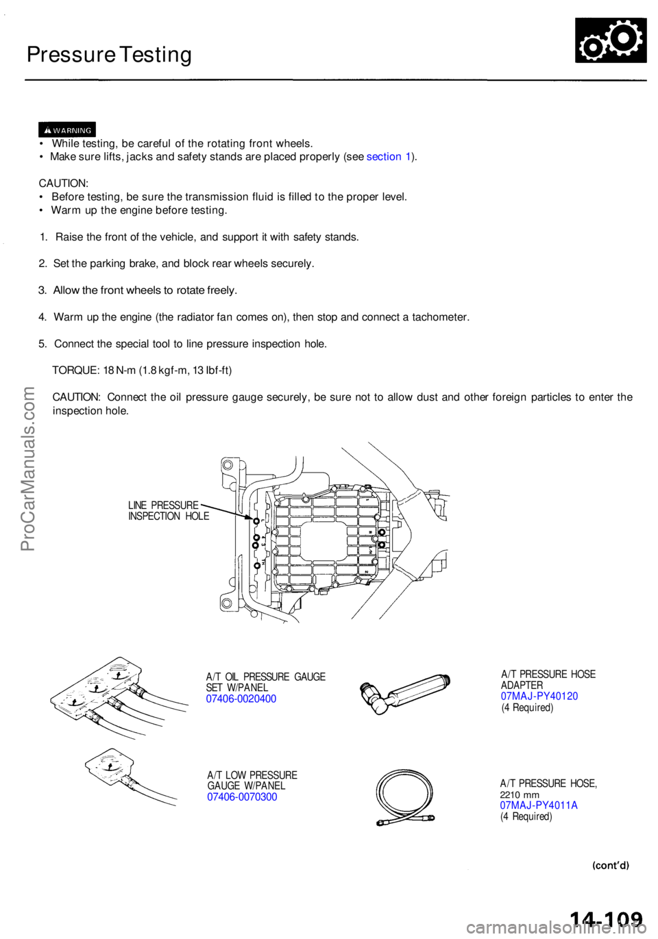
Pressure Testin g
• Whil e testing , b e carefu l o f th e rotatin g fron t wheels .
• Mak e sur e lifts , jack s an d safet y stand s ar e place d properl y (se e sectio n 1 ).
CAUTION :
• Befor e testing , b e sur e th e transmissio n flui d is fille d to th e prope r level .
• War m up th e engin e befor e testing .
1 . Rais e th e fron t o f th e vehicle , an d suppor t i t wit h safet y stands .
2 . Se t th e parkin g brake , an d bloc k rea r wheel s securely .
3. Allo w th e fron t wheel s to rotat e freely .
4. War m u p th e engin e (th e radiator fan come s on) , the n sto p an d connec t a tachometer .
5 . Connec t th e specia l too l t o lin e pressur e inspectio n hole .
TORQUE : 1 8 N- m (1. 8 kgf-m , 1 3 Ibf-ft )
CAUTION : Connec t th e oi l pressur e gaug e securely , b e sur e no t t o allo w dus t an d othe r foreig n particle s t o ente r th e
inspectio n hole .
LINE PRESSUR E
INSPECTIO N HOL E
A/ T OI L PRESSUR E GAUG E
SE T W/PANE L
07406-002040 0
A/T LO W PRESSUR E
GAUG E W/PANE L
07406-007030 0
A/T PRESSUR E HOS E
ADAPTE R
07MAJ-PY4012 0(4 Required )
A/ T PRESSUR E HOSE ,
2210 mm07MAJ-PY4011 A(4 Required )
ProCarManuals.com