Page 1029 of 1954
Wheel Runou t
1. Rais e th e vehicl e of f th e ground , an d support it wit h
safet y stand s in th e prope r location s (se e sectio n 1 ).
2 . Chec k fo r ben t o r deforme d wheels .
3 . Attac h th e dia l gaug e a s shown .
Axia l Runou t
Standard :
Aluminum Wheel : 0 - 0.7 m m (0 - 0.0 3 in )
Servic e Limit : 2. 0 m m (0.0 8 in )
Radia l Runou t
Standard :
Aluminu m Wheel : 0 - 0.7 m m (0 - 0.0 3 in )
Servic e Limit : 1. 5 m m (0.0 6 in )
4 . Measur e th e whee l runou t b y turnin g th e wheel .
5 . I f th e whee l runou t i s mor e tha n th e servic e limit ,
replac e th e wheel .
ProCarManuals.com
Page 1030 of 1954
Front Suspensio n
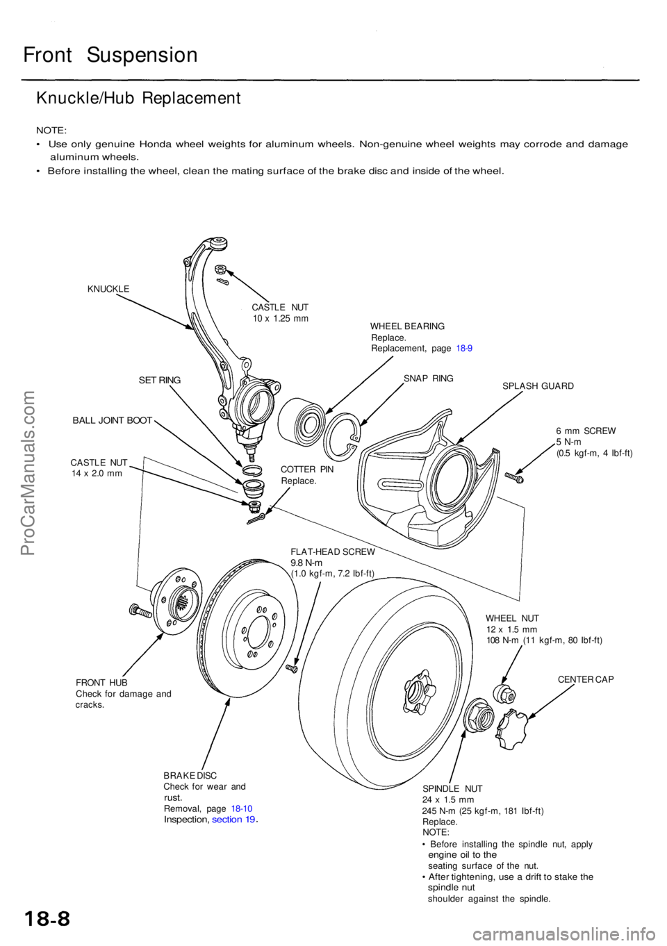
Knuckle/Hub Replacemen t
NOTE:
• Us e onl y genuin e Hond a whee l weight s fo r aluminu m wheels . Non-genuin e whee l weight s ma y corrod e an d damag e
aluminu m wheels .
• Befor e installin g th e wheel , clea n th e matin g surfac e o f th e brak e dis c an d insid e o f th e wheel .
KNUCKL E
WHEEL BEARIN G
Replace .
Replacement , pag e 18- 9
SPLASH GUAR D
BALL JOIN T BOO T
CASTL E NU T14 x 2. 0 m m
FRON T HU B
Chec k fo r damag e an d
cracks .
BRAKE DIS C
Chec k fo r wea r an d
rust .Removal , pag e 18-1 0Inspection , sectio n 1 9
6 m m SCRE W5 N- m(0.5 kgf-m , 4 Ibf-ft )
WHEE L NU T
12 x 1. 5 m m108 N- m (1 1 kgf-m , 8 0 Ibf-ft )
CENTE R CA P
SPINDL E NU T
24 x 1. 5 m m245 N- m (2 5 kgf-m , 18 1 Ibf-ft )
Replace .
NOTE :
• Befor e installin g th e spindl e nut , appl y
engine oi l t o th eseatin g surfac e o f th e nut .• Afte r tightening , us e a drif t t o stak e th espindl e nu tshoulde r agains t th e spindle .
FLAT-HEA
D SCRE W
9.8 N- m(1.0 kgf-m , 7. 2 Ibf-ft )
COTTE
R PI N
Replace .
SNAP RIN G
CASTL
E NU T
10 x 1.2 5 mm
SE T RIN G
ProCarManuals.com
Page 1031 of 1954
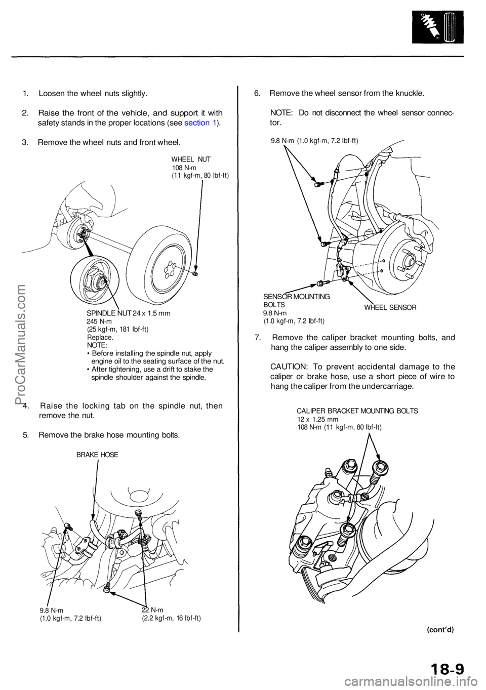
1. Loose n th e whee l nut s slightly .
2. Rais e th e fron t o f th e vehicle , an d suppor t i t wit h
safet y stand s in th e prope r location s (se e sectio n 1 ).
3 . Remov e th e whee l nut s an d fron t wheel .
WHEE L NU T108 N- m(11 kgf-m , 8 0 Ibf-ft )
SPINDL E NU T 2 4 x 1. 5 m m245 N- m(25 kgf-m , 18 1 Ibf-ft )Replace .NOTE:• Befor e installin g th e spindl e nut , appl y
engin e oi l t o th e seatin g surfac e o f th e nut .
• Afte r tightening , us e a drif t t o stak e th e
spindl e shoulde r agains t th e spindle .
4. Rais e th e lockin g ta b o n th e spindl e nut , the n
remov e th e nut .
5 . Remov e th e brak e hos e mountin g bolts .
BRAK E HOS E
9.8 N- m(1.0 kgf-m , 7. 2 Ibf-ft )22 N- m(2.2 kgf-m , 1 6 Ibf-ft )
6. Remov e th e whee l senso r fro m th e knuckle .
NOTE : D o no t disconnec t th e whee l senso r connec -
tor.
9.8 N- m (1. 0 kgf-m , 7. 2 Ibf-ft )
SENSO R MOUNTIN GBOLTS9.8 N- m(1.0 kgf-m , 7. 2 Ibf-ft )
WHEE L SENSO R
7. Remov e th e calipe r bracke t mountin g bolts , an d
han g th e calipe r assembl y t o on e side .
CAUTION : T o preven t accidenta l damag e t o th e
calipe r o r brak e hose , us e a shor t piec e o f wir e t o
han g th e calipe r fro m th e undercarriage .
CALIPER BRACKE T MOUNTIN G BOLT S12 x 1.2 5 mm108 N- m (1 1 kgf-m , 8 0 Ibf-ft )
ProCarManuals.com
Page 1034 of 1954
Front Suspensio n
Knuckle/Hu b Replacemen t (cont'd )
27. Remov e th e splas h guard .
6 m m SCRE W SPLAS
H GUAR D
28. Remov e th e sna p rin g fro m th e knuckle .
KNUCKL E
SNAP RIN G
29. Pres s th e whee l bearin g ou t o f th e knuckl e usin g th e
specia l tool s an d a press .
DRIVE R07749-001000 0 Pres s
ATTACHMENT ,72 x 75 m m07746-001060 0
WHEELBEARIN G
HUB DIS/ASSEMBL Y BAS E
07GAF-SD4070 0
30. Remov e th e outboar d bearin g inne r rac e fro m th e
hu b usin g th e specia l tool s an d a commerciall y
availabl e bearin g separator .
PressHUB DIS/ASSEMBL Y TOO L
07GAF-SE0010 0
INNE R
RACE
BEARIN G SEPARATOR ,0-4 1/ 2 in .(Commerciall y available )
ProCarManuals.com
Page 1035 of 1954
NOTE: Was h th e knuckl e an d hu b thoroughl y i n
hig h flas h poin t solven t befor e reassembly .
31 . Pres s a ne w whee l bearin g int o th e knuckl e usin g
th e ol d bearing , plat e an d a press .
PressPLAT E
OLD BEARIN G
KNUCKL E
SUPPOR TBASE07965-6920201
WHEE L BEARIN G
DRIVER ATTACHMEN T78 x 90 m m07GAD-SD4010 1
32. Instal l th e sna p rin g securel y in th e knuckl e groove .
KNUCKL E
SNAP RIN G
33. Instal l th e splas h guard , an d tighte n th e screws .
6 m m SCRE W
4. 9 N- m (0. 5 kgf-m , 4 Ibf-ft )
SPLAS H
GUARD
34. Plac e th e fron t hu b i n th e specia l too l fixture , the n
se t th e knuckl e i n position , an d appl y downwar d
pressure usin g th e specia l tool s an d a press .
Press
ATTACHMENT ,42 x 47 m m07746-001030 0
FRONTHUB
ATTACHMENT ,72 x 7 5 m m07746-001060 0WHEEL BEARIN G
SUPPOR TBASE07965-SD9010 0
35. Instal l i n revers e orde r o f removal .
ProCarManuals.com
Page 1041 of 1954
Rear Suspensio n
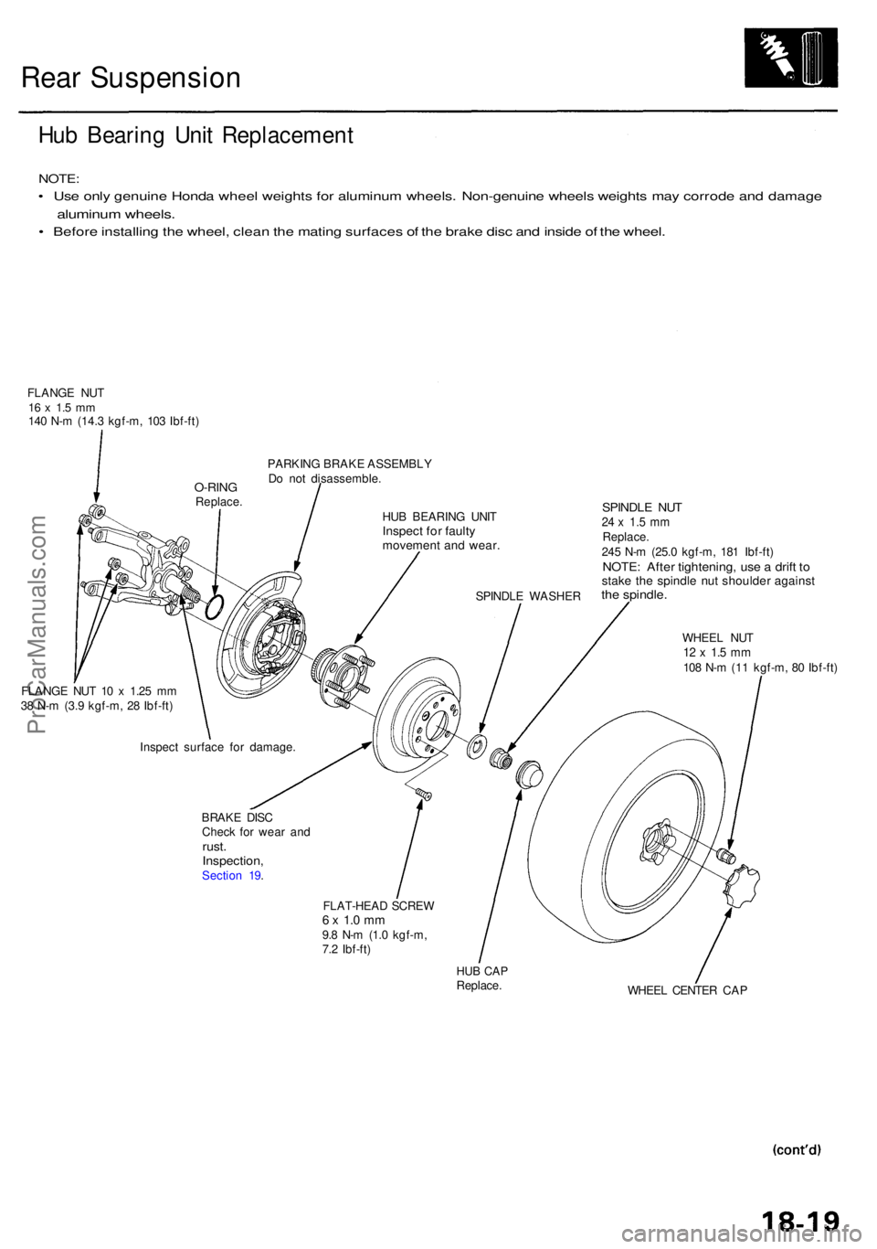
Hub Bearin g Uni t Replacemen t
NOTE:
• Us e onl y genuin e Hond a whee l weight s fo r aluminu m wheels . Non-genuin e wheel s weight s ma y corrod e an d damag e
aluminum wheels .
• Befor e installin g th e wheel , clea n th e matin g surface s o f th e brak e dis c an d insid e o f th e wheel .
FLANG E NU T16 x 1. 5 m m140 N- m (14. 3 kgf-m , 10 3 Ibf-ft )
PARKING BRAK E ASSEMBL Y
D o no t disassemble .
HU B BEARIN G UNI T
Inspec t fo r fault ymovemen t an d wear .
SPINDL E WASHE R
SPINDLE NU T24 x 1. 5 m mReplace .245 N- m (25. 0 kgf-m , 18 1 Ibf-ft )NOTE : Afte r tightening , us e a drif t t ostak e th e spindl e nu t shoulde r agains tthe spindle .
WHEEL NU T12 x 1. 5 m m108 N- m (1 1 kgf-m , 8 0 Ibf-ft )
FLANG E NU T 1 0 x 1.2 5 m m
3 8 N- m (3. 9 kgf-m , 2 8 Ibf-ft )
BRAKE DIS C
Chec k fo r wea r an d
rust .Inspection ,Section 19 .
FLAT-HEAD SCRE W
6 x 1. 0 m m9.8 N- m (1. 0 kgf-m ,
7. 2 Ibf-ft )
HUB CA PReplace .
WHEEL CENTE R CA P
Inspec
t surfac e fo r damage .
O-RINGReplace .
ProCarManuals.com
Page 1042 of 1954
Rear Suspensio n
Hub Bearin g Uni t Replacemen t (cont'd )
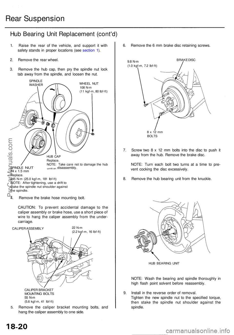
1. Rais e th e rea r o f th e vehicle , an d suppor t i t wit h
safet y stand s i n prope r location s (se e sectio n 1 ).
2 . Remov e th e rea r wheel .
3 . Remov e th e hu b cap , the n pr y th e spindl e nu t loc k
ta b awa y fro m th e spindle , an d loose n th e nut .
SPINDL EWASHE R
HUB CA PReplace .NOTE: Tak e car e no t t o damag e th e hu b
SPINDL E NUT uni t on disassembly .24 x 1. 5 m mReplace .
24 5 N- m (25. 0 kgf-m , 18 1 Ibf-ft )
NOTE : Afte r tightening , us e a drif t t ostak e th e spindl e nu t shoulde r agains tthe spindle .
4. Remov e th e brak e hos e mountin g bolt .
CAUTION : T o preven t accidenta l damag e t o th e
calipe r assembl y o r brak e hose , us e a shor t piec e o f
wir e t o han g th e calipe r assembl y fro m th e under -
carriage .
CALIPER ASSEMBL Y22 N- m(2.2 kgf-m , 1 6 Ibf-ft )
5.
CALIPE R BRACKE TMOUNTING BOLT S55 N- m(5.6 kgf-m , 4 1 Ibf-ft )
Remov e th e calipe r bracke t mountin g bolts , an d
hang th e calipe r assembl y to on e side .
6. Remov e th e 6 m m brak e dis c retainin g screws .
9.8 N- m(1.0 kgf-m , 7. 2 Ibf-ft ) BRAK
E DIS C
8 x 1 2 m mBOLT S
7. Scre w tw o 8 x 1 2 m m bolt s int o th e dis c t o pus h i t
awa y fro m th e hub . Remov e th e brak e disc .
NOTE : Tur n eac h bol t tw o turn s a t a tim e t o pre -
ven t cockin g th e dis c excessively .
8 . Remov e th e hu b bearin g uni t fro m th e knuckle .
9.
HU B BEARIN G UNI T
NOTE : Was h th e bearin g an d spindl e thoroughl y i n
hig h flas h poin t solven t befor e reassembly .
Instal l i n th e revers e orde r o f removal .
Tighte n th e ne w spindl e nu t t o th e specifie d torque ,
the n stak e th e spindl e nu t shoulde r agains t th e
spindle .
WHEEL NU T108 N- m(11 kgf-m , 8 0 Ibf-ft )
ProCarManuals.com
Page 1052 of 1954
Inspection an d Adjustmen t
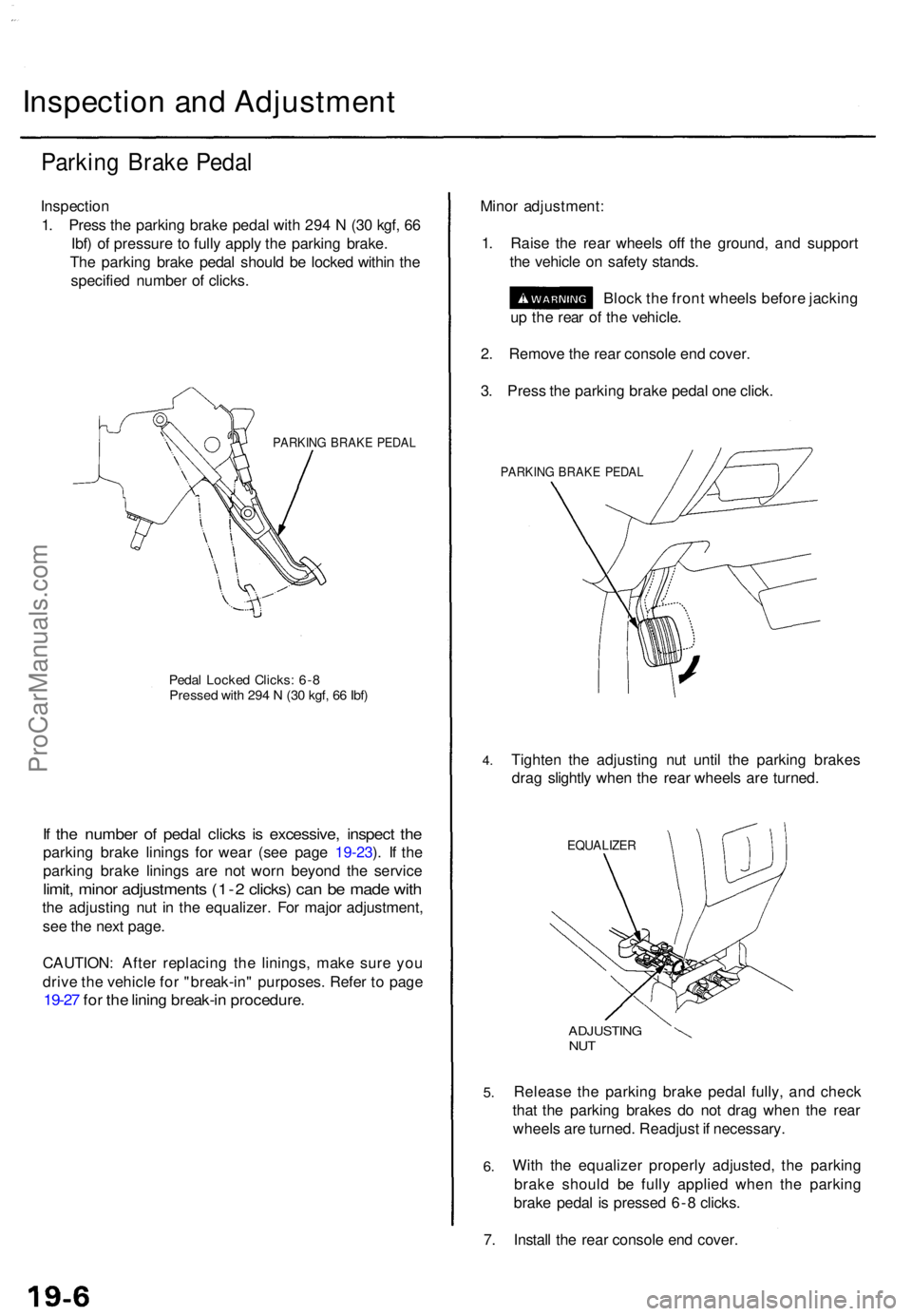
Parking Brak e Peda l
Inspectio n
1 . Pres s th e parkin g brak e peda l wit h 29 4 N (3 0 kgf , 6 6
Ibf ) o f pressur e to full y appl y th e parkin g brake .
Th e parkin g brak e peda l shoul d b e locke d withi n th e
specifie d numbe r o f clicks .
PARKIN G BRAK E PEDA L
Pedal Locke d Clicks : 6- 8Presse d wit h 29 4 N (3 0 kgf , 6 6 Ibf )
If th e numbe r o f peda l click s i s excessive , inspec t th e
parkin g brak e lining s fo r wea r (se e pag e 19-23 ). I f th e
parkin g brak e lining s ar e no t wor n beyon d th e servic e
limit, mino r adjustment s (1- 2 clicks ) ca n b e mad e wit h
the adjustin g nu t i n th e equalizer . Fo r majo r adjustment ,
se e th e nex t page .
CAUTION : Afte r replacin g th e linings , mak e sur e yo u
driv e th e vehicl e fo r "break-in " purposes . Refe r t o pag e
19-27 fo r th e linin g break-i n procedure .
Minor adjustment :
1 . Rais e th e rea r wheel s of f th e ground , an d suppor t
th e vehicl e o n safet y stands .
Bloc k th e fron t wheel s befor e jackin g
u p th e rea r o f th e vehicle .
2 . Remov e th e rea r consol e en d cover .
3 . Pres s th e parkin g brak e peda l on e click .
PARKIN G BRAK E PEDA L
4.Tighte n th e adjustin g nu t unti l th e parkin g brake s
dra g slightl y whe n th e rea r wheel s ar e turned .
EQUALIZE R
5.
6.
ADJUSTIN GNUT
Releas e th e parkin g brak e peda l fully , an d chec k
tha t th e parkin g brake s d o no t dra g whe n th e rea r
wheel s ar e turned . Readjus t i f necessary .
Wit h th e equalize r properl y adjusted , th e parkin g
brak e shoul d b e full y applie d whe n th e parkin g
brak e peda l i s presse d 6- 8 clicks .
7 . Instal l th e rea r consol e en d cover .
ProCarManuals.com