1996 ACURA RL KA9 wheel
[x] Cancel search: wheelPage 1084 of 1954
Troubleshooting Precautions
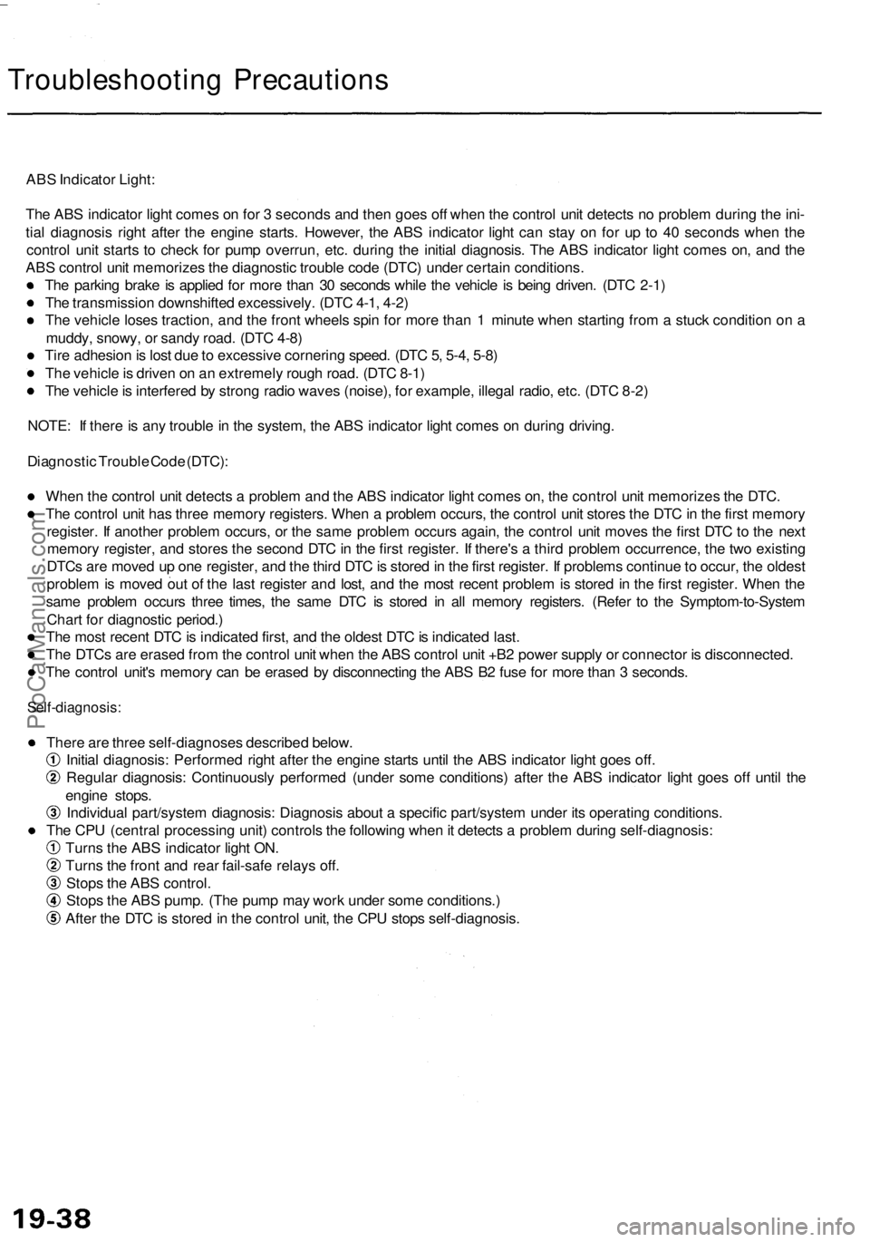
ABS Indicator Light:
The ABS indicator light comes on for 3 seconds and then goes off when the control unit detects no problem during the ini-
tial diagnosis right after the engine starts. However, the ABS indicator light can stay on for up to 40 seconds when the
control unit starts to check for pump overrun, etc. during the initial diagnosis. The ABS indicator light comes on, and the
ABS control unit memorizes the diagnostic trouble code (DTC) under certain conditions.
The parking brake is applied for more than 30 seconds while the vehicle is being driven. (DTC 2-1)
The transmission downshifted excessively. (DTC 4-1, 4-2)
The vehicle loses traction, and the front wheels spin for more than 1 minute when starting from a stuck condition on a
muddy, snowy, or sandy road. (DTC 4-8)
Tire adhesion is lost due to excessive cornering speed. (DTC 5, 5-4, 5-8)
The vehicle is driven on an extremely rough road. (DTC 8-1)
The vehicle is interfered by strong radio waves (noise), for example, illegal radio, etc. (DTC 8-2)
NOTE: If there is any trouble in the system, the ABS indicator light comes on during driving.
Diagnostic Trouble Code (DTC):
When the control unit detects a problem and the ABS indicator light comes on, the control unit memorizes the DTC.
The control unit has three memory registers. When a problem occurs, the control unit stores the DTC in the first memory
register. If another problem occurs, or the same problem occurs again, the control unit moves the first DTC to the next
memory register, and stores the second DTC in the first register. If there's a third problem occurrence, the two existing
DTCs are moved up one register, and the third DTC is stored in the first register. If problems continue to occur, the oldest
problem is moved out of the last register and lost, and the most recent problem is stored in the first register. When the
same problem occurs three times, the same DTC is stored in all memory registers. (Refer to the Symptom-to-System
Chart for diagnostic period.)
The most recent DTC is indicated first, and the oldest DTC is indicated last.
The DTCs are erased from the control unit when the ABS control unit +B2 power supply or connector is disconnected.
The control unit's memory can be erased by disconnecting the ABS B2 fuse for more than 3 seconds.
Self-diagnosis:
There are three self-diagnoses described below.
Initial diagnosis: Performed right after the engine starts until the ABS indicator light goes off.
Regular diagnosis: Continuously performed (under some conditions) after the ABS indicator light goes off until the
engine stops.
Individual part/system diagnosis: Diagnosis about a specific part/system under its operating conditions.
The CPU (central processing unit) controls the following when it detects a problem during self-diagnosis:
Turns the ABS indicator light ON.
Turns the front and rear fail-safe relays off.
Stops the ABS control.
Stops the ABS pump. (The pump may work under some conditions.)
After the DTC is stored in the control unit, the CPU stops self-diagnosis.ProCarManuals.com
Page 1111 of 1954
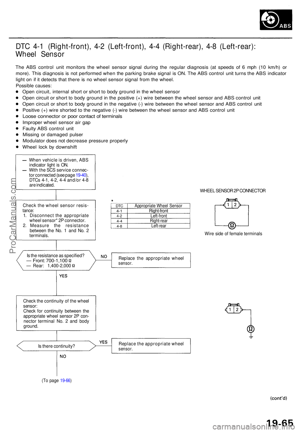
DTC 4- 1 (Right-front) , 4- 2 (Left-front) , 4- 4 (Right-rear) , 4- 8 (Left-rear) :
Whee l Senso r
The AB S contro l uni t monitor s th e whee l senso r signa l durin g th e regula r diagnosi s (a t speed s o f 6 mp h (1 0 km/h ) o r
more) . Thi s diagnosi s i s no t performe d whe n th e parkin g brak e signa l i s ON . Th e AB S contro l uni t turn s th e AB S indicator
ligh t o n i f i t detect s tha t ther e i s n o whee l senso r signa l fro m th e wheel .
Possibl e causes :
Open circuit , interna l shor t o r shor t t o bod y groun d in th e whee l senso r
Ope n circui t o r shor t t o bod y groun d in th e positiv e (+ ) wir e betwee n th e whee l senso r an d AB S contro l uni t
Ope n circui t o r shor t t o bod y groun d i n th e negativ e (- ) wir e betwee n th e whee l senso r an d AB S contro l uni t
Positiv e (+ ) wir e shorte d t o th e negativ e (- ) wir e betwee n th e whee l senso r an d AB S contro l uni t
Loos e connecto r o r poo r contac t o f terminal s
Improper whee l senso r ai r ga p
Fault y AB S contro l uni t
Missin g o r damage d pulse r
Modulato r doe s no t decreas e pressur e properl y
Whee l loc k b y downshif t
Is th e resistanc e a s specified ?— Front : 700-1,10 0— Rear : 1,400-2,00 0
Chec k th e continuit y o f th e whee l
sensor :Check fo r continuit y betwee n th e
appropriat e whee l senso r 2 P con -
necto r termina l No . 2 an d bod y
ground .
Is ther e continuity ?
(To pag e 19-66 )
WHEE L SENSO R 2P CONNECTO R
DTC4-14- 24- 44-8
Appropriat e Whee l Senso rRight-fron tLeft-frontRight-rea rLeft-rear
Wire sid e o f femal e terminal s
Replac e th e appropriat e whee l
sensor .
Replac e th e appropriat e whee lsensor .
When vehicl e is driven , ABS
indicato r ligh t i s ON .
Wit h th e SC S servic e connec -
to r connecte d (se e pag e 19-40 ),
DTC s 4-1 , 4-2 , 4- 4 and/o r 4- 8
ar e indicated .
Chec k th e whee l senso r resis -
tance :
1 . Disconnec t th e appropriat e
whee l sensor * 2 P connector .
2 . Measur e th e resistanc e
betwee n th e No . 1 an d No . 2
terminals .
ProCarManuals.com
Page 1113 of 1954
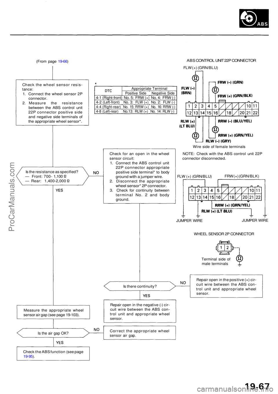
(From pag e 19-66 ) AB S CONTRO L UNI T 22 P CONNECTO R
FLW (+ ) (GRN/BLU )
Chec k th e whee l senso r resis -
tance:1. Connec t th e whee l senso r 2 Pconnector .2. Measur e th e resistanc e
betwee n th e AB S contro l uni t
22 P connecto r positiv e sid e
an d negativ e sid e terminal s o f
th e appropriat e whee l sensor* .
I s th e resistanc e a s specified ?
— Front : 700 - 1,10 0— Rear : 1,400-2,00 0 Chec
k fo r a n ope n i n th e whee l
senso r circuit :1. Connec t th e AB S contro l uni t22P connecto r appropriat epositive sid e terminal * t o bod ygroun d wit h a jumpe r wire .2. Disconnec t th e appropriat ewheel sensor * 2 P connector .3. Chec k fo r continuit y betwee ntermina l No . 2 an d bod yground . Wir
e sid e o f femal e terminal s
NOTE : Chec k wit h th e AB S contro l uni t 22 P
connecto r disconnected .
FL W (+ ) (GRN/BLU )FR
W (+ ) (GRN/BLK )
WHEE L SENSO R 2 P CONNECTO R
Termina l sid e o f
mal e terminal s
I s ther e continuity ? Repai
r ope n in th e positiv e (+ ) cir -
cui t wir e betwee n th e AB S con -
tro l uni t an d appropriat e whee l
sensor .
Repair ope n in th e negativ e (- ) cir -
cui t wir e betwee n th e AB S con -
tro l uni t an d appropriat e whee l
sensor .
Correc t th e appropriat e whee lsensor ai r gap .
Measur e th e appropriat e whee l
senso r ai r ga p (se e pag e 19-103) .
Is th e ai r ga p OK ?
Chec k th e AB S functio n (se e pag e19-95 ).
JUMPE R WIR E JUMPE
R WIR E
Appropriat e Termina lPositive Sid e Negativ e Sid e4-1 (Right-front ) No . 5 : FR W (+ ) No . 4 : FR W (-)4- 2 (Left-front ) No . 3 : FL W (+ ) No . 2 : FL W (-)4- 4 (Right-rear ) No . 15 : RR W (+ ) No . 16 : RR W (-)4- 8 (Left-rear ) No.13 : RL W (+ ) No . 14 : RL W (-)
ProCarManuals.com
Page 1114 of 1954
Troubleshooting
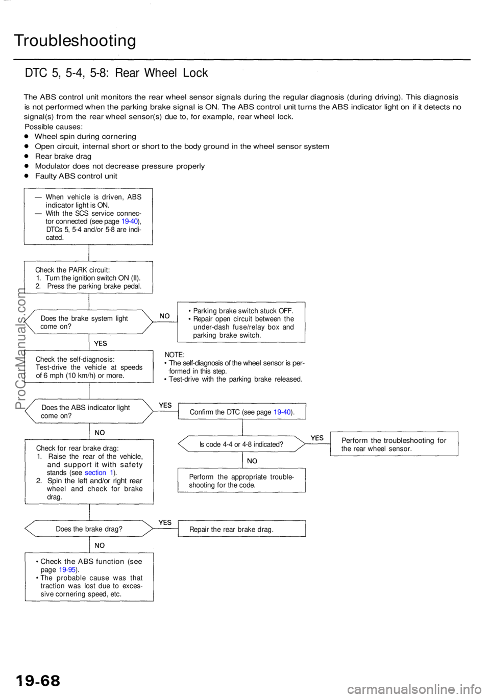
DTC 5 , 5-4 , 5-8 : Rea r Whee l Loc k
The AB S contro l uni t monitor s th e rea r whee l senso r signal s durin g th e regula r diagnosi s (durin g driving) . Thi s diagnosi s
is no t performe d whe n th e parkin g brak e signa l i s ON . Th e AB S contro l uni t turn s th e AB S indicato r ligh t o n if i t detect s n o
signal(s ) fro m th e rea r whee l sensor(s ) du e to , fo r example , rea r whee l lock .
Possibl e causes :
Wheel spi n durin g cornerin g
Open circuit , interna l shor t o r shor t t o th e bod y groun d in th e whee l senso r syste m
Rear brak e dra g
Modulato r doe s no t decreas e pressur e properl y
Faulty AB S contro l uni t
— Whe n vehicl e i s driven , ABSindicato r ligh t i s ON .— Wit h th e SC S servic e connec -tor connecte d (se e pag e 19-40 ),DTC s 5 , 5- 4 and/o r 5- 8 ar e indi -
cated .
Chec k th e PAR K circuit :
1. Tur n th e ignitio n switc h O N (II) .2. Pres s th e parking brake pedal .
Doe s th e brak e syste m ligh t
com e on ? Parkin
g brak e switc h stuc k OFF .
Repai r ope n circui t betwee n th e
under-das h fuse/rela y bo x an d
parkin g brak e switch .
NOTE:The self-diagnosi s o f th e whee l senso r i s per -forme d i n thi s step .
Test-driv e wit h th e parkin g brak e released .
Does th e AB S indicato r ligh tcom e on ?
Chec k fo r rea r brak e drag :
1 . Rais e th e rea r o f th e vehicle ,
and suppor t i t wit h safet ystands (se e sectio n 1 ).2 . Spi n th e lef t and/o r righ t rea rwhee l an d chec k fo r brak e
drag . I
s cod e 4- 4 o r 4- 8 indicated ?
Perform th e troubleshootin g fo rthe rea r whee l sensor .
Perfor m th e appropriat e trouble -
shootin g fo r th e code .
Doe s th e brak e drag ?
Repair th e rea r brak e drag .
Check th e AB S functio n (se epage 19-95 ).
Th e probabl e caus e wa s tha t
tractio n wa s los t du e t o exces -
siv e cornerin g speed , etc .
Chec
k th e self-diagnosis :
Test-driv e th e vehicl e a t speed s
of 6 mp h (1 0 km/h ) o r more .
Confir m th e DT C (se e pag e 19-40 ).
ProCarManuals.com
Page 1139 of 1954
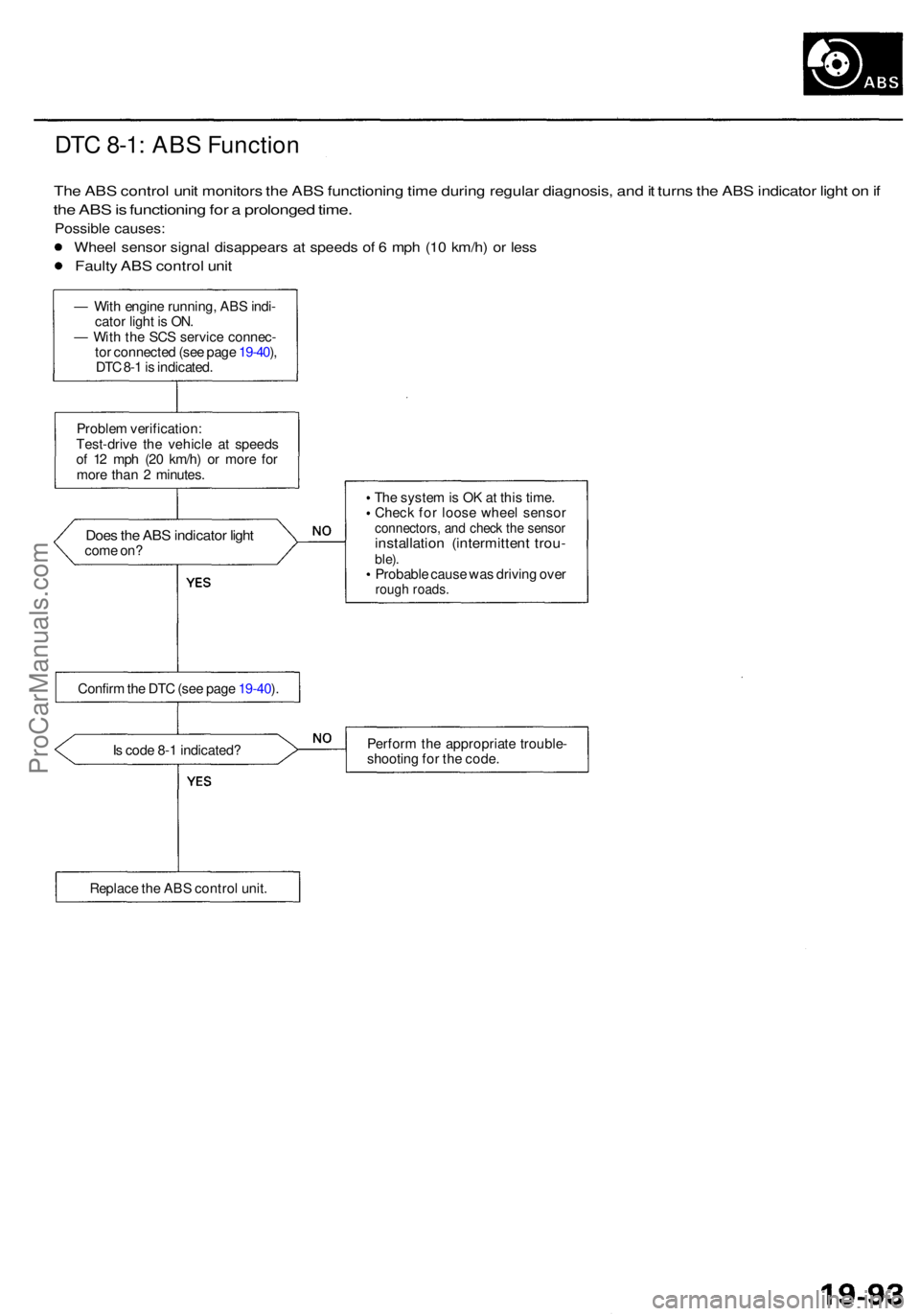
DTC 8-1 : AB S Functio n
The AB S contro l uni t monitor s th e AB S functionin g tim e durin g regula r diagnosis , an d it turn s th e AB S indicato r ligh t o n if
th e AB S is functionin g fo r a prolonge d time .
Possibl e causes :
Wheel senso r signa l disappear s a t speed s o f 6 mp h (1 0 km/h ) o r les s
Fault y AB S contro l uni t
— Wit h engin e running , AB S indi -
cato r ligh t i s ON .
— Wit h th e SC S servic e connec -
to r connecte d (se e pag e 19-40 ),
DT C 8- 1 is indicated .
Proble m verification :
Test-driv e th e vehicl e a t speed s
o f 1 2 mp h (2 0 km/h ) o r mor e fo r
mor e tha n 2 minutes .
Does th e AB S indicato r ligh tcom e on ? Th
e syste m is O K a t thi s time .
Chec k fo r loos e whee l senso r
connectors , an d chec k th e senso rinstallatio n (intermitten t trou -ble).Probabl e caus e wa s drivin g ove rroug h roads .
Is cod e 8- 1 indicated ? Perfor
m th e appropriat e trouble -
shootin g fo r th e code .
Replac e th e AB S contro l unit .
Confir
m th e DT C (se e pag e 19-40 ).
ProCarManuals.com
Page 1142 of 1954
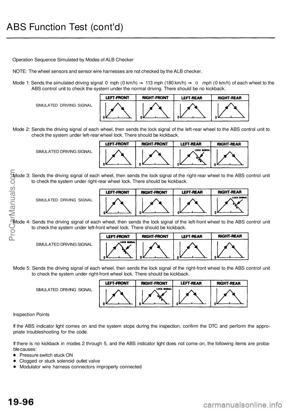
ABS Functio n Tes t (cont'd )
Operatio n Sequenc e Simulate d b y Mode s o f AL B Checke r
NOTE : Th e whee l sensor s an d senso r wir e harnesse s ar e no t checke d b y th e AL B checker .
Mode 1 : Send s th e simulate d drivin g signa l 0 mp h ( 0 km/h ) 11 3 mp h (18 0 km/h ) 0 mph ( 0 km/h ) o f eac h whee l t o th e
AB S contro l uni t t o chec k th e syste m unde r th e norma l driving . Ther e shoul d b e n o kickback .
SIMULATE D DRIVIN G SIGNA L
Mode 2 : Send s th e drivin g signa l o f eac h wheel , the n send s th e loc k signa l o f th e left-rea r whee l t o th e AB S contro l uni t t o
chec k th e syste m unde r left-rea r whee l lock . Ther e shoul d b e kickback .
SIMULATE D DRIVIN G SIGNA L
Mode 3 : Send s th e drivin g signa l o f eac h wheel , the n send s th e loc k signa l o f th e right-rea r whee l t o th e AB S contro l uni t
t o chec k th e syste m unde r right-rea r whee l lock . Ther e shoul d b e kickback .
SIMULATE D DRIVIN G SIGNA L
Inspectio n Point s
I f th e AB S indicato r ligh t come s o n an d th e syste m stop s durin g th e inspection , confir m th e DT C an d perfor m th e appro -
priat e troubleshootin g fo r th e code .
I f ther e is n o kickbac k i n mode s 2 throug h 5 , an d th e AB S indicato r ligh t doe s no t com e on , th e followin g item s ar e proba -
bl e causes :
Pressur e switc h stuc k O N
Clogge d o r stuc k solenoi d outle t valv e
Modulato r wir e harnes s connector s improperl y connecte d
Mod
e 5 : Send s th e drivin g signa l o f eac h wheel , the n send s th e loc k signa l o f th e right-fron t whee l t o th e AB S contro l uni t
t o chec k th e syste m unde r right-fron t whee l lock . Ther e shoul d b e kickback .
SIMULATE D DRIVIN G SIGNA L
Mode 4 : Send s th e drivin g signa l o f eac h wheel , the n send s th e loc k signa l o f th e left-fron t whee l t o th e AB S contro l uni t
t o chec k th e syste m unde r left-fron t whee l lock . Ther e shoul d b e kickback .
SIMULATE D DRIVIN G SIGNA L
ProCarManuals.com
Page 1145 of 1954
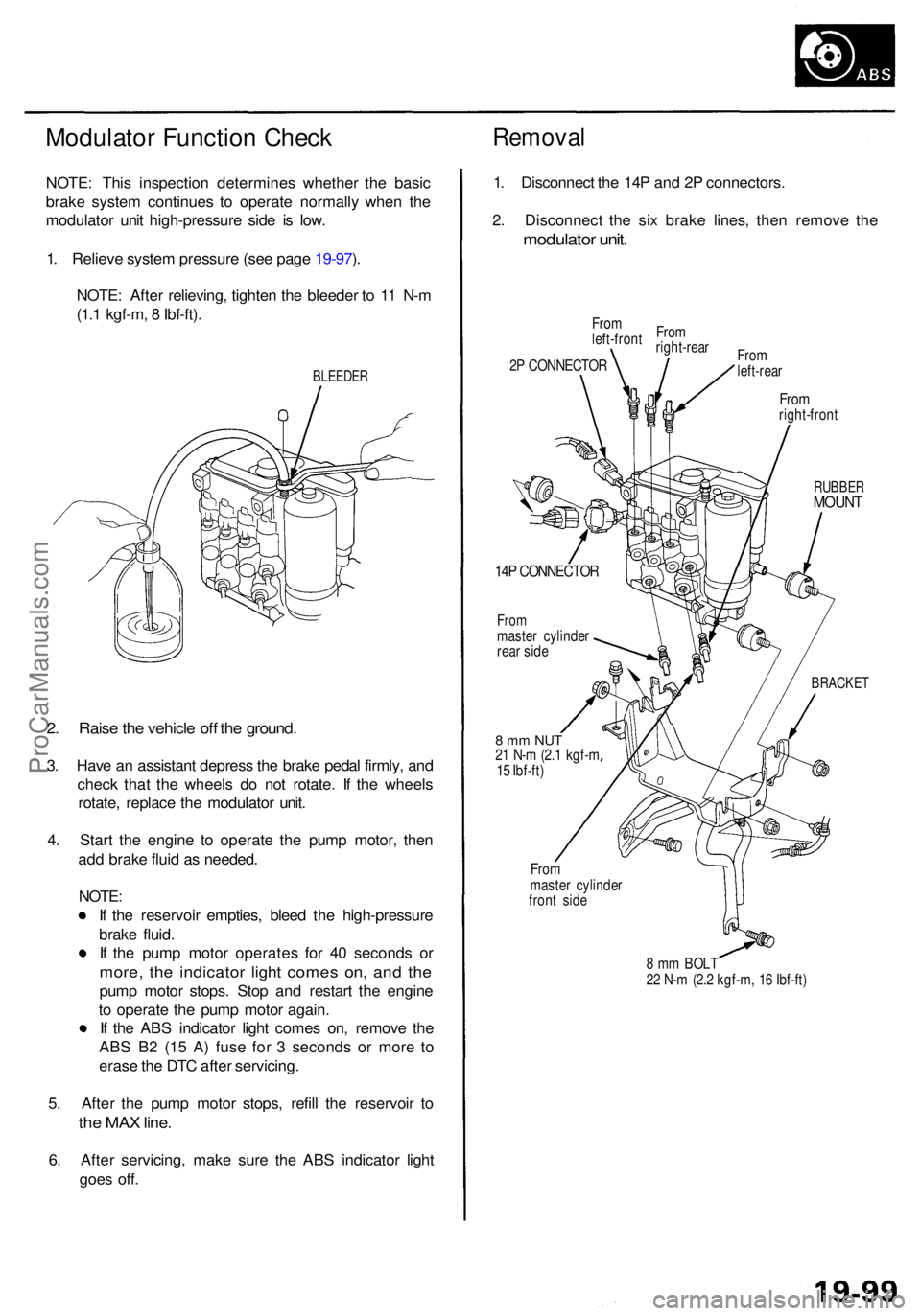
Modulator Functio n Chec kRemova l
NOTE: Thi s inspectio n determine s whethe r th e basi c
brak e syste m continue s t o operat e normall y whe n th e
modulato r uni t high-pressur e sid e i s low .
1 . Reliev e syste m pressur e (se e pag e 19-97 ).
NOTE : Afte r relieving , tighte n th e bleede r t o 1 1 N- m
(1. 1 kgf-m , 8 Ibf-ft) .
BLEEDE R
2. Rais e th e vehicl e of f th e ground .
3. Hav e a n assistan t depres s th e brak e peda l firmly , an d
chec k tha t th e wheel s d o no t rotate . I f th e wheel s
rotate , replac e th e modulato r unit .
4 . Star t th e engin e t o operat e th e pum p motor , the n
ad d brak e flui d a s needed .
NOTE :
I f th e reservoi r empties , blee d th e high-pressur e
brak e fluid .
I f th e pum p moto r operate s fo r 4 0 second s o r
more , th e indicato r ligh t come s on , an d th e
pum p moto r stops . Sto p an d restar t th e engin e
t o operat e th e pum p moto r again .
I f th e AB S indicato r ligh t come s on , remov e th e
AB S B 2 (1 5 A ) fus e fo r 3 second s o r mor e t o
eras e th e DT C afte r servicing .
5 . Afte r th e pum p moto r stops , refil l th e reservoi r t o
th e MA X line .
6. Afte r servicing , mak e sur e th e AB S indicato r ligh t
goe s off . 1
. Disconnec t th e 14 P an d 2 P connectors .
2 . Disconnec t th e si x brak e lines , the n remov e th e
modulato r unit .
From
left-fron tFro
m
right-rea r
2 P CONNECTO R Fro
m
left-rea r
Fromright-fron t
RUBBERMOUNT
14P CONNECTO R
Frommaste r cylinde r
rea r sid e
BRACKE T
8 m m NU T21 N- m (2. 1 kgf- m
1 5 Ibf-ft )
Fro m
maste r cylinde r
fron t sid e
8 m m BOL T
2 2 N- m (2. 2 kgf-m , 1 6 Ibf-ft )
ProCarManuals.com
Page 1149 of 1954
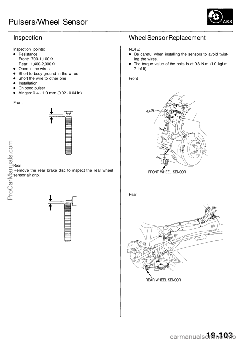
Pulsers/Wheel Senso r
Inspectio n
Inspection points :
Resistanc e
Front: 700-1,10 0
Rear: 1,400-2,00 0
Ope n in th e wire s
Shor t t o bod y groun d i n th e wire s
Shor t th e wir e t o othe r on e
Installatio n
Chippe d pulse r
Air gap : 0.4 - 1. 0 m m (0.0 2 - 0.04 in)
Fron t
Rear
Remov e th e rea r brak e dis c t o inspec t th e rea r whee l
sensor ai r grip .
Whee l Senso r Replacemen t
NOTE:
B e carefu l whe n installin g th e sensor s t o avoi d twist -
in g th e wires .
Th e torqu e valu e o f th e bolt s i s a t 9. 8 N- m (1. 0 kgf-m ,
7 Ibf-ft) .
Front
FRON T WHEE L SENSO R
Rear
REA R WHEE L SENSO R
ProCarManuals.com