1996 ACURA RL KA9 immobilizer
[x] Cancel search: immobilizerPage 541 of 1954

PCM
PCM
COVER
9.8 N-m
(1.0 kgf-m,
7.2 Ibf-ft)
6. After completing your tests, reinstall both PCM's, and destroy the temporary key.
If the inspection for a particular code requires voltage or resistance checks at the PCM connectors, remove the right
door sill molding. Pull the carpet back to expose the PCM. Unbolt the PCM cover, and connect the backprobe sets and
a digital multimeter as described below. Check the system according to the procedure described for the appropriate code(s)
listed on the following pages.
DONOR
KEY
TEMPORARY
KEY
Troubleshooting
Troubleshooting Procedures (cont'd)
IV. Known-Good PCM Substitution
Use the following procedure if you need a known-good PCM to test a vehicle. It allows you to swap an PCM from a
"donor" vehicle without having to program it to the test vehicle's ignition key.
1. Cut a temporary ignition key for the test vehicle with a non-immobilizer key blank.
2. Remove the PCM from the test vehicle.
3. Write the test vehicle's VIN on the PCM you just removed to avoid confusing it with the donor vehicle's PCM.
4. Remove the known-good PCM from the donor vehicle, and install it in the test vehicle.
5. Tape the donor vehicle's ignition key head-to-head to the test vehicle's temporary key. The PCM will recognize the code
from the donor vehicle's key and allow you to start the engine with the temporary key.ProCarManuals.com
Page 1592 of 1954
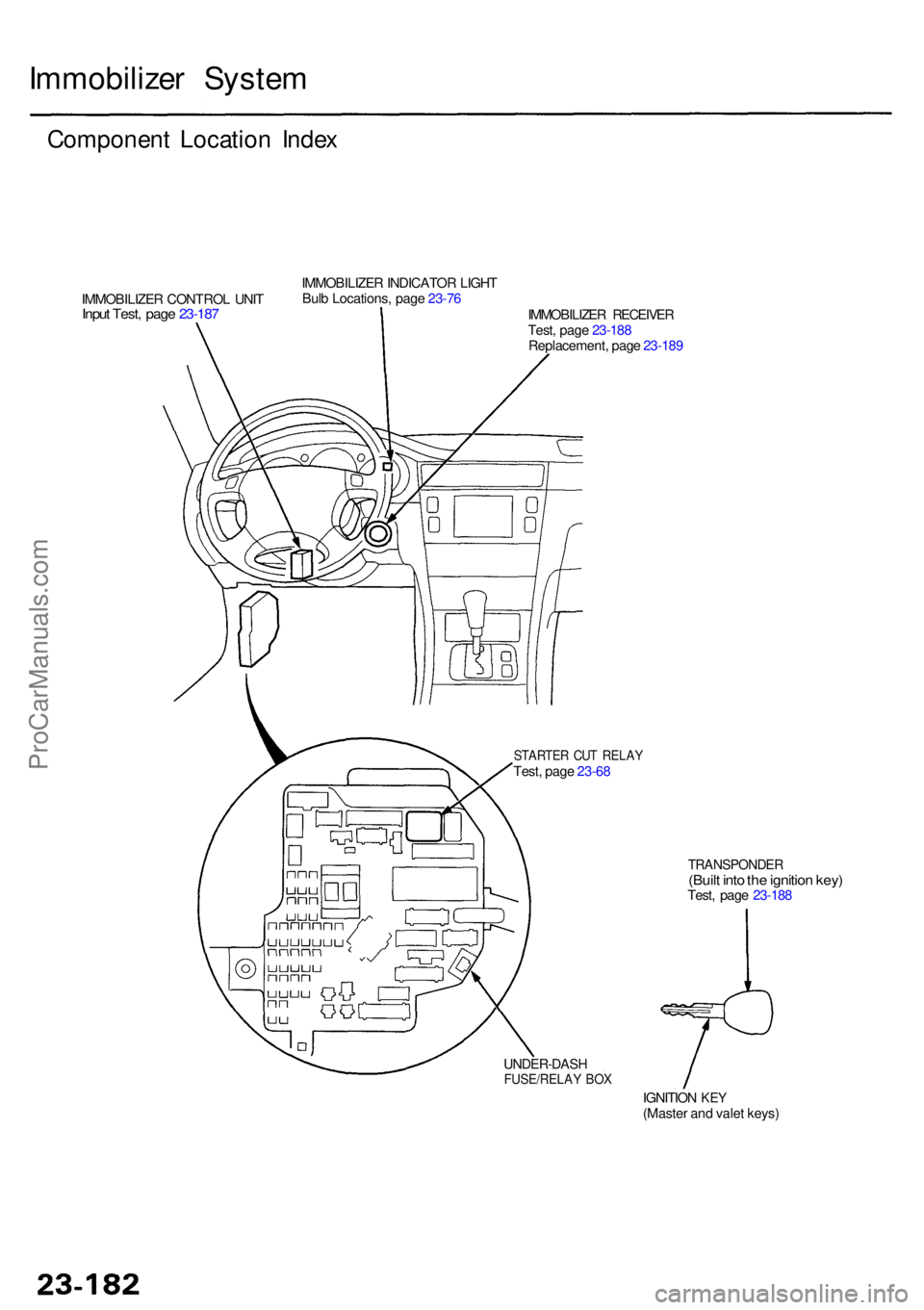
Immobilizer Syste m
Componen t Locatio n Inde x
IMMOBILIZE R CONTRO L UNI TInput Test , pag e 23-18 7
IMMOBILIZE R INDICATO R LIGH T
Bul b Locations , pag e 23-76
IMMOBILIZER RECEIVE R
Test , pag e 23-18 8
Replacement , pag e 23-18 9
STARTE R CU T RELA YTest, pag e 23-6 8
TRANSPONDE R(Built int o th e ignitio n key )Test , pag e 23-18 8
IGNITIO N
KEY(Maste r an d vale t keys )
UNDER-DAS HFUSE/RELAY BO X
ProCarManuals.com
Page 1594 of 1954
Immobilizer Syste m
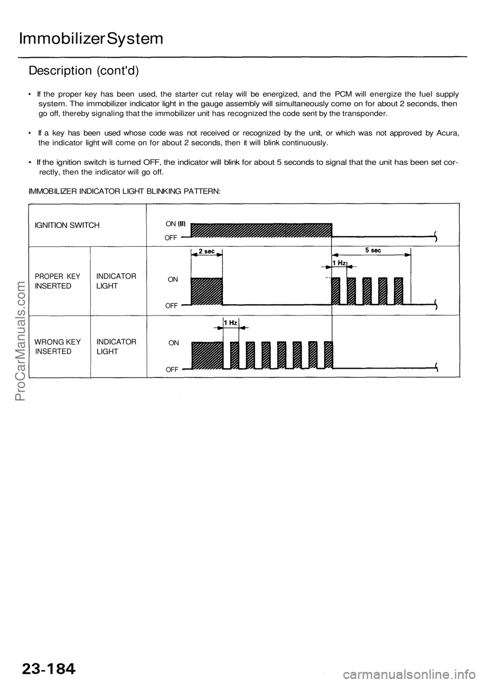
Descriptio n (cont'd )
• I f th e prope r ke y ha s bee n used , th e starte r cu t rela y wil l b e energized , an d th e PC M wil l energiz e th e fue l suppl y
system . Th e immobilize r indicato r ligh t i n th e gaug e assembl y wil l simultaneousl y com e o n fo r abou t 2 seconds , the n
go off , thereb y signalin g tha t th e immobilize r uni t ha s recognize d th e cod e sen t b y th e transponder .
• I f a ke y ha s bee n use d whos e cod e wa s no t receive d o r recognize d b y th e unit , o r whic h wa s no t approve d b y Acura ,
th e indicato r ligh t wil l com e o n fo r abou t 2 seconds , the n it wil l blin k continuously .
• I f th e ignitio n switc h is turne d OFF , th e indicato r wil l blin k fo r abou t 5 second s to signa l tha t th e uni t ha s bee n se t cor -
rectly , the n th e indicato r wil l g o off .
IMMOBILIZE R INDICATO R LIGH T BLINKIN G PATTERN :
WRONG KE Y
INSERTE D
PROPER KE Y
INSERTE D
IGNITION SWITC H
INDICATO R
LIGHT
INDICATO R
LIGHT
ON
OF F
ON
OF F
ON
OF F
ProCarManuals.com
Page 1596 of 1954
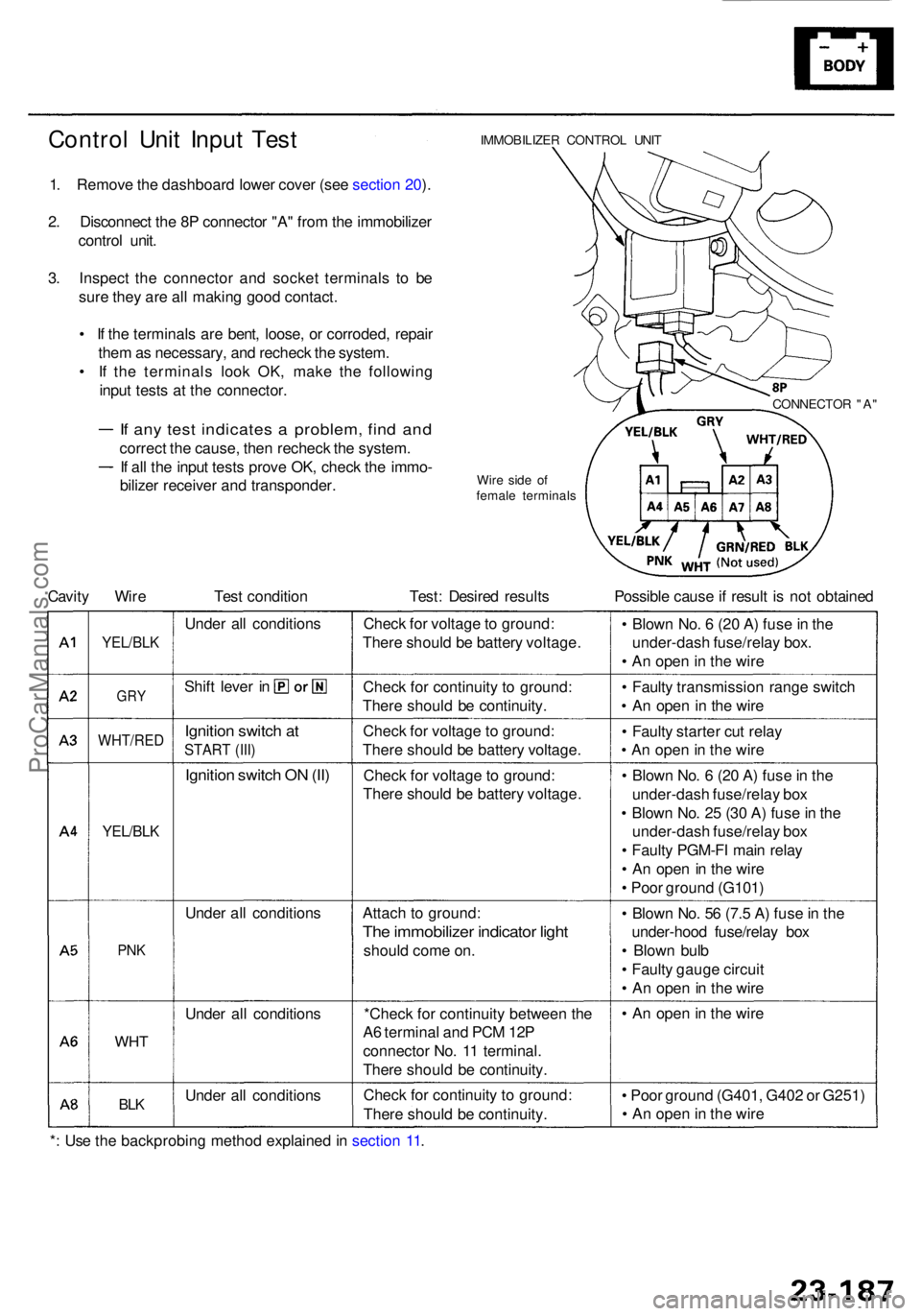
Control Uni t Inpu t Tes t
1. Remov e th e dashboar d lowe r cove r (se e sectio n 20 ).
2 . Disconnec t th e 8 P connecto r "A " fro m th e immobilize r
contro l unit .
3 . Inspec t th e connecto r an d socke t terminal s t o b e
sur e the y ar e al l makin g goo d contact .
• I f th e terminal s ar e bent , loose , o r corroded , repai r
the m as necessary , an d rechec k th e system .
• I f th e terminal s loo k OK , mak e th e followin g
inpu t test s a t th e connector .
If an y tes t indicate s a problem , fin d an d
correc t th e cause , the n rechec k th e system .
If al l th e inpu t test s prov e OK , chec k th e immo -
bilize r receive r an d transponder .
IMMOBILIZER CONTRO L UNI T
Wir e sid e o f
femal e terminal s
Cavity Wir e Tes t conditio n Test : Desire d result s Possibl e caus e if resul t i s no t obtaine d
YEL/BLK
GRY
WHT/RE D
YEL/BLK
PNK
WH T
BLK
Unde r al l condition s
Shif t leve r i n
Ignitio n switc h a t
STAR T (III )
Ignitio n switc h O N (II )
Unde r al l condition s
Unde r al l condition s
Unde r al l condition sChec
k fo r voltag e to ground :
Ther e shoul d b e batter y voltage .
Chec k fo r continuit y t o ground :
Ther e shoul d b e continuity .
Chec k fo r voltag e t o ground :
Ther e shoul d b e batter y voltage .
Chec k fo r voltag e to ground :
Ther e shoul d b e batter y voltage .
Attac h t o ground :
The immobilize r indicato r ligh t
shoul d com e on .
*Chec k fo r continuit y betwee n th e
A 6 termina l an d PC M 12 P
connecto r No . 1 1 terminal .
Ther e shoul d b e continuity .
Chec k fo r continuit y t o ground :
Ther e shoul d b e continuity . •
Poo r groun d (G401 , G40 2 o r G251 )
• A n ope n in th e wir e
•
A n ope n in th e wir e
•
Blow n No . 5 6 (7. 5 A ) fus e in th e
under-hoo d fuse/rela y bo x
• Blow n bul b
• Fault y gaug e circui t
• A n ope n in th e wir e
•
Blow n No . 6 (2 0 A ) fus e in th e
under-das h fuse/rela y bo x
• Blow n No . 2 5 (3 0 A ) fus e in th e
under-das h fuse/rela y bo x
• Fault y PGM-F I mai n rela y
• A n ope n in th e wir e
• Poo r groun d (G101 )
•
Fault y starte r cu t rela y
• A n ope n in th e wir e
•
Fault y transmissio n rang e switc h
• A n ope n i n th e wir e
•
Blow n No . 6 (2 0 A ) fus e in th e
under-das h fuse/rela y box .
• A n ope n in th e wir e
CONNECTO R "A "
*: Us e th e backprobin g metho d explaine d in sectio n 11 .
ProCarManuals.com
Page 1597 of 1954
Immobilizer Syste m
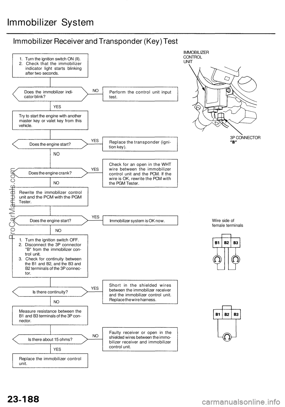
Immobilize r Receive r an d Transponde r (Key ) Tes t
IMMOBILIZE RCONTROLUNIT
Doe s th e immobilize r indi -
cato r blink ? Perfor
m th e contro l uni t inpu t
test .
YES
Try to star t th e engin e wit h anothe r
maste r ke y o r vale t ke y fro m thi s
vehicle .
Doe s th e engin e start ? Replac
e th e transponde r (igni -
tio n key) .
3P CONNECTO R
NO
Doe s th e engin e crank ?
NO
Rewrit e th e immobilize r contro lunit an d th e PC M wit h th e PG MTester .
Check fo r a n ope n i n th e WH T
wir e betwee n th e immobilize r
contro l uni t an d th e PCM . I f th e
wir e is OK , rewrit e th e PC M wit h
th e PG M Tester .
Doe s th e engin e start ?
Immobilizer syste m is O K now . Wir
e sid e o f
femal e terminal s
I s ther e continuity ?
NO
Shor t i n th e shielde d wire s
betwee n th e immobilize r receive r
an d th e immobilize r contro l unit .
Replac e th e wir e harness .
Measur e resistanc e betwee n th e
B 1 an d B 3 terminal s o f th e 3 P con -
nector .
Is ther e abou t 1 5 ohms ?
YES
Fault y receive r o r ope n i n th e
shielde d wire s betwee n th e immo -
bilize r receive r an d immobilize r
contro l unit .
Replac e th e immobilize r contro l
unit .
1
. Tur n th e ignitio n switc h O N (II) .
2 . Chec k tha t th e immobilize r
indicato r ligh t start s blinkin g
afte r tw o seconds .
1 . Tur n th e ignitio n switc h OFF .
2 . Disconnec t th e 3 P connecto r
"B " fro m th e immobilize r con -
trol unit .3. Chec k fo r continuit y betwee nthe B 1 an d B2 , an d th e B 3 an dB2 terminal s o f th e 3 P connec -tor.
NO
YE S
YE S
NO
N
O
YE S
YES
ProCarManuals.com
Page 1598 of 1954
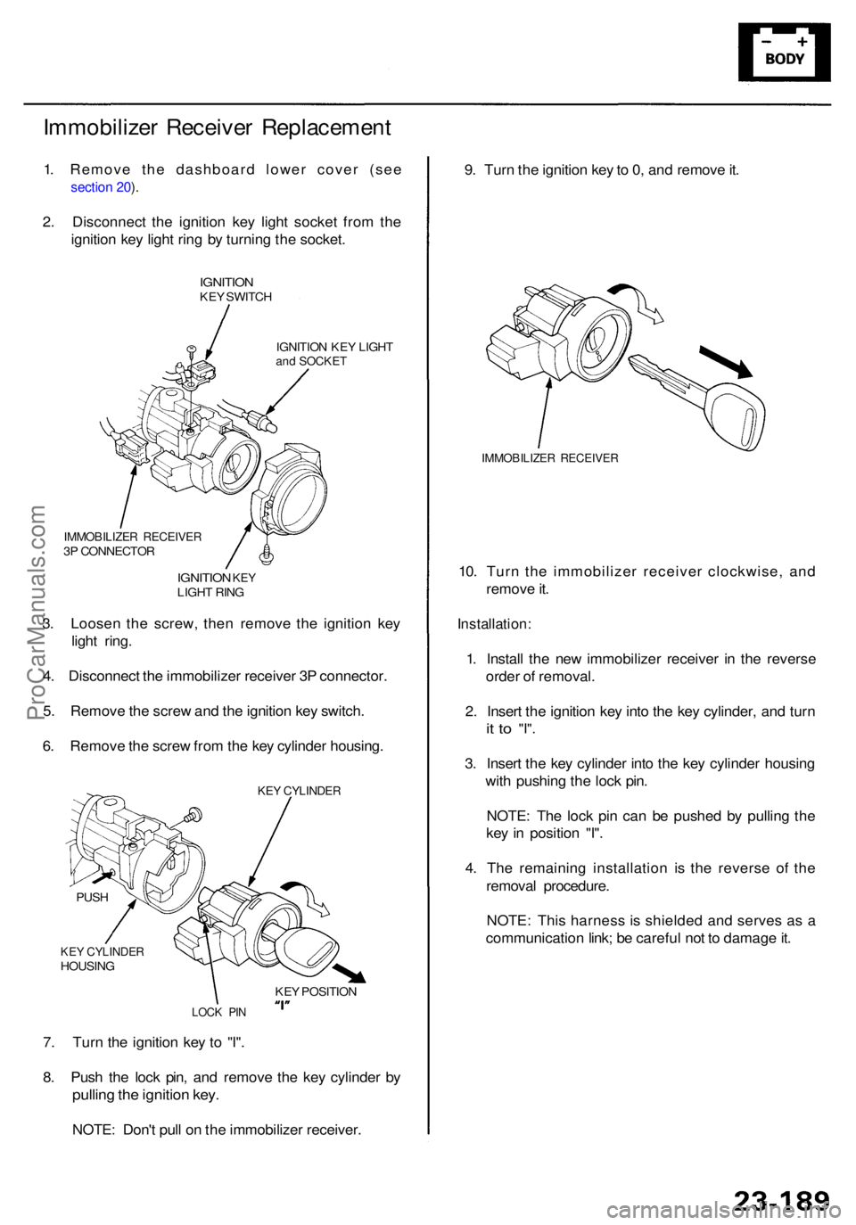
Immobilizer Receive r Replacemen t
1. Remove the dashboard lower cover (see
section 20 ).
2 . Disconnec t th e ignitio n ke y ligh t socke t fro m th e
ignitio n ke y ligh t rin g b y turnin g th e socket .
IGNITIO NKEY SWITC H
IGNITIO N KE Y LIGH T
and SOCKE T
9. Tur n th e ignitio n ke y to 0, an d remov e it .
IMMOBILIZE R RECEIVE R
10. Tur n th e immobilize r receive r clockwise , an d
remov e it .
Installation :
1. Instal l th e ne w immobilize r receive r i n th e revers e
orde r o f removal .
2 . Inser t th e ignitio n ke y int o th e ke y cylinder , an d tur n
it t o "I" .
3. Inser t th e ke y cylinde r int o th e ke y cylinde r housin g
wit h pushin g th e loc k pin .
NOTE : Th e loc k pi n ca n b e pushe d b y pullin g th e
ke y i n positio n "I" .
4 . Th e remainin g installatio n i s th e revers e o f th e
remova l procedure .
NOTE : Thi s harnes s i s shielde d an d serve s a s a
communicatio n link ; b e carefu l no t t o damag e it .
7 . Tur n th e ignitio n ke y t o "I" .
8 . Pus h th e loc k pin , an d remov e th e ke y cylinde r b y
pullin g th e ignitio n key .
NOTE : Don' t pul l o n th e immobilize r receiver .
3
. Loose n th e screw , the n remov e th e ignitio n ke y
ligh t ring .
4 . Disconnec t th e immobilize r receive r 3 P connector .
5 . Remov e th e scre w an d th e ignitio n ke y switch .
6 . Remov e th e scre w fro m th e ke y cylinde r housing .
IMMOBILIZE R RECEIVE R3P CONNECTO R
IGNITION KEYLIGH T RIN G
KEY CYLINDE RHOUSING
PUS
H
LOC K PI N
KEY POSITIO N
KEY CYLINDE R
ProCarManuals.com