1996 ACURA RL KA9 cooling
[x] Cancel search: coolingPage 1 of 1954

General Info
Specifications
Maintenance
*Engine Electrical
Engine
Cooling
Fuel and Emissions
*TransaxleSteering
Suspension
*Brakes (Including ABS,
TCS and VSA)
*Body
*Heating, Ventilation and Air Conditioning
*Body Electrical
*Restraints
1996±0 4 3.5RL Main Menu
As sections w/ * include SRS components,
special precautions are required when servicing.
ProCarManuals.com
Page 139 of 1954

Engine Coolant Temperature (ECT) Sensor
The HDS or the scan tool indicates Diagnostic Trouble Code (DTC) P0116: A range/performance problem in the
Engine Coolant Temperature (ECT) sensor.
The ECT Sensor is a temperature dependent resistor (thermistor). The resistance of the thermistor decreases as the engine
coolant temperature increases as shown below.
NOTE: If DTC P0117 and/or P0118 are stored at the same time as DTC P0116 and/or P0125, troubleshoot those DTCs first,
then troubleshoot DTC P0116 and/or P0125.
Possible Cause
• ECT sensor deterioration
• Malfunction in the thermostat and the cooling system
Troubleshooting Flowchart
— The MIL has been reported on.
— DTC P0116 is stored.
Problem verification:
1. Turn the ignition switch OFF.
2. Check the ETC output tempera-
ture or voltage with the HDS or
the scan tool.
Is about 176°F (80°C) or high-
er, or 0.86 V or less indicated?
YES
Problem verification:
1. Note current coolant
temperature.
2. Turn the ignition switch OFF.
3. Cool the engine for 1 hour.
4. Check the ETC output temper-
ature or voltage with the HDS
or the scan tool.
Does the ECT change 3.6°F
(2°C) or more?
NO
Replace the ECT sensor.
NO
YES
Problem verification:
1. Note current coolant
temperature.
2. Start the engine. Hold the
engine speed at 3,000 rpm
with no load (in Park or neu-
tral)
until
the
radiator
fan
comes on, then let it idle.
3. Check the ETC output temper-
ature or voltage with the HDS
or the scan tool.
Does the ECT change 3.6°F
(2°C) or more?
NO
YES
Intermittent failure, system is OK
at this time. Check the thermo-
stat and the cooling system.
Intermittent failure, system is OK
at this time. Check the thermo-
stat and the cooling system.
(cont'd)ProCarManuals.com
Page 140 of 1954

PGM-FI System
Engine Coolant Temperature (ECT) Sensor (cont'd)
The HDS or the scan tool indicates Diagnostic Trouble Code (DTC) P0125: Engine Coolant Temperature
(ECT) sensor malfunction/slow response.
Is about 86°F (30°C) or less, or
2.61 V or higher indicated?
Intermittent failure, system is OK
at this time.
Check the thermostat and the
cooling system.
YES
Problem verification:
1. Let it idle for 6 minutes.
2. Check the ETC output temper-
ature or voltage with the HDS
or the scan tool.
Is about 86°F (30°C) or less, or
2.61 V or higher indicated?
Intermittent failure, system is OK
at this time.
Check the thermostat and the
cooling system.
YES
Replace the ECT sensor.
11-50
Problem verification:
1. Start the engine, and let it idle.
2. Check the ETC output temper-
ature or voltage with the HDS
or the scan tool.
— The MIL has been reported on
— DTC P0125 is stored.ProCarManuals.com
Page 157 of 1954

Thermostat
The HDS or the scan tool indicates Diagnostic Trouble Code (DTC) P1486: Range/Performance Problem in
Thermostat.
NOTE: If the DTCs listed below are stored at the same time as DTC P1486, troubleshoot those DTCs first, then recheck for
P1486.
P0107, P0108, P1128, P1129: MAP Sensor
P2227, P2228, P2229: Barometric Pressure Circuit
P1259, P1279: VTEC system
P0401: EGR Flow Insufficient
P0404: EGR Valve Lift Insufficient
P0406: EGR Valve Position Sensor High Voltage
P0125, P0116, P0117, P0118: Engine Coolant Temperature Circuit
P0112, P0113: Intake Air Temperature Circuit
P0345, P0349, P1336, P1337: CKP Sensor 1/2
P0300: Random Misfire
P0301, P0302, P0303, P0304, P0305, P0306: Cylinder 1, 2, 3, 4, 5 or 6 Misfire detected.
P0506, P0507: Idle Control System Malfunction
P0511: Idle Air Control Valve
DTC P1486 can set occasionally when the hood is opened.
Troubleshooting
— The MIL has been reported on.
— DTC P1486 is stored.
1. Turn the ignition Switch OFF.
2. Check the engine coolant
level.
Is the engine coolant level low?
Does the radiator fan keep
running?
YES
Check the radiator fan circuit,
radiator fan switch circuit and
the radiator fan switch.
It they are OK, substitute the
PCM and recheck.
If the symptom/indication goes
away, replace the original PCM.
Refill the engine coolant. If neces-
sary, check the cooling system.
Test the thermostat.
Check for the radiator for circuit:
1. Turn the ignition switch ON
(II).
2. Check the radiator fan.ProCarManuals.com
Page 814 of 1954

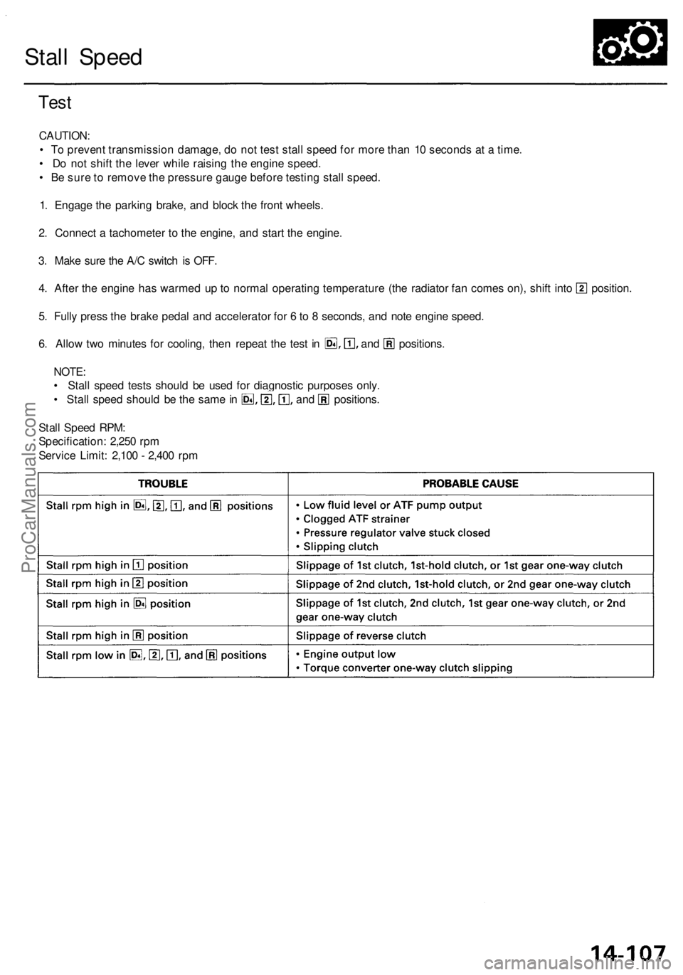
Stall Speed
Test
CAUTION:
• To prevent transmission damage, do not test stall speed for more than 10 seconds at a time.
• Do not shift the lever while raising the engine speed.
• Be sure to remove the pressure gauge before testing stall speed.
1. Engage the parking brake, and block the front wheels.
2. Connect a tachometer to the engine, and start the engine.
3. Make sure the A/C switch is OFF.
4. After the engine has warmed up to normal operating temperature (the radiator fan comes on), shift into position.
5. Fully press the brake pedal and accelerator for 6 to 8 seconds, and note engine speed.
6. Allow two minutes for cooling, then repeat the test in and positions.
NOTE:
• Stall speed tests should be used for diagnostic purposes only.
• Stall speed should be the same in and positions.
Stall Speed RPM:
Specification: 2,250 rpm
Service Limit: 2,100 - 2,400 rpmProCarManuals.com
Page 1428 of 1954

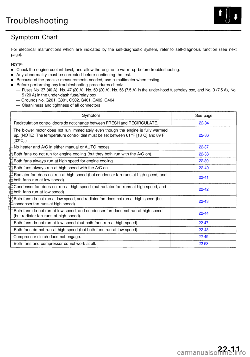
Troubleshooting
Symptom Char t
For electrica l malfunction s whic h ar e indicate d b y th e self-diagnosti c system , refe r t o self-diagnosi s functio n (se e nex t
page) .
NOTE :
Check th e engin e coolan t level , an d allo w th e engin e t o war m u p befor e troubleshooting .
An y abnormalit y mus t b e correcte d befor e continuin g th e test .
Becaus e o f th e precis e measurement s needed , us e a multimete r whe n testing .
Befor e performin g an y troubleshootin g procedure s check :
— Fuse s No . 3 7 (4 0 A) , No . 4 7 (2 0 A) , No . 5 0 (2 0 A) , No . 5 6 (7. 5 A ) i n th e under-hoo d fuse/rela y box , an d No . 3 (7. 5 A) , No .
5 (2 0 A ) i n th e under-das h fuse/rela y bo x
— Ground s No . G201 , G301 , G302 , G401 , G402 , G40 4
— Cleanlines s an d tightnes s o f al l connector s
Symptom
Recirculatio n contro l door s d o no t chang e betwee n FRES H an d RECIRCULATE .
Th e blowe r moto r doe s no t ru n immediatel y eve n thoug h th e engin e i s full y warme d
up . (NOTE : Th e temperatur e contro l dia l mus t b e se t betwee n 6 1 °F [18°C ] an d 89° F
[32°C]. )
No heate r an d A/ C in eithe r manua l o r AUT O modes .
Bot h fan s d o no t ru n fo r engin e coolin g (bu t the y bot h ru n wit h th e A/ C on) .
Both fan s alway s ru n a t hig h spee d fo r engin e cooling .
Both fan s alway s ru n a t hig h spee d wit h th e A/ C on .
Radiato r fa n doe s no t ru n a t hig h spee d (bu t condense r fa n run s a t hig h speed , an d
bot h fan s ru n a t lo w speed) .
Condense r fa n doe s no t ru n a t hig h spee d (bu t radiato r fa n run s a t hig h speed , an d
bot h fan s ru n a t lo w speed) .
Bot h fan s d o no t ru n a t lo w speed , an d radiato r fa n doe s no t ru n a t hig h spee d (bu t
condense r fa n run s a t hig h speed) .
Bot h fan s d o no t ru n a t low speed , an d condense r fa n doe s no t ru n a t hig h spee d
(bu t radiato r fa n run s a t hig h speed) .
Bot h fan s d o no t ru n a t lo w spee d (bu t bot h fan s ru n a t hig h speed) .
Bot h fan s d o no t ru n a t hig h spee d (bu t bot h fan s ru n a t lo w speed) .
Compresso r clutc h doe s no t engage .
Bot h fan s an d compresso r d o no t wor k a t all . Se
e pag e
22-3 4
22-3 6
22-3 7
22-3 8
22-39
22-4 0
22-41
22-42
22-4 3
22-4 4
22-47
22-48
22-4 9
22-53
ProCarManuals.com
Page 1454 of 1954

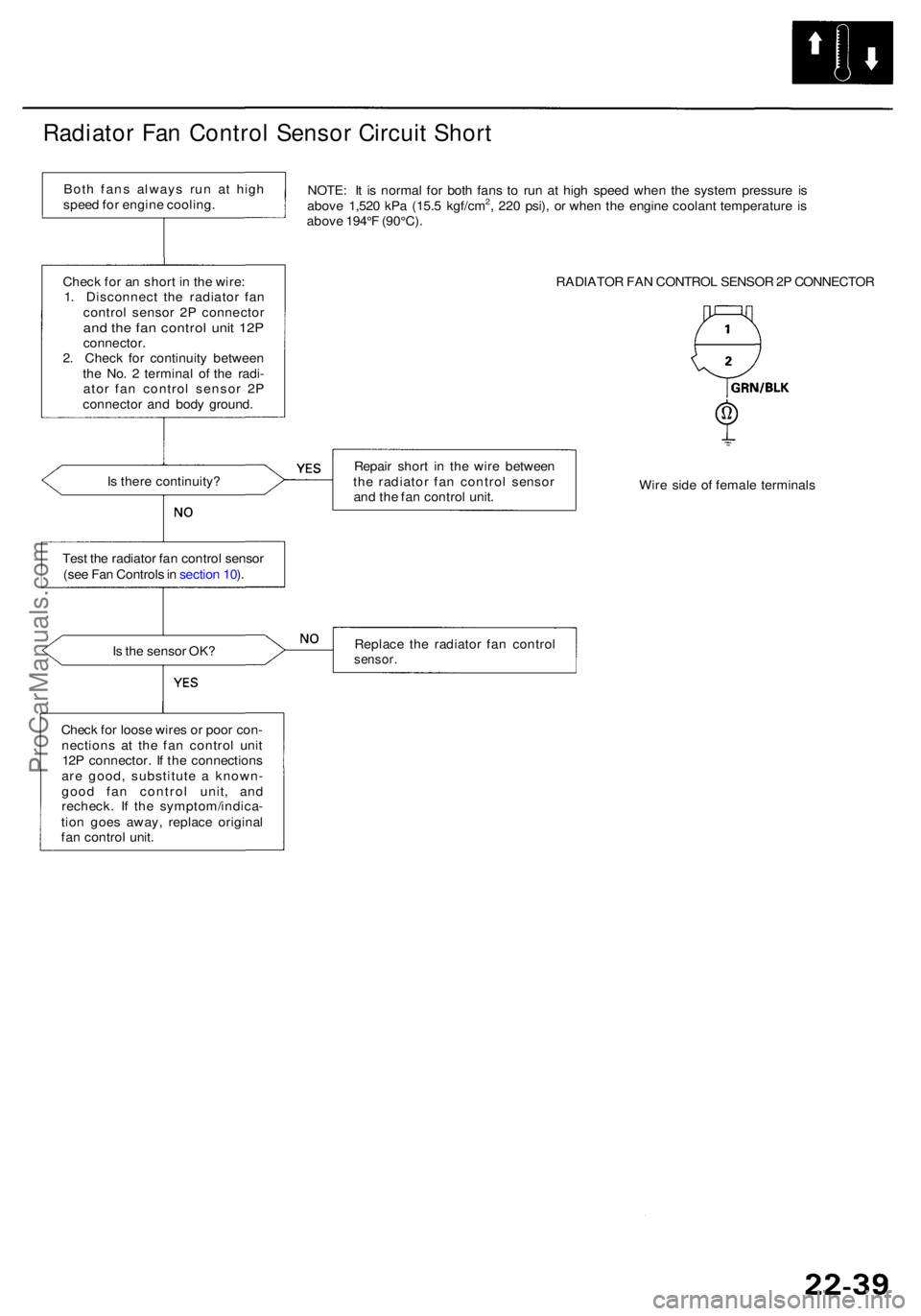
Radiator Fa n Contro l Senso r Circui t Shor t
NOTE : I t i s norma l fo r bot h fan s t o ru n a t hig h spee d whe n th e syste m pressur e i s
abov e 1,52 0 kP a (15. 5 kgf/cm2, 22 0 psi) , o r whe n th e engin e coolan t temperatur e i s
abov e 194° F (90°C) .
RADIATOR FA N CONTRO L SENSO R 2P CONNECTO R
I s ther e continuity ? Repai
r shor t i n th e wir e betwee n
th e radiato r fa n contro l senso r
an d th e fa n contro l unit . Wir
e sid e o f femal e terminal s
Tes t th e radiato r fa n contro l senso r
(se e Fa n Control s in sectio n 10 ).
I s th e senso r OK ? Replac
e th e radiato r fa n contro l
sensor.
Check fo r loos e wire s o r poo r con -
nection s a t th e fa n contro l uni t
12 P connector . I f th e connection s
ar e good , substitut e a known -
goo d fa n contro l unit , an d
recheck . I f th e symptom/indica -
tio n goe s away , replac e origina l
fa n contro l unit .
Chec
k fo r a n shor t i n th e wire :
1 . Disconnec t th e radiato r fa n
contro l senso r 2 P connecto r
and th e fa n contro l uni t 12 Pconnector .
2 . Chec k fo r continuit y betwee n
th e No . 2 termina l o f th e radi -
ato r fa n contro l senso r 2 P
connecto r an d bod y ground .
Bot
h fan s alway s ru n a t hig h
spee d fo r engin e cooling .
ProCarManuals.com