1996 ACURA RL KA9 steering wheel adjustment
[x] Cancel search: steering wheel adjustmentPage 275 of 1954

Navigation System
System Diagnosis Mode (cont'd)
GPS Offset Time
This screen is for factory use only. It allows adjustment
of the GPS time. This display updates in real time.
• "GPS Time" is the time as received from the GPS
satellites. It is in Greenwich Mean Time (GMT).
• "System Time" is the internal time used by the navi-
gation unit to calculate your position on the map.
It is also in Greenwich Mean Time (GMT).
• "Display Time" is the time shown on Setup screen 2
"Adjust Time Zone/Clock", and reflects any changes
due to daylight savings time or time adjustments
entered by the customer.
• Date, Hour, Minute, and "Set" buttons should not be
used.
Mic Level
This diagnostic allows you to independently test the
microphone and the TALK and BACK buttons on the
steering wheel (voice control switch). The microphone
and voice control switch are used to activate the voice
control system. The microphone is located near the map
light in the ceiling. It is directional, and works best if the
voice is coming from the drivers seat.
• Press the TALK button on the steering wheel, and in a
normal voice say "testing". The TALK indicator on
the screen should momentarily become green, and
the text "Now Recording..." should appear in yellow.
In addition, the Mic Level indicator should move at
least to the 6th bar. If the Talk indicator on the screen
does not briefly become green, then check the wiring
from the steering wheel talk button to the navigation
unit. If there is no "Mic Level" movement when you
speak, then you should check the wire running from
the microphone to the control unit.
• Press the BACK button on the steering wheel. This
should cause the Cancel indicator on the screen to
momentarily become green. If it does not briefly
change to green, then check the wiring from the
steering wheel BACK button to the navigation unit.ProCarManuals.com
Page 968 of 1954
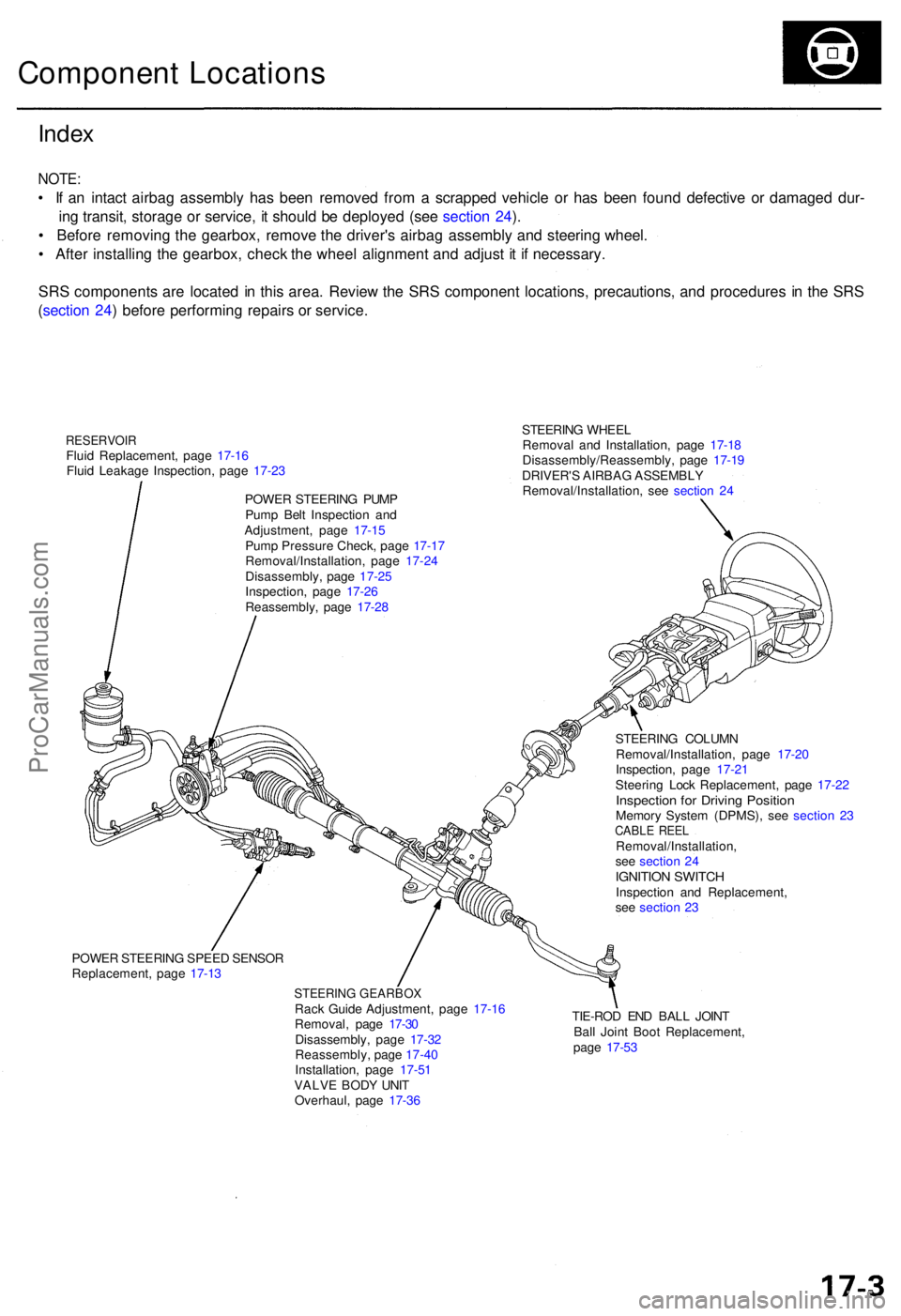
STEERING WHEE L
Remova l an d Installation , pag e 17-1 8
Disassembly/Reassembly , pag e 17-1 9
DRIVER' S AIRBA G ASSEMBL Y
Removal/Installation , se e sectio n 2 4
Inde x
NOTE :
• I f a n intac t airba g assembl y ha s bee n remove d fro m a scrappe d vehicl e o r ha s bee n foun d defectiv e o r damage d dur -
in g transit , storag e o r service , i t shoul d b e deploye d (se e sectio n 24 ).
• Befor e removin g th e gearbox , remov e th e driver' s airba g assembl y an d steerin g wheel .
• Afte r installin g th e gearbox , chec k th e whee l alignmen t an d adjus t i t i f necessary .
SR S component s ar e locate d in thi s area . Revie w th e SR S componen t locations , precautions , an d procedure s i n th e SR S
( sectio n 24 ) befor e performin g repair s o r service .
Componen t Location s
RESERVOI RFluid Replacement , pag e 17-1 6
Flui d Leakag e Inspection , pag e 17-2 3
POWE R STEERIN G PUM P
Pum p Bel t Inspectio n an d
Adjustment , pag e 17-1 5
Pum p Pressur e Check , pag e 17-1 7
Removal/Installation , pag e 17-2 4
Disassembly , pag e 17-2 5
Inspection , pag e 17-2 6
Reassembly , pag e 17-2 8
POWE R STEERIN G SPEE D SENSO R
Replacement , pag e 17-1 3
STEERIN G GEARBO XRack Guid e Adjustment , pag e 17-1 6
Removal , pag e 17-3 0
Disassembly , pag e 17-3 2
Reassembly , pag e 17-4 0
Installation , pag e 17-5 1
VALV E BOD Y UNI T
Overhaul , pag e 17-3 6 TIE-RO
D EN D BAL L JOIN T
Bal l Join t Boo t Replacement ,
pag e 17-5 3
STEERIN
G COLUM N
Removal/Installation , pag e 17-2 0
Inspection , pag e 17-2 1
Steerin g Loc k Replacement , pag e 17-2 2
Inspectio n fo r Drivin g Positio nMemory Syste m (DPMS), see sectio n 2 3CABL E REE LRemoval/Installation ,
se e sectio n 2 4
IGNITIO N SWITC HInspectio n an d Replacement ,
se e sectio n 2 3
ProCarManuals.com
Page 977 of 1954

Inspection an d Adjustmen t
Steering Operatio n
Place th e fron t wheel s i n th e straigh t ahea d position ,
an d measur e th e distanc e th e steerin g whee l ca n b e
turne d withou t movin g th e fron t wheels .
ROTATIONA L PLAY : 0 - 1 0 m m (0 - 0.3 9 in )
If th e pla y exceed s th e servic e limit, perfor m rack guid e
adjustmen t (se e pag e 17-16 ).
I f th e pla y i s stil l excessiv e afte r rac k guid e adjustment ,
inspec t th e steerin g linkag e an d gearbo x (se e pag e
17-14 ).
Powe r Assis t Chec k wit h Vehicl e
Parked
1. Chec k th e powe r steerin g flui d leve l (se e pag e 17-16 )
an d pum p bel t tensio n (se e pag e 17-15 ).
2 . Star t th e engine , allo w it t o idle , an d tur n th e steer -
in g whee l fro m lock-to-loc k severa l time s t o war m
up th e fluid .
3. Attac h a sprin g scal e to th e steerin g wheel . Wit h th e
engin e idlin g an d th e vehicl e o n a clean , dr y floor ,
pul l th e scal e a s shown . Rotat e th e steerin g whee l
mor e tha n 9 0 degre e angl e b y pullin g th e sprin g
scale . Rea d th e figur e o n th e sprin g scal e whil e th e
steerin g whee l i s in motion .
4 . Th e scal e shoul d rea d n o mor e the n 2 5 N (2. 6 kgf ,
5. 7 Ibf) . I f i t read s more , g o o n to ste p 5 .
5 . Sto p th e engine . Disconnec t th e senso r inle t hos e
fro m th e powe r steerin g spee d sensor , an d plu g th e
hos e an d th e senso r fittin g a s shown .
6 . Star t th e engine , an d le t i t idle .
• I f th e readin g i s stil l mor e tha n 2 5 N (2. 6 kgf , 5. 7
Ibf ) th e powe r steerin g spee d senso r i s OK .
Proble m is i n th e pum p o r valv e bod y uni t (se e
Genera l Troubleshooting) .
• I f th e readin g is no w 2 5 N (2. 6 kgf , 5. 7 Ibf ) o r less ,
powe r steerin g spee d senso r leak s internally .
Replac e th e senso r (se e pag e 17-13 ).
ProCarManuals.com
Page 1026 of 1954
Wheel Alignment
Caster
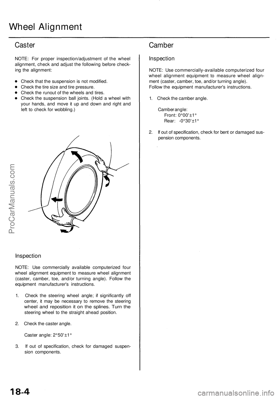
NOTE: For proper inspection/adjustment of the wheel
alignment, check and adjust the following before check-
ing the alignment:
Check that the suspension is not modified.
Check the tire size and tire pressure.
Check the runout of the wheels and tires.
Check the suspension ball joints. (Hold a wheel with
your hands, and move it up and down and right and
left to check for wobbling.)
Inspection
NOTE: Use commercially available computerized four
wheel alignment equipment to measure wheel alignment
(caster, camber, toe, and/or turning angle). Follow the
equipment manufacturer's instructions.
1. Check the steering wheel angle; if significantly off
center, it may be necessary to remove the steering
wheel and reposition it on the splines. Turn the
steering wheel to the straight ahead position.
2. Check the caster angle.
Caster angle: 2°50'±1°
3. If out of specification, check for damaged suspen-
sion components.
Camber
Inspection
NOTE: Use commercially-available computerized four
wheel alignment equipment to measure wheel align-
ment (caster, camber, toe, and/or turning angle).
Follow the equipment manufacturer's instructions.
1. Check the camber angle.
Camber angle:
Front: 0°00'±1°
Rear: -0°30'±1°
2. If out of specification, check for bent or damaged sus-
pension components.ProCarManuals.com
Page 1027 of 1954
Front Toe Inspection/Adjustment
NOTE: Use commercially-available computerized four
wheel alignment equipment to measure wheel align-
ment (caster, camber, toe, and/or turning angle).
Follow the equipment manufacturer's instructions.
1. Check the tire pressure.
2. Center the steering wheel spokes.
3. Check the toe with the wheels pointed straight
ahead.
Front toe: 0 ± 2 mm (0±1/16 in)
— If adjustment is required, go on to step 4.
— If no adjustment is required, remove the align-
ment equipment.
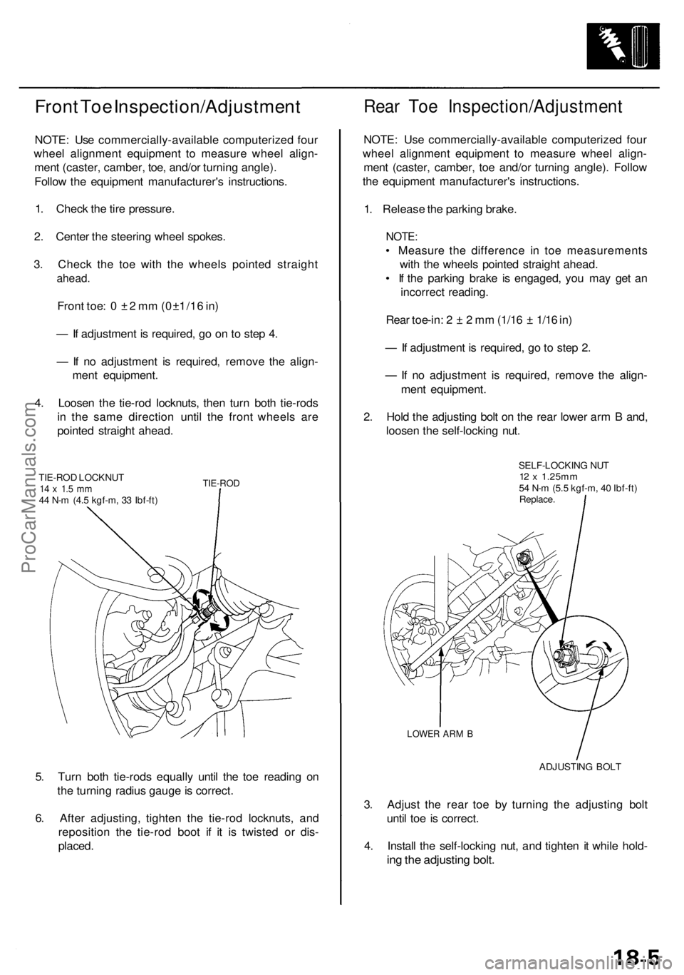
4. Loosen the tie-rod locknuts, then turn both tie-rods
in the same direction until the front wheels are
pointed straight ahead.
TIE-ROD LOCKNUT
14 x 1.5 mm
44 N-m (4.5 kgf-m, 33 Ibf-ft)
TIE-ROD
5. Turn both tie-rods equally until the toe reading on
the turning radius gauge is correct.
6. After adjusting, tighten the tie-rod locknuts, and
reposition the tie-rod boot if it is twisted or dis-
placed.
Rear Toe Inspection/Adjustment
NOTE: Use commercially-available computerized four
wheel alignment equipment to measure wheel align-
ment (caster, camber, toe and/or turning angle). Follow
the equipment manufacturer's instructions.
1. Release the parking brake.
NOTE:
• Measure the difference in toe measurements
with the wheels pointed straight ahead.
• If the parking brake is engaged, you may get an
incorrect reading.
Rear toe-in: 2 ± 2 mm (1/16 ± 1/16 in)
— If adjustment is required, go to step 2.
— If no adjustment is required, remove the align-
ment equipment.
2. Hold the adjusting bolt on the rear lower arm B and,
loosen the self-locking nut.
SELF-LOCKING NUT
12 x 1.25mm
54 N-m (5.5 kgf-m, 40 Ibf-ft)
Replace.
LOWER ARM B
ADJUSTING BOLT
3. Adjust the rear toe by turning the adjusting bolt
until toe is correct.
4. Install the self-locking nut, and tighten it while hold-
ing the adjusting bolt.ProCarManuals.com
Page 1949 of 1954
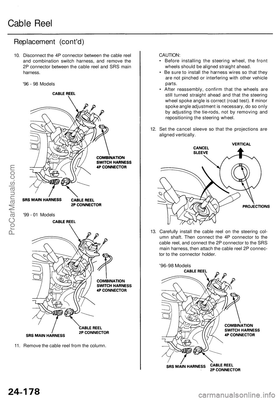
11. Remove the cable reel from the column.
13. Carefully install the cable reel on the steering col-
umn shaft. Then connect the 4P connector to the
cable reel, and connect the 2P connector to the SRS
main harness, then attach the cable reel 2P connec-
tor to the connector holder.
'96-98 Models
'99 - 01 Models
CAUTION:
• Before installing the steering wheel, the front
wheels should be aligned straight ahead.
• Be sure to install the harness wires so that they
are not pinched or interfering with other vehicle
parts.
• After reassembly, confirm that the wheels are
still turned straight ahead and that the steering
wheel spoke angle is correct (road test). If minor
spoke angle adjustment is necessary, do so only
by adjusting the tie-rods, not by removing and
repositioning the steering wheel.
12. Set the cancel sleeve so that the projections are
aligned vertically.
Replacement (cont'd)
10. Disconnect the 4P connector between the cable reel
and combination switch harness, and remove the
2P connector between the cable reel and SRS main
harness.
'96 - 98 Models
Cable ReelProCarManuals.com