1996 ACURA RL KA9 clutch
[x] Cancel search: clutchPage 195 of 1954

From pag e 14-4
Chec k Torqu e Converte r Clutc h
Solenoi d Valv e A fo r a Shor t
Circuit :
1 . Disconnec t th e 2 P connecto r
from th e torqu e converte rclutch solenoi d valve s A an d B .2. Chec k fo r continuit y betwee n
th e E1 3 an d A2 6 terminals .
Is ther e continuity ?
NO
Repai r shor t t o groun d in th e wir ebetwee n th e E1 3 termina l an d th etorqu e converte r clutc h solenoi dvalve A .
Measur e Torqu e Converte r Clutc h
Solenoi d Valv e A Resistanc e a t
th e Solenoi d Connector :
Measur e th e resistanc e betwee n
the No . 2 termina l o f th e torqu econverte r clutc h solenoi d connec -tor an d bod y ground .
Is th e resistanc e 12-25
NO
Chec k fo r ope n i n th e wir e
betwee n th e E1 3 termina l an d th e
torqu e converte r clutc h solenoi d
valv e A .
I s ther e voltage ?
YES
Chec k fo r ope n i n th e wir e
betwee n th e E 1 termina l an d th e
under-hoo d fuse/rela y box .
Replac e th e torqu e converte r
clutc h solenoi d valve s A an d B .
Chec
k th e V B SO L Voltage :
1. Tur n th e ignitio n switc h O N (II) .2. Measur e th e voltag e betwee n
th e E 1 an d A2 6 terminals .
ProCarManuals.com
Page 197 of 1954

From pag e 14-6
Chec k Torqu e Converte r Clutc h
Solenoi d Valv e B fo r a Shor t
Circuit :
1 . Disconnec t th e 2 P connecto r
fro m th e torqu e converte r
clutch solenoi d valve s A an d B .2. Chec k fo r continuit y betwee n
th e E2 6 an d A2 6 terminals .
I s ther e continuity ?
NO
Repai r shor t t o groun d in th e wir e
betwee n th e E2 6 termina l an d th e
torqu e converte r clutc h solenoi d
valv e B .
Measur e Torqu e Converte r Clutc h
Solenoi d Valv e B Resistanc e a t th e
Solenoi d Connector :
Measure th e resistanc e betweenthe No . 1 termina l o f th e torqu e
converte r clutc h solenoi d connec -
tor an d bod y ground .
Is th e resistanc e 12-25
NO
Chec k fo r ope n i n th e wir e
betwee n th e E2 6 termina l an d th e
torqu e converte r clutc h solenoi d
valve B .
Is ther e voltage ? Chec
k fo r ope n i n th e wir e
betwee n th e E 1 termina l an d th e
under-hoo d fuse/rela y box .
Chec
k th e V B SO L Voltage :
1. Tur n th e ignitio n switc h O N (II) .2. Measur e th e voltag e betwee nthe E 1 an d A2 6 terminals .
Replace th e torqu e converte r
clutc h solenoi d valve s A an d B .
ProCarManuals.com
Page 204 of 1954

Electrical Troubleshooting
Troubleshooting Flowchart — A/T Clutch Pressure Control Solenoid Valve
• OBD II Scan Tool indicates Code
P0748.
• Self-diagnosis indicator light
indicates Code 16.
Measure A/T clutch pressure con-
trol solenoid valve Resistance at
Solenoid Connector:
1. Disconnect the shift solenoid
valve/A/T clutch pressure con-
trol solenoid valve harness 4P
connector.
2. Measure the resistance of the
A/T clutch pressure control
solenoid valve.
Is the resistance approx. 5 ?
YES
Check A/T Clutch Pressure
Control Solenoid Valve for a
Short Circuit:
1. Disconnect the E (26P) con-
nector from the PCM.
2. Check for continuity between
body ground and the E16 termi-
nal and E3 terminal individually.
Is there continuity?
NO
Measure A/T Clutch Pressure
Control Solenoid Valve Resistance:
1. Connect the shift solenoid
valve/A/T clutch pressure con-
trol solenoid valve harness 4P
connector.
2. Measure the resistance
between the E16 and E3 ter-
minals.
Is the resistance approx. 5 ?
YES
Check the VB SOL Voltage:
1. Disconnect the A (26P) and E
(26P) connectors from the
PCM.
2. Turn the ignition switch ON (II).
3. Measure the voltage between
the E1 and A26 terminals.
Is there voltage?
YES
Check for loose PCM connectors.
If necessary, substitute a known-
good PCM and recheck.
Possible Cause
• Disconnected A/T clutch pres-
sure control solenoid valve con-
nector
• Short or open in A/T clutch
pressure control solenoid valve
wire
• Faulty A/T clutch pressure con-
trol solenoid valve
• Open VB SOL line
Replace the A/T clutch pressure
control solenoid valve.
Repair short in the wires
between the E16 and E3 termi-
nals and the A/T clutch pressure
control solenoid valve.
Repair loose terminal or open in
the wires between the E16 and E3
terminals and the A/T clutch pres-
sure control solenoid valve.
Check for open in the wire
between the E1 terminal and the
under-hood fuse/relay box.ProCarManuals.com
Page 326 of 1954
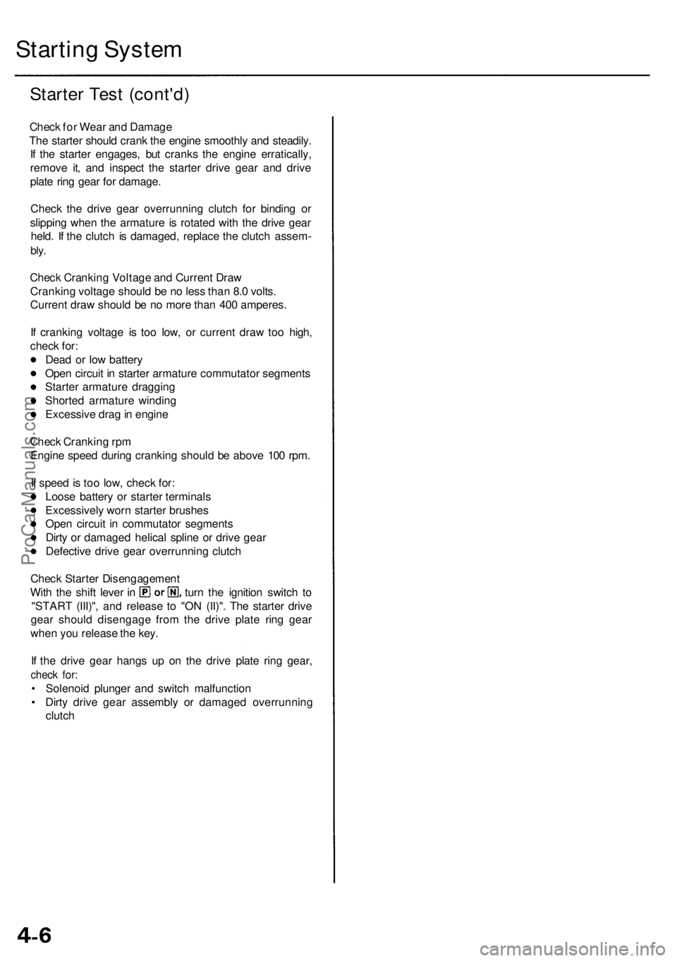
Starting Syste m
Starte r Tes t (cont'd )
Check fo r Wea r an d Damag e
Th e starte r shoul d cran k th e engin e smoothl y an d steadily .
I f th e starte r engages , bu t crank s th e engin e erratically ,
remov e it , an d inspec t th e starte r driv e gea r an d driv e
plat e rin g gea r fo r damage .
Chec k th e driv e gea r overrunning clutch fo r bindin g o r
slippin g whe n th e armatur e is rotate d wit h th e driv e gea r
held . I f th e clutc h i s damaged , replac e th e clutc h assem -
bly.
Chec k Crankin g Voltag e an d Curren t Dra w
Crankin g voltag e shoul d b e n o les s tha n 8. 0 volts .
Curren t draw shoul d b e n o mor e tha n 40 0 amperes .
I f crankin g voltag e i s to o low , o r curren t draw too high ,
chec k for :
Dea d o r lo w batter y
Ope n circui t i n starte r armatur e commutato r segment s
Starte r armatur e draggin g
Shorte d armatur e windin g
Excessiv e dra g in engin e
Chec k Crankin g rp m
Engin e spee d durin g crankin g shoul d b e abov e 10 0 rpm .
I f spee d is to o low , chec k for :
Loos e batter y o r starte r terminal s
Excessivel y wor n starte r brushe s
Ope n circui t i n commutato r segment s
Dirt y o r damage d helica l splin e o r driv e gea r
Defectiv e driv e gea r overrunnin g clutc h
Chec k Starte r Disengagemen t
With th e shif t leve r i n tur n th e ignitio n switc h t o
"STAR T (III)" , an d releas e t o "O N (II)" . Th e starte r driv e
gea r shoul d disengag e fro m th e driv e plat e rin g gea r
whe n yo u releas e th e key .
I f th e driv e gea r hang s u p o n th e driv e plat e rin g gear ,
check for :
• Solenoi d plunge r an d switc h malfunctio n
• Dirt y driv e gea r assembl y o r damage d overrunnin g
clutc h
ProCarManuals.com
Page 334 of 1954

Planetary Gear Inspection
Check if the planetary gears are worn or damaged. If they
are, also check the condition of the armature shaft gear
and ring gear.
ARMATURE
SHAFT GEAR
RING
GEAR
PLANETARY GEARS
Overrunning Clutch Inspection
Slide the overrunning clutch along the shaft.
Does it move freely? If not, replace it.
1.
2.
Rotate the overrunning clutch both ways.
Does it lock in one direction and rotate smoothly in
reverse? If it does not lock in either direction or it
locks in both directions, replace it.
SHAFT
3.
4.
DRIVE GEAR
If the starter drive gear is worn or damaged, replace
the overrunning clutch assembly; the gear is not avail-
able separately.
Check the condition of the torque converter ring gear
if the starter drive gear teeth are damaged.ProCarManuals.com
Page 371 of 1954

39. Disconnect the compressor clutch connector, then
remove the A/C compressor. Do not disconnect the
A/C hoses.
COMPRESSOR CLUTCH
CONNECTOR
A/C COMPRESSOR
8 x
1.25
mm
22 N-m (2.2 kgf-m,
16 Ibf-ft)
40. Disconnect the vehicle speed sensor (VSS) connector,
then remove the VSS/power steering speed sensor.
Do not disconnect the fluid hoses.
6 x 1.0 mm
12 N-m (1.2 kgf-m,
8.7 Ibf-ft)
VSS CONNECTOR
VSS/POWER STEERING
SPEED SENSOR
41. Remove the transmission stop collars.
42. Remove exhaust pipe A.
GASKETS
Replace.
GASKET
Replace.
EXHAUST
PIPE A
SELF-LOCKING NUT
10 x
1.25
mm
54 N-m (5.5 kgf-m,
40 Ibf-ft)
Replace.
10 x
1.25
mm
38 N-m (3.9 kgf-m,
28 Ibf-ft)
SELF-LOCKING NUT
10 x
1.25
mm
54 N-m (5.5 kgf-m,
40 Ibf-ft)
Replace.
TRANSMISSION STOP
COLLAR
43. Remove the wire harness cover and grommet, then
remove the three way catalytic converter (TWC).
SELF-LOCKING NUT
10 x
1.25
mm
33 N-m (3.4 kgf-m,
25 Ibf-ft)
Replace.
GROMMET
WIRE HARNESS
COVER
GASKET
Replace.
TWC
6 x 1.0 mm
9.8 N-m (1.0 kgf-m,
7.2 Ibf-ft)
SELF-LOCKING NUT
8 x
1.25
mm
22 N-m (2.2 kgf-m, 16 Ibf-ft)
Replace.ProCarManuals.com
Page 616 of 1954

(From pag e 11-116 )
I s ther e a clickin g nois e fro m
th e A/ C compresso r clutch ?
NO
YE S
Chec k fo r a n ope n i n th e wir e(ACC line) :Momentaril y connec t th e A/ C
clutc h rela y connecto r termina l
No. 4 to bod y groun d wit h ajumpe r wir e severa l times .
A/C CLUTC H RELA Y CONNECTO R (C344 )
Wire sid e o f
femal e terminal s
I s ther e a clickin g nois e fro m
th e A/ C compresso r clutch ? Se
e ai r conditione r inspectio n
(se e sectio n 22 ).
YE S
Repai r ope n in th e wir e betwee n
th e PC M (A8 ) an d th e A/ C clutc h
relay.
PCM CONNECTOR S
Check th e A/ C operation :
1 . Star t th e engine .
2 . Tur n th e blowe r switc h ON .
3 . Tur n th e A/ C switc h ON .
Doe s th e A/ C operate ?
YES
Chec k fo r a n ope n i n th e wir e
(AC S line) :
Measur e voltag e betwee n PC M
connecto r terminal s A2 6 an d C2 .
Ai r conditionin g signa l i s OK . Wir
e sid e o f femal e terminal s
I s voltag e les s tha n 1. 0 V ?
YE S
Repai r ope n in th e wir e betwee n
th e PC M (C2 ) an d th e radiato r fa n
contro l unit .
— Substitut e a known-goo d PC M
an d rechec k (se e pag e 11-42
fo r immobilize r information) .
I f symptom/indicatio n goe s
away , replac e th e origina l PCM .
— Se e th e ai r conditione r inspec -
tio n (se e sectio n 22 ).N O
NO
ProCarManuals.com
Page 711 of 1954
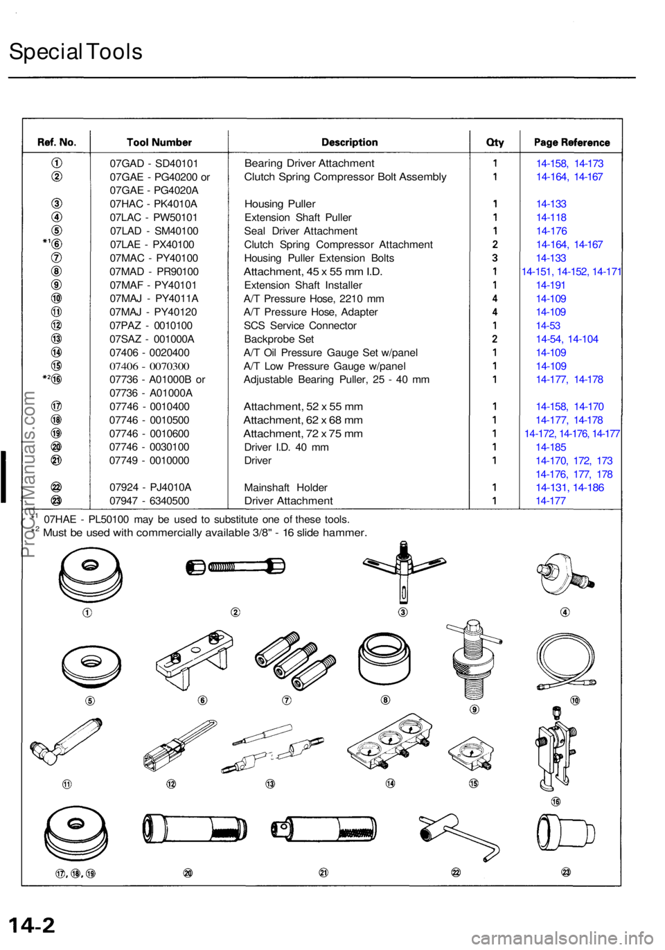
Special Tool s
07GA D - SD4010 1
07GA E - PG4020 0 o r
07GA E - PG4020 A
07HA C - PK4010 A
07LA C - PW5010 1
07LA D - SM4010 0
07LA E - PX4010 0
07MA C - PY4010 0
07MA D - PR9010 0
07MA F - PY4010 1
07MA J - PY4011 A
07MA J - PY4012 0
07PA Z - 001010 0
07SA Z - 001000 A
0740 6 - 002040 0
07406 - 007030 0
07736 - A01000 B o r
0773 6 - A01000 A
0774 6 - 001040 0
0774 6 - 001050 0
0774 6 - 001060 0
0774 6 - 003010 0
0774 9 - 001000 0
0792 4 - PJ4010 A
0794 7 - 634050 0
Bearing Drive r Attachmen t
Clutch Sprin g Compresso r Bol t Assembl y
Housing Pulle r
Extensio n Shaf t Pulle r
Sea l Drive r Attachmen t
Clutc h Sprin g Compresso r Attachmen t
Housin g Pulle r Extensio n Bolt s
Attachment , 4 5 x 5 5 m m I.D .
Extensio n Shaf t Installe r
A/ T Pressur e Hose , 221 0 m m
A/ T Pressur e Hose , Adapte r
SC S Servic e Connecto r
Backprob e Se t
A/ T Oi l Pressur e Gaug e Se t w/pane l
A/ T Lo w Pressur e Gaug e w/pane l
Adjustable Bearing Puller , 2 5 - 4 0 m m
Attachment , 5 2 x 5 5 m m
Attachment , 6 2 x 6 8 m m
Attachment , 7 2 x 7 5 m m
Drive r I.D . 4 0 m m
Drive r
Mainshaf t Holde r
Driver Attachmen t
14-158, 14-17 3
14-164 , 14-16 7
14-13 3
14-11 8
14-17 6
14-164 , 14-16 7
14-13 3
14-151 , 14-152 , 14-17 1
14-19 1
14-10 9
14-10 9
14-53
14-54 , 14-10 4
14-10 9
14-10 9
14-177 , 14-17 8
14-158 , 14-17 0
14-177 , 14-17 8
14-172 , 14-176 , 14-17 7
14-185
14-170 , 172 , 17 3
14-176 , 177 , 17 8
14-131 , 14-18 6
14-177
*
1 07HA E - PL5010 0 ma y b e use d t o substitut e on e o f thes e tools .
*2 Must b e use d wit h commerciall y availabl e 3/8 " - 1 6 slid e hammer .
ProCarManuals.com