1996 ACURA RL KA9 tire pressure
[x] Cancel search: tire pressurePage 712 of 1954

Description
The automatic transmission is a combination of a 3-element torque converter and a dual-shaft electronically controlled
automatic transmission which provides 4 speeds forward and 1 reverse. The entire unit is positioned in line with the engine.
Torque Converter, Gears and Clutches
The torque converter consists of a pump, turbine and stator, assembled in a single unit. They are connected to the engine
crankshaft so they turn together as a unit as the engine turns. Around the outside of the drive plate is a ring gear which
meshes with the starter pinion when the engine is being started.
The entire torque converter assembly serves as a flywheel while transmitting power to the transmission mainshaft.
The transmission has two parallel shafts: the mainshaft and the countershaft. The mainshaft is in line with the engine
crankshaft. The mainshaft includes the 1st, 4th and 2nd clutches and gears for 4th, 1st, 2nd and reverse (3rd gear is integral
with the mainshaft). The countershaft includes the 3rd, 1st-hold and reverse clutches, and gears for 3rd, 4th, 1st, 2nd,
reverse and park. The secondary drive gear is integrated with the countershaft. The gears on the mainshaft are in constant
mesh with those on the countershaft. When certain combinations of gears in the transmission are engaged by clutches,
power is transmitted from the mainshaft to the countershaft to provide , , , and positions.
Electronic Control
The electronic control system consists of a Powertrain Control Module (PCM), sensors, a A/T clutch pressure control solenoid
and four solenoid valves. Shifting and lock-up are electronically controlled for comfortable driving under all conditions.
The PCM is located below the dashboard, under the front lower panel on the passenger's side.
Hydraulic Control
The lower valve body assembly includes the main valve body, the secondary valve body, the throttle valve body, the
solenoid, the shift solenoid valves and the ATF passage body. They are bolted on the lower part of the transmission hous-
ing. Other valve bodies, the regulator valve body, the ATF pump body and the accumulator body, are bolted to the torque
converter housing.
The main valve body contains the manual valve, the 1-2 shift valve, the 2-3 shift valve, the 3-4 shift valve, the 4-3 kick-down
valve and the main orifice control valve. The secondary valve body contains the 3-4 orifice control valve, the 4-3 shift timing
valve, the line pressure control valve, the modulator valve and the accumulator pistons. The throttle valve body includes
the throttle valve which is bolted onto the secondary valve body. The A/T clutch pressure control solenoid is joined to the
throttle valve body. The regulator valve body contains the regulator valve, the lock-up shift valve and the cooler relief valve.
Fluid from the regulator passes through the manual valve to the various control valves. The ATF pump body contains the
lock-up timing valve, the lock-up control valve and the relief valve. The torque converter check valve is located in the torque
converter housing under the ATF pump body. The accumulator body contains the accumulator pistons. The reverse accu-
mulator and the 1st-hold accumulator pistons are assembled in the rear cover.
The 1st, 1st-hold, 2nd and reverse clutches receive fluid from their respective feed pipes, and the 3rd and 4th clutches
receive fluid from the internal hydraulic circuit.
Shift Control Mechanism
Input from various sensors located throughout the vehicle determines which shift solenoid valve the PCM will activate.
Activating a shift solenoid valve changes modulator pressure, causing a shift valve to move. This pressurizes a line to one
of the clutches, engaging the clutch and its corresponding gear.
Lock-up Mechanism
In position, in 2nd, 3rd, and 4th, and position in 3rd, pressurized fluid is drained from the back of the torque con-
verter through a fluid passage, causing the lock-up piston to be held against the torque converter cover. As this takes
place, the mainshaft rotates at the same speed as the engine crankshaft. Together with hydraulic control, the PCM opti-
mizes the timing of the lock-up mechanism. The lock-up valves control the range of lock-up according to torque converter
clutch (lock-up control) solenoid valves A and B, and throttle valve. When torque converter clutch (lock-up control)
solenoid valves A and B activate, modulator pressure changes. The torque converter clutch (lock-up control) solenoid
valves A and B are mounted on the torque converter housing, and are controlled by the PCM.ProCarManuals.com
Page 1026 of 1954

Wheel Alignment
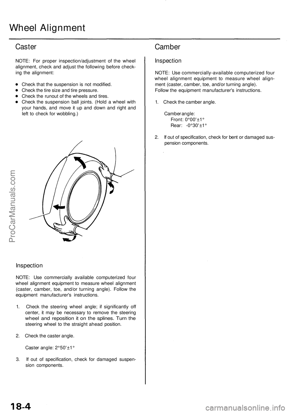
Caster
NOTE: For proper inspection/adjustment of the wheel
alignment, check and adjust the following before check-
ing the alignment:
Check that the suspension is not modified.
Check the tire size and tire pressure.
Check the runout of the wheels and tires.
Check the suspension ball joints. (Hold a wheel with
your hands, and move it up and down and right and
left to check for wobbling.)
Inspection
NOTE: Use commercially available computerized four
wheel alignment equipment to measure wheel alignment
(caster, camber, toe, and/or turning angle). Follow the
equipment manufacturer's instructions.
1. Check the steering wheel angle; if significantly off
center, it may be necessary to remove the steering
wheel and reposition it on the splines. Turn the
steering wheel to the straight ahead position.
2. Check the caster angle.
Caster angle: 2°50'±1°
3. If out of specification, check for damaged suspen-
sion components.
Camber
Inspection
NOTE: Use commercially-available computerized four
wheel alignment equipment to measure wheel align-
ment (caster, camber, toe, and/or turning angle).
Follow the equipment manufacturer's instructions.
1. Check the camber angle.
Camber angle:
Front: 0°00'±1°
Rear: -0°30'±1°
2. If out of specification, check for bent or damaged sus-
pension components.ProCarManuals.com
Page 1027 of 1954

Front Toe Inspection/Adjustment
NOTE: Use commercially-available computerized four
wheel alignment equipment to measure wheel align-
ment (caster, camber, toe, and/or turning angle).
Follow the equipment manufacturer's instructions.
1. Check the tire pressure.
2. Center the steering wheel spokes.
3. Check the toe with the wheels pointed straight
ahead.
Front toe: 0 ± 2 mm (0±1/16 in)
— If adjustment is required, go on to step 4.
— If no adjustment is required, remove the align-
ment equipment.
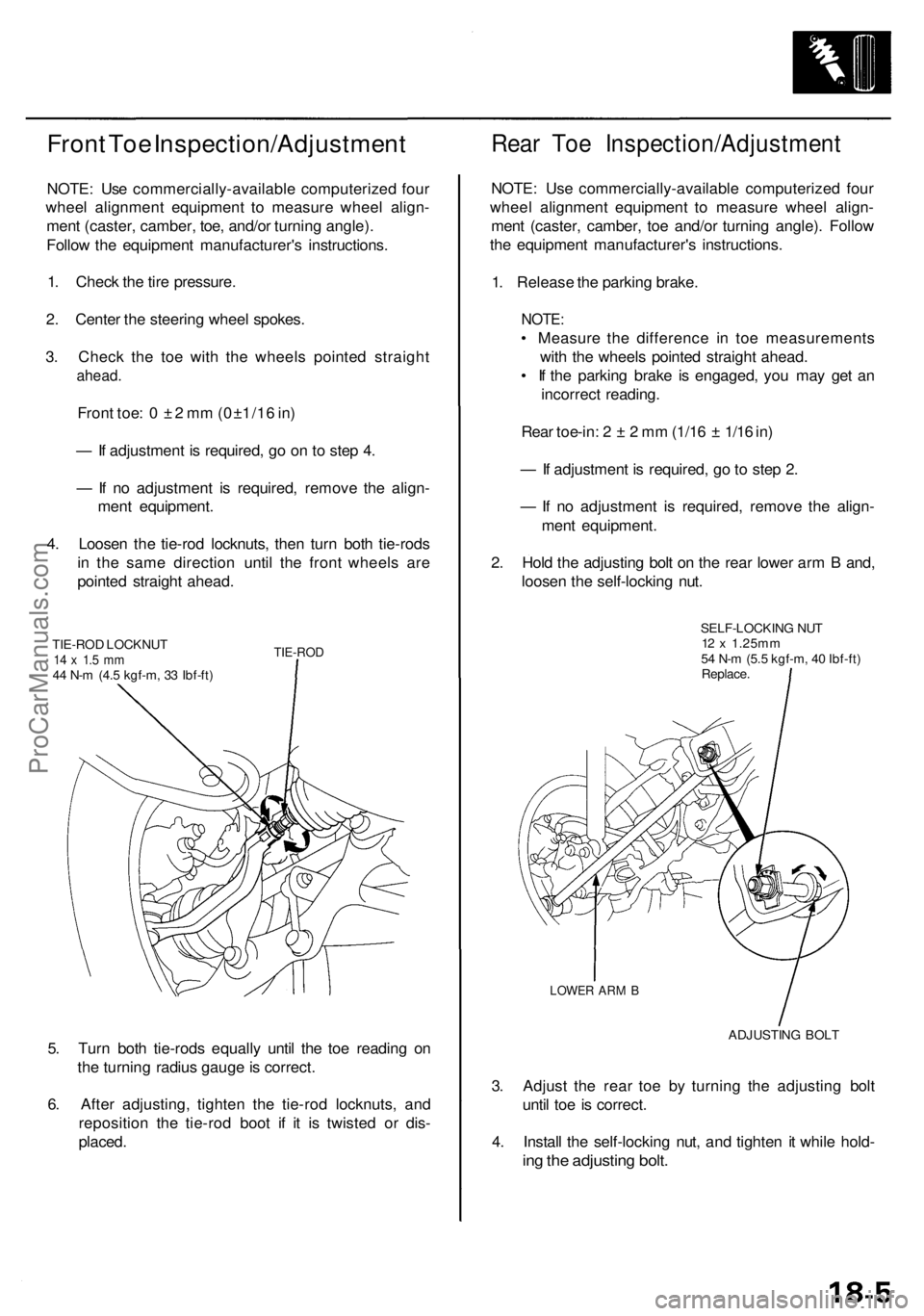
4. Loosen the tie-rod locknuts, then turn both tie-rods
in the same direction until the front wheels are
pointed straight ahead.
TIE-ROD LOCKNUT
14 x 1.5 mm
44 N-m (4.5 kgf-m, 33 Ibf-ft)
TIE-ROD
5. Turn both tie-rods equally until the toe reading on
the turning radius gauge is correct.
6. After adjusting, tighten the tie-rod locknuts, and
reposition the tie-rod boot if it is twisted or dis-
placed.
Rear Toe Inspection/Adjustment
NOTE: Use commercially-available computerized four
wheel alignment equipment to measure wheel align-
ment (caster, camber, toe and/or turning angle). Follow
the equipment manufacturer's instructions.
1. Release the parking brake.
NOTE:
• Measure the difference in toe measurements
with the wheels pointed straight ahead.
• If the parking brake is engaged, you may get an
incorrect reading.
Rear toe-in: 2 ± 2 mm (1/16 ± 1/16 in)
— If adjustment is required, go to step 2.
— If no adjustment is required, remove the align-
ment equipment.
2. Hold the adjusting bolt on the rear lower arm B and,
loosen the self-locking nut.
SELF-LOCKING NUT
12 x 1.25mm
54 N-m (5.5 kgf-m, 40 Ibf-ft)
Replace.
LOWER ARM B
ADJUSTING BOLT
3. Adjust the rear toe by turning the adjusting bolt
until toe is correct.
4. Install the self-locking nut, and tighten it while hold-
ing the adjusting bolt.ProCarManuals.com
Page 1197 of 1954

Troubleshooting Precautions
1. In any of these cases, the TCS indicator light may come on or stay on even the TCS system is normal.
The coolant temperature is 32°F (0°C) or below.
The parking brake is applied for more than 30 seconds while the vehicle is being driven.
The tires are not inflated to the specified pressure.
The wheel sensor signal is interrupted during driving at speeds of 6 mph (10 km/h) or above due to, for example, a
vehicle spinning.
The MAP sensor, the coolant temperature sensor, the ICM or the atmospheric pressure sensor system of the PGM-FI
system is faulty.
2. TCS does not function when the TCS indicator light is ON.
3. When both the TCS indicator light and the MIL are ON, troubleshoot the PGM-FI system first.
4. When both the TCS indicator light and the ABS indicator light are ON, troubleshoot the ABS first.
5. The DTC 4-9 (ABS down) is memorized when the ABS control unit cannot output the wheel speed signal due to, for
example, a missing or blown ABS B2 (15 A) fuse. If you fail to erase the DTC of the TCS after troubleshooting the ABS,
the DTC remains in the TCS control unit memory. Therefore, be sure to test-drive the vehicle, and check the TCS indica-
tor light before starting to troubleshoot the TCS.ProCarManuals.com
Page 1742 of 1954

Troubleshooting Precaution s
General Operatio n
Refer t o th e Acur a Navigatio n Syste m Owner' s Manua l fo r th e navigatio n syste m operatin g procedures .
Anti-thef t Featur e
Th e navigatio n syste m ha s a code d thef t protectio n circuit . B e sur e t o ge t th e customer' s four-digi t securit y cod e numbe r
before ;
• disconnectin g th e batter y
• disconnectin g th e navigatio n uni t connecto r
• removin g th e BACK-UP/RADI O (7. 5 A ) fus e fro m th e under-hoo d fuse/rela y bo x
Afte r service , reconnec t powe r t o th e navigatio n unit , an d tur n th e ignitio n switc h O N (II) . Ente r th e 4-digi t securit y code ,
then selec t "Done" . Whe n replacin g th e navigatio n unit , b e sur e to giv e th e custome r th e ne w anti-thef t securit y code .
Sympto m Diagnosi s
Certain circumstance s an d syste m limitation s wil l produc e occasiona l vehicl e positionin g errors . Som e customer s ma y
thin k thi s indicate s a proble m wit h th e navigatio n syste m when , i n fact , th e syste m is normal . Kee p th e followin g item s i n
min d whe n interviewin g customer s abou t navigatio n syste m symptoms .
Self-lnertia l Navigatio n Limitation s
Th e limitation s o f th e self-inertia l portio n o f th e navigatio n syste m (th e ya w rat e senso r an d th e vehicl e spee d sensor ) can
caus e som e discrepancie s betwee n th e actua l vehicl e positio n an d th e indicate d vehicl e position . I f ther e i s a larg e dis -
crepancy , an d th e syste m is receivin g GP S signals , th e syste m wil l adjus t th e indicate d vehicl e positio n to th e GP S vehicl e
position . However , i f GP S signal s canno t b e received , yo u mus t tun e th e vehicl e positio n manually .
Th e followin g circumstance s ma y caus e vehicl e positionin g error s unti l th e syste m ca n adjus t t o th e GPS .
• Movin g th e vehicl e wit h th e engin e stopped , suc h a s b y ferr y o r to w truck , o r i f th e vehicl e is spu n o n a tur n table .
• Tir e slippage , change s i n tir e rollin g diameters , an d som e drivin g situation s ma y caus e discrepancie s i n trave l dis -
tances . Example s o f thi s include :
— Continuou s tir e slippag e o n a slipper y surface .
— Drivin g wit h sno w chain s mounted .
— Abnorma l tir e pressures .
— Differen t diamete r tires .
— Frequen t lane s change s acros s a wid e highway .
— Continuou s drivin g o n a straigh t o r gentl y curvin g highway .
• Tolerance s i n th e syste m an d ma p accurac y sometime s limi t ho w precisel y th e vehicl e positio n is indicated .
Example s o f thi s include :
— Drivin g o n road s no t show n o n th e ma p (ma p matchin g is no t possible) .
— Drivin g o n a roa d tha t wind s in on e direction , suc h a s a loo p bridge , a n interchange , o r a spira l parkin g garage .
— Drivin g o n a roa d wit h a serie s o f shar p hair-pi n turns .
— Drivin g o n on e o f tw o clos e paralle l roads .
— Afte r makin g man y 9 0 degre e turns .
ProCarManuals.com