1996 ACURA RL KA9 trunk
[x] Cancel search: trunkPage 32 of 1954

Cavity Wire
Test condition
Test: Desired result
Possible cause if result is not obtained
6
5
4
2
3
1
7
YEL/BLK
YEL
PNK/BLU
GRN
RED/WHT
BLK
WHT
Jump to ground
Ignition switch ON (II)
Jump to ground
Jump to ground
Jump to ground
Under all conditions
Under all conditions
The horn should sound.
Check for voltage to ground:
There should be battery voltage.
The trunk should open.
The doors should unlock.
If all doors are closed, the doors
should lock.
Check for continuity to ground:
There should be continuity.
Check for voltage to ground:
There should be battery voltage.
• Blown No. 44 (20 A) fuse in the
under-hood fuse/relay box
• Faulty multiplex control unit
(passenger's)
• Faulty horn
• An open in the wire
• Blown No. 13 (7.5 A) fuse in the
under-dash fuse/relay box
• An open in the wire
• Blown No. 44 (20 A) fuse in the
under-hood fuse/relay box
• Faulty multiplex control unit
(passenger's)
• Faulty trunk lid opener
• An open in the wire
• Blown No. 44 (20 A) fuse in the
under-hood fuse/relay box
• Faulty multiplex control unit
(passenger's)
• An open in the wire
• Blown No. 44 (20 A) fuse in the
under-hood fuse/relay box
• Faulty multiplex control unit
(passenger's)
• An open in the wire
• Poor ground (G602)
• An open in the wire
• Blown No. 44, (20 A) fuse in the
under-hood fuse/relay box
• An open in the wireProCarManuals.com
Page 214 of 1954
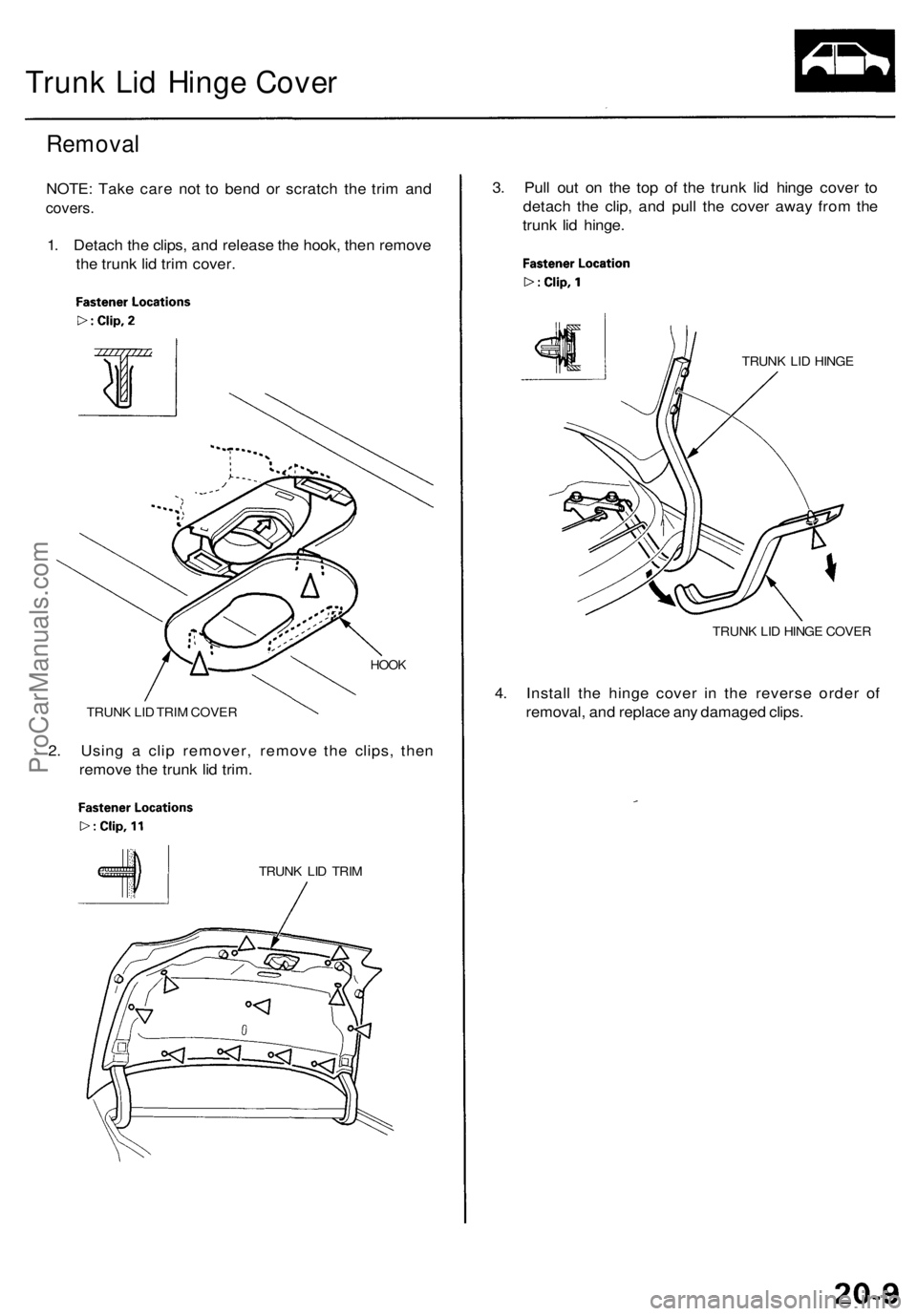
Trunk Lid Hinge Cover
Removal
NOTE: Take care not to bend or scratch the trim and
covers.
1. Detach the clips, and release the hook, then remove
the trunk lid trim cover.
HOOK
TRUNK LID TRIM COVER
2. Using a clip remover, remove the clips, then
remove the trunk lid trim.
TRUNK LID TRIM
3. Pull out on the top of the trunk lid hinge cover to
detach the clip, and pull the cover away from the
trunk lid hinge.
TRUNK LID HINGE
TRUNK LID HINGE COVER
4. Install the hinge cover in the reverse order of
removal, and replace any damaged clips.ProCarManuals.com
Page 229 of 1954

Navigation Syste m
Genera l Troubleshootin g Informatio n
General Operatio n
Refer t o th e Acur a Navigatio n Syste m Owner' s manua l
fo r th e navigatio n syste m operatin g procedures .
Anti-theft Featur e
The navigatio n syste m ha s a code d thef t protectio n cir -
cuit . B e sur e t o ge t th e customer' s 4-digi t securit y cod e
numbe r before :
• disconnectin g th e batter y
• disconnectin g th e navigatio n uni t 8 P connecto r
• removin g th e No . 5 6 (7.5A ) fus e fro m th e under-hoo d
fuse/rela y bo x
Afte r service , reconnec t powe r t o th e navigatio n unit ,
an d tur n th e ignitio n switc h O N (II) . Ente r th e 4-digi t
securit y code , the n selec t "Done" .
I f th e cod e canno t b e found , us e th e interactiv e Networ k
( iN ) t o loo k i t up . Yo u wil l nee d th e seria l numbe r fo r
th e navigatio n uni t i n th e trunk . I t i s o n a ta g o n th e
undersid e o f th e unit . Alternatively , yo u ca n vie w th e
seria l numbe r i n on e o f th e Nav i EC U diagnosti c
screens.
When replacin g th e navigatio n unit , b e sur e t o giv e th e
custome r th e ne w anti-thef t securit y code .
Sympto m Diagnosi s
Under som e circumstances , th e navigatio n syste m ma y
behav e in a n inconsisten t manner . Som e customer s ma y
thin k tha t thi s indicate s a proble m when , i n fact , th e
syste m is workin g properly . Kee p th e followin g item s i n
min d whe n interviewin g customer s abou t symptom s
o f th e navigatio n system .
Self-lnertia l Navigatio n Limitation s
When GP S signal s canno t b e receive d (lik e in a tunne l o r
i n a n urba n environmen t o f tal l buildings) , th e syste m is
totall y dependan t o n th e ya w rat e an d spee d senso r t o
positio n th e vehicl e o h th e map . Unde r thes e circum -
stance s smal l error s i n th e ya w rat e an d spee d senso r
ca n accumulat e an d displa y th e vehicl e positio n o n a n
adjacen t street , o r laggin g behin d th e actua l position .
Thi s i s normal , an d usuall y correct s itsel f onc e sate -
llit e receptio n is re-established .
Th e followin g circumstance s ma y cause s vehicl e posi -
tionin g errors . •
Movin g th e vehicl e wit h th e navigatio n syste m o n an d
th e vehicl e stopped , suc h a s b y ferr y o r to w truck , o r i f
th e vehicl e is spu n o n a tur n tabl e
• Tir e slippage , change s i n tir e rollin g diameters , an d
som e drivin g situation s ma y caus e discrepancie s i n
trave l distances . Example s o f thi s include :
- Continuou s tir e slippag e o n a slipper y surfac e
- Drivin g wit h sno w chain s mounte d
-Abnorma l tir e pressur e
- Incorrec t tir e siz e
- Frequen t lan e change s acros s a wid e highwa y
-Continuou s drivin g o n a straigh t o r gentl y curvin g
highwa y
• Tolerance s i n th e syste m an d ma p inaccuracie s some -
times limi t ho w precisel y th e vehicl e positio n i s indi -
cated . Example s o f thi s include :
- Drivin g o n road s no t show n o n th e ma p (ma p match -
in g i s no t possible )
- Drivin g o n a roa d tha t wind s i n on e direction , suc h a s
a loo p bridge , a n interchange , o r a spira l parkin g
garage
-Drivin g o n a roa d wit h a serie s o f shar p hair-pi n
turn s
- Drivin g nea r a gradua l highwa y exi t o r transitio n
- Drivin g o n on e o f tw o close paralle l road s
- Makin g man y 9 0 degre e turn s
Globa l Positionin g Syste m (GPS ) Limitation s
The GP S canno t detec t th e vehicle' s positio n durin g th e
followin g instances :
• Fo r th e firs t 5 to 1 0 minute s afte r reconnectin g th e bat -
ter y (thi s ca n tak e a s lon g a s 4 5 minutes )
• Whe n th e satellit e signal s ar e blocke d b y tal l building ,
mountains , tunnels , larg e trees , o r larg e truck s
• Whe n ther e i s n o satellit e signa l outpu t (Signa l outpu t
i s sometime s stoppe d fo r satellit e servicing )
• Whe n th e satellit e signal s ar e blocke d b y th e operatio n
of som e electroni c aftermarke t accessorie s including ,
but no t limite d t o non-DE M in-das h entertainmen t
unit s (radio , C D players/changers , an d L o Jack ) an d
windo w tintin g abov e th e GP S antenn a
Th e accurac y o f GP S is reduce d durin g thes e instances :
• Whe n onl y tw o satellit e signal s ca n b e receive d (Thre e
satellit e signal s ar e require d fo r accurat e positioning )
• Whe n th e satellit e contro l center s ar e experiencin g
problem s
• Whe n drivin g hea r hig h tensio n powe r lines .
• Whe n drivin g nea r tal l building s tha t reflec t satellit e
signals , creatin g fals e positio n locatio n readings .
• I f electroni c GP S jammin g i s occurrin g eithe r inten -
tionally , o r unintentionally .
• I f loos e item s o r pet s ar e restin g abov e th e antenn a
o n th e rea r shelf .
ProCarManuals.com
Page 247 of 1954

Navigation Syste m
System Descriptio n (cont'd )
Item
MW
Nav i
Off Rout e
Outlyin g Area s
PC Car d Slo t
PCM
PCMCI A
PIN
PO I
Polygo n
QWERT Y
SCS connecto r
Security Cod e
Touc h Switche s o r Touc h
Senso r
Tuning
Unverifie d Street s
On-Sta r
Satellite Radi o (X M Radio )
Definitio n
Maneuve r Window . Whil e on-rout e to a destination , thi s windo w display s informatio n
about th e nex t maneuver .
Abbreviatio n fo r th e Navigatio n Syste m
This occur s whe n th e use r leave s mappe d roads . Of f roa d trackin g dot s ("breadcrumbs" )
are displaye d if th e optio n is enable d in Setup . Th e use r ca n us e the m to retur n t o a
mappe d road . Th e botto m o f th e navigatio n scree n wil l sa y "No t o n a digitize d road "
These ar e rura l area s tha t typicall y hav e onl y their main road s mapped . Al l othe r road s
are show n in ligh t brow n fo r referenc e only , sinc e the y hav e no t bee n verified .
The P C Car d (PCMCIA , typ e II ) slo t i s fo r factor y us e only . Mak e sur e tha t th e slidin g doo r
is close d a t al l items , i f opened , a n erro r messag e is displaye d o n th e screen .
Powertrai n Contro l Module . Thi s uni t supplie s th e navigatio n syste m spee d signal .
An compute r industr y define d ter m referrin g t o th e P C Car d slo t standard .
Personal Identificatio n Number , a rando m 4 digi t numbe r create d b y th e custome r t o pro -
tect persona l informatio n
Point O f Interest . Thes e ar e th e businesses , school s etc . foun d unde r th e "places " optio n
on th e mai n men u
Colore d area s o n th e ma p scree n denotin g parks , school s etc . Se e th e Navigatio n
Owner's Manua l "Travelin g t o You r Destination " fo r a lis t o f th e assigne d colors .
Keyboar d layou t resemblin g th e typewrite r keys . Th e keyboar d layou t ca n b e change d t o
a n alphabetica l layou t i n th e Setu p mode .
The 2-pi n connecto r use d t o pu t th e navigatio n syste m int o th e diagnosti c mod e
Code neede d to activat e th e navigatio n system . Th e securit y cod e ca n b e obtaine d fro m
the "IN " b y enterin g th e navigatio n syste m contro l seria l number . Th e seria l numbe r ca n
be foun d fro m th e diagnosti c screen s (Uni t Check , Nav i ECU) , o r fro m th e unde r sid e o f
the contro l unit .
The side s o f th e navigatio n scree n hav e 9 vertica l an d 2 0 horizonta l infrare d beam s tha t
are interrupte d b y th e user' s finge r t o selec t th e desire d function .
A continua l updat e o f interna l navigatio n syste m scalin g factors . Se e th e individua l sen -
sor tunin g discussion s unde r eithe r "Syste m Description" , o r "Syste m Diagnosi s Mode "
(see pag e 23-40 ) i n thi s manual .
These street s hav e no t bee n verifie d fo r tur n restrictions , one-way , etc . The y ar e show n i n
ligh t brow n o n th e map . Yo u ca n ente r addres s destination s i n thes e areas , bu t voic e
guidanc e end s a t th e las t verifie d stree t closes t t o you r destination .
This uni t provide s emergency , an d othe r specialt y service s ove r a cellula r link . Ther e is a
monthl y charg e associate d wit h thi s feature . Th e uni t ha s it' s ow n GP S antenna , an d cel -
lula r phon e antenna . Whe n in use , th e navigatio n guidanc e is muted , an d voic e contro l
system is disabled .
XM Radi o fo r thi s model . Thi s provide s additiona l channel s o f audi o entertainmen t fo r a
fee . Th e X M radi o receive r i s locate d in th e trunk , an d ha s it s ow n independen t satellite ,
and terrestria l antenna s (fo r receivin g th e broadcast s whe n satellit e signal s ar e temporari -
ly blocked) .
ProCarManuals.com
Page 265 of 1954

Navigation Syste m
System Diagnosi s Mod e
Start-u p procedur e an d Diagnosi s Men u
There ar e tw o way s t o ente r th e diagnosti c mode :
1 . Connec t th e SC S connecto r (se e ste p 2 o n pag e
23-52 ) t o th e navigatio n servic e connecto r focate d
i n th e trunk . Tur n th e ignitio n switc h t o th e O N (II )
position . Th e displa y wil l g o directl y t o th e diagnosti c
men u scree n show n below .
Note : whe n finishe d troubleshooting , mak e sur e t o
remov e th e SC S connector !
2 . Tur n th e ignitio n switc h t o th e O N (II ) position .
Us e th e navigatio n displa y har d button s a s describe d
below :
A . I f th e batter y ha s no t bee n disconnected , the n
pres s an d hol d th e 3 button s (Menu , Map/Guide ,
an d Cancel) , an d kee p the m presse d fo r
approximatel y 5 seconds . Th e displa y scree n wil l
g o directl y t o th e "Selec t Diagnosi s Items " men u
show n below .
B . I f th e batter y wa s disconnecte d an d reconnecte d
prio r t o thi s test , hol d dow n th e Men u an d Zoo m
Ou t button s a t th e "Code " o r "GP S Acquire "
screen . Th e displa y wil l g o t o th e "Nav i Syste m
Link " screen . Pus h th e joystic k t o g o to th e
"Functiona l Setu p menu, " the n touc h th e Retur n
icon t o ge t t o th e "Selec t Diagnosi s Items " menu .
Note : Thi s onl y allow s acces s t o th e diagnosti c
screens . Al l othe r navigatio n function s ar e
disabled .
DIAGNOSI S MEN U SCREE N
After th e displa y change s t o th e Selec t Diagnosi s Item s
menu , touc h th e ite m yo u wan t t o chec k an d th e chec k
wil l start . T o retur n t o th e previou s screen , touc h
"RETURN" .
• Nav i Syste m
(Link)
• Monito r Chec k
• Uni t Chec k •
Ca r Statu s
• GP S
Informatio n
• Ya w Rat e
• Tir e Calibrat e
• Functiona l
Setu p
• Versio n
Navi Syste m Lin k
• Thi s diagnosti c test s th e cable s connectin g th e navi -
gation components . Ensur e tha t th e ignitio n switc h is
in th e O N (II ) position . Whe n th e diagnosti c begins , a
"bong " soun d i s heard . Th e syste m is i n a
"Detecting " mode , an d i s waitin g fo r al l item s i n
whit e t o b e tested . Thi s include s th e voic e contro l
switch , an d microphone . Pres s th e TAL K butto n o n
th e voic e contro l switch , an d in a norma l voice , sa y
"testing" . Th e Tal k indicato r o n th e scree n shoul d
becom e green , an d th e voic e leve l indicato r shoul d
mov e to th e 6
th ba r t o pass . Next , pres s th e BAC K
button . Thi s shoul d caus e th e Cance l indicato r t o g o
green .
• I f al l o f th e communicatio n line s connectin g th e
syste m components , an d th e voic e contro l
switch/microphon e chec k ou t O K (al l bloc k dia -
gra m item s green) , the n th e O K indicato r wil l
becom e green .
• I f ther e i s a proble m wit h th e system , th e fault y
system componen t ite m wil l chang e to red , an d
the scree n wil l sho w "NG " i n red . Us e th e trou -
bleshootin g index , an d othe r diagnosti c screen s t o
hel p locat e th e problem .
• Th e indicatio n o n th e scree n wil l no t chang e unti l
th e ignitio n switc h i s cycled . Afte r repairin g th e
affecte d cabl e o r system , repea t thi s diagnostic .
NOTE : Green boxes an d gree n "OK " indicat e tha t
the communication s line s (cables ) ar e intact . Thi s
diagnosti c doe s no t necessaril y impl y tha t th e
individua l component s ar e functionin g properly .
Fo r instance , th e GP S antenn a wir e ma y b e
crushed , bu t stil l sho w a s "green" . A roa d test , o r
othe r diagnosti c ma y b e necessar y t o fin d th e
problem.
• Touc h th e Exi t Dia g ico n t o exit .
ProCarManuals.com
Page 278 of 1954
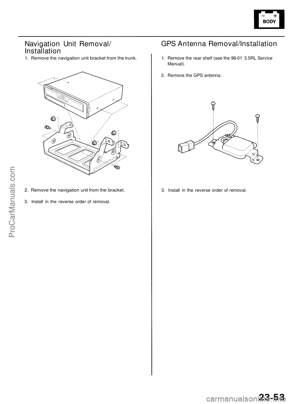
Navigation Unit Removal/
Installation
1. Remove the navigation unit bracket from the trunk.
2. Remove the navigation unit from the bracket.
3. Install in the reverse order of removal.
3. Install in the reverse order of removal.
GPS Antenna Removal/Installation
1. Remove the rear shelf (see the 96-01 3.5RL Service
Manual).
2. Remove the GPS antenna.ProCarManuals.com
Page 309 of 1954

Lubrication Points
For the details of lubrication points and types of lubricants to be applied, refer to the Illustrated Index and various work
procedures (such as Assembly/Reassembly, Replacement, Overhaul, Installation, etc.) contained in each section.
No.
1
2
3
4
5
6
7
8
9
10
11
12
13
14
15
16
17
18
19
20
21
22
LUBRICATION POINTS
Engine
Transmission
Brake line (Includes ABS line)
Power steering gearbox
Steering boots
Throttle cable end
Steering ball joints
Shift lever (Automatic transmission)
Pedal linkage
Intermediate shaft
Brake master cylinder pushrod
Fuel
fill
lid
Battery terminals
Trunk hinges and latch
Door hinges upper and lower
Door opening detents
Hood hinges and hood latch
Brake line joints (Front and rear wheelhouse)
Caliper Piston boot, caliper
Pins and boots
Power steering system
Differential
A/C compressor
API SERVICE LABEL API CERTIFICATION SEAL
LUBRICANT
API Service Grade: Use SJ "Energy Conserving" grade oil.
The oil container may also display the API Certification
seal shown below. Make sure it says "For Gasoline
Engines."
SAE Viscosity: See chart below.
Honda ATF-Z1 (ATF)*1
Genuine Honda DOT3 brake fluid*2
Steering grease P/N 08733 - B070E
Multi-purpose grease
Honda White Lithium Grease
Rust preventive
Silicone grease
Genuine Honda power steering fluid*3
Hypoid gear Oil API GL4 or GL5
Viscosity:
at above -18°C (0°F): SAE 90
at less than -18°C (0°F): SAE 80W-90
Compressor oil:
DENSO: ND-OIL8 (P/N) 38897 - PR7 - A01 AH or 38899 -
PR7-A01)
(For Refrigerant: HFC-134a (R-134a))
Recommended engine oil
viscosity for ambient
temperature ranges
*1: Always use Honda ATF-Z1 (ATF). Using a non-Honda ATF can affect shift quality.
*2: Always use Genuine Honda DOT3 Brake Fluid. Using a non-Honda brake fluid can cause corrosion and decrease the
life of the system.
*3: Always use Genuine Honda Power Steering Fluid. Using any other type of power steering fluid or automatic transmis-
sion fluid can cause increased wear and poor steering in cold weather.ProCarManuals.com
Page 1358 of 1954
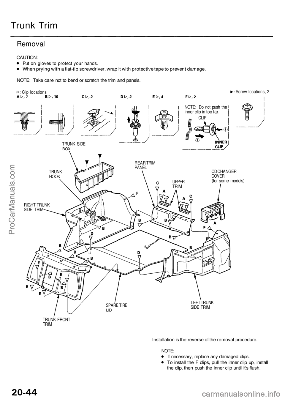
Trunk Tri m
Remova l
CAUTION :
Put o n glove s t o protec t you r hands .
When pryin g wit h a flat-ti p screwdriver , wra p it wit h protectiv e tap e to preven t damage .
NOTE : Tak e car e no t t o ben d o r scratc h th e tri m an d panels .
Clip location s Scre
w locations , 2
TRUN K SID E
BOX
TRUN KHOOK
RIGH T TRUN K
SID E TRI M NOTE
: D o no t pus h th e
inne r cli p in to o far .
CLI P
REA R TRI M
PANE L
CD CHANGE R
COVER(for som e models )
LEFT TRUN K
SID E TRI M
TRUN K FRON T
TRI M
Installatio n is th e revers e o f th e remova l procedure .
NOTE:
If necessary , replac e an y damage d clips .
T o instal l th e F clips , pul l th e inne r cli p up , instal l
th e clip , the n pus h th e inne r cli p unti l it' s flush .
SPAR E TIR ELID
UPPE RTRIM
ProCarManuals.com