Page 309 of 1954

Lubrication Points
For the details of lubrication points and types of lubricants to be applied, refer to the Illustrated Index and various work
procedures (such as Assembly/Reassembly, Replacement, Overhaul, Installation, etc.) contained in each section.
No.
1
2
3
4
5
6
7
8
9
10
11
12
13
14
15
16
17
18
19
20
21
22
LUBRICATION POINTS
Engine
Transmission
Brake line (Includes ABS line)
Power steering gearbox
Steering boots
Throttle cable end
Steering ball joints
Shift lever (Automatic transmission)
Pedal linkage
Intermediate shaft
Brake master cylinder pushrod
Fuel
fill
lid
Battery terminals
Trunk hinges and latch
Door hinges upper and lower
Door opening detents
Hood hinges and hood latch
Brake line joints (Front and rear wheelhouse)
Caliper Piston boot, caliper
Pins and boots
Power steering system
Differential
A/C compressor
API SERVICE LABEL API CERTIFICATION SEAL
LUBRICANT
API Service Grade: Use SJ "Energy Conserving" grade oil.
The oil container may also display the API Certification
seal shown below. Make sure it says "For Gasoline
Engines."
SAE Viscosity: See chart below.
Honda ATF-Z1 (ATF)*1
Genuine Honda DOT3 brake fluid*2
Steering grease P/N 08733 - B070E
Multi-purpose grease
Honda White Lithium Grease
Rust preventive
Silicone grease
Genuine Honda power steering fluid*3
Hypoid gear Oil API GL4 or GL5
Viscosity:
at above -18°C (0°F): SAE 90
at less than -18°C (0°F): SAE 80W-90
Compressor oil:
DENSO: ND-OIL8 (P/N) 38897 - PR7 - A01 AH or 38899 -
PR7-A01)
(For Refrigerant: HFC-134a (R-134a))
Recommended engine oil
viscosity for ambient
temperature ranges
*1: Always use Honda ATF-Z1 (ATF). Using a non-Honda ATF can affect shift quality.
*2: Always use Genuine Honda DOT3 Brake Fluid. Using a non-Honda brake fluid can cause corrosion and decrease the
life of the system.
*3: Always use Genuine Honda Power Steering Fluid. Using any other type of power steering fluid or automatic transmis-
sion fluid can cause increased wear and poor steering in cold weather.ProCarManuals.com
Page 714 of 1954
ATF DIPSTICK
RING GEAR/DRIVE PLATE
TORQUE
CONVERTER
4TH CLUTCH
1ST CLUTCH
2ND CLUTCH
MAINSHAFT
COUNTERSHAFT
DIFFERENTIAL
ASSEMBLY
EXTENSION
SHAFT
SECONDARY
DRIVEN GEAR
REVERSE
CLUTCH
1ST-HOLD
CLUTCH
3RD CLUTCHProCarManuals.com
Page 716 of 1954
MAINSHAFT 3RD
GEAR
MAINSHAFT 4TH
GEAR
4TH CLUTCH
1ST CLUTCH
MAINSHAFT 1ST
GEAR
MAINSHAFT 2ND
GEAR
2ND CLUTCH
MAINSHAFT REVERSE
GEAR
DIFFERENTIAL
EXTENSION SHAFT
SECONDARY DRIVE
GEAR
3RD CLUTCH
SECONDARY DRIVEN GEAR
COUNTERSHAFT 3RD
GEAR
COUNTERSHAFT 4TH
GEAR
1ST-HOLD CLUTCH
1ST-GEAR ONE-WAY
CLUTCH
COUNTERSHAFT 1ST GEAR
ONE-WAY CLUTCH HUB
COUNTERSHAFT 2ND GEAR
2ND-GEAR ONE-WAY
CLUTCH
PARK GEAR
REVERSE CLUTCH
COUNTERSHAFT REVERSE
GEAR
MAINSHAFT
COUNTERSHAFTProCarManuals.com
Page 914 of 1954

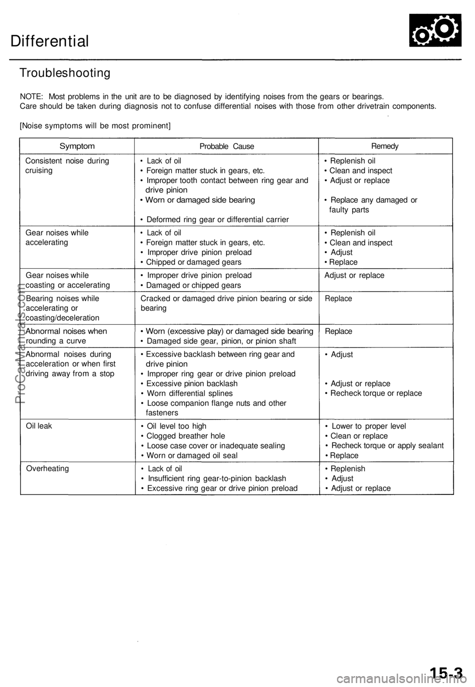
Differential
Troubleshootin g
NOTE: Mos t problem s i n th e uni t ar e t o b e diagnose d b y identifyin g noise s fro m th e gear s o r bearings .
Car e shoul d b e take n durin g diagnosi s no t t o confus e differentia l noise s wit h thos e fro m othe r drivetrai n components .
[Nois e symptom s wil l b e mos t prominent ]
Symptom
Consisten t nois e during
cruisin g
Gea r noise s whil e
acceleratin g
Gea r noise s whil e
coastin g o r acceleratin g
Bearin g noise s whil e
acceleratin g o r
coasting/deceleratio n
Abnormal noise s whe n
roundin g a curv e
Abnorma l noise s durin g
acceleratio n o r whe n firs t
drivin g awa y fro m a sto p
Oi l lea k
Overheatin g Probabl
e Caus e
• Lac k o f oi l
• Foreig n matte r stuc k in gears , etc .
• Imprope r toot h contac t betwee n rin g gea r an d
driv e pinio n
• Wor n o r damage d sid e bearin g
• Deforme d rin g gea r o r differentia l carrie r
• Lac k o f oi l
• Foreig n matte r stuc k in gears , etc .
• Imprope r driv e pinio n preloa d
• Chippe d o r damage d gear s
• Imprope r driv e pinio n preloa d
• Damage d o r chippe d gear s
Cracke d o r damage d driv e pinio n bearin g o r sid e
bearin g
• Wor n (excessiv e play ) o r damage d sid e bearin g
• Damage d sid e gear , pinion , o r pinio n shaf t
• Excessiv e backlas h betwee n rin g gea r an d
driv e pinio n
• Imprope r rin g gea r o r driv e pinio n preloa d
• Excessiv e pinio n backlas h
• Wor n differentia l spline s
• Loos e companio n flang e nut s an d othe r
fastener s
• Oi l leve l to o hig h
• Clogge d breathe r hol e
• Loos e cas e cove r o r inadequat e sealin g
• Wor n o r damage d oi l sea l
• Lac k o f oi l
• Insufficien t rin g gear-to-pinio n backlas h
• Excessiv e rin g gea r o r driv e pinio n preloa d Remed
y
• Replenis h oi l
• Clea n an d inspec t
• Adjus t o r replac e
• Replac e an y damage d o r
fault y part s
• Replenis h oi l
• Clea n an d inspec t
• Adjus t
• Replac e
Adjus t o r replac e
Replac e
Replace
• Adjus t
• Adjus t o r replac e
• Rechec k torqu e o r replac e
• Lowe r t o prope r leve l
• Clea n o r replac e
• Rechec k torqu e o r appl y sealan t
• Replac e
• Replenis h
• Adjus t
• Adjus t o r replac e
ProCarManuals.com
Page 915 of 1954

Maintenance
Differential Oil
NOTE: Check the differential oil with engine OFF, and
the vehicle on level ground.
1. Remove the oil filler plug, then check the level and
condition of the oil.
WASHER
Replace.
Proper Lever
OIL FILLER PLUG
44 N-m (4.5 kgf-m, 33 Ibf-ft)
WASHER Replace.
2. The oil level must be up to the fill hole. If it is below
the hole, add oil until it runs out, then reinstall the
oil filler plug with a new washer.
3. If the differential oil is dirty, remove the drain plug,
and drain the oil.
DRAIN PLUG
39 N-m (4.0 kgf-m, 29 Ibf-ft)
WASHER Replace.
OIL FILLER PLUG
44 N-m (4.5 kgf-m, 33 Ibf-ft)
4. Reinstall the drain plug with a new washer, and refill
the differential with the recommended oil to the
proper level.
NOTE:
The drain plug washer should be replaced at every
oil change.
Clean the drain plug before reinstalling.
5. Reinstall the oil filler plug with a new washer.
Oil Capacity
1.05 (1.11 US qt, 0.92 Imp qt) at oil change
1.10 (1.16 US qt, 0.97 Imp qt) at overhaul
Recommended oil:
Hypoid gear oil
API Classification GL4 or GL5
viscosity:
SAE 90 above 0°F (-18°C)
SAE 80 W - 90 below 0°F (-18°C)ProCarManuals.com
Page 916 of 1954

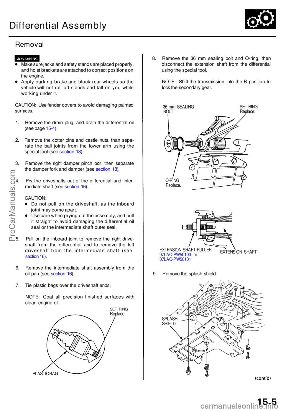
Differential Assembly
Removal
Make sur e jack s an d safet y stand s ar e place d properly ,
an d hois t bracket s ar e attache d to correc t position s o n
th e engine .
Appl y parkin g brak e an d bloc k rea r wheel s s o th e
vehicl e wil l no t rol l of f stand s an d fal l o n yo u whil e
workin g unde r it .
CAUTION : Us e fende r cover s to avoi d damagin g painte d
surfaces .
1. Remov e th e drai n plug , an d drai n th e differentia l oi l
(se e pag e 15-4 ).
2 . Remov e th e cotte r pin s an d castl e nuts , tha n sepa -
rat e th e bal l joint s fro m th e lowe r ar m usin g th e
specia l too l (se e sectio n 18 ).
3 . Remov e th e righ t dampe r pinc h bolt , the n separat e
th e dampe r for k an d dampe r (se e sectio n 18 ).
4 . Pr y th e driveshaft s ou t o f th e differentia l an d inter -
mediat e shaf t (se e sectio n 16 ).
CAUTION :
D o no t pul l o n th e driveshaft , a s th e inboar d
join t ma y com e apart .
Us e car e whe n pryin g ou t th e assembly , an d pul l
i t straigh t t o avoi d damagin g th e differentia l oi l
sea l o r th e intermediat e shaf t oute r seal .
5 . Pul l o n th e inboar d join t t o remov e th e righ t drive -
shaf t fro m th e differentia l an d t o remov e th e lef t
driveshaft from the intermediate shaft (see
section 16 ).
6 . Remov e th e intermediat e shaf t assembl y fro m th e
oi l pa n (se e sectio n 16 ).
7 . Ti e plasti c bag s ove r th e driveshaf t ends .
NOTE : Coa t al l precisio n finishe d surface s wit h
clea n engin e oil .
SE T RIN GReplace .
PLASTIC BA G
8. Remov e th e 3 6 m m sealin g bol t an d O-ring , the n
disconnec t th e extensio n shaf t fro m th e differentia l
usin g th e specia l tool .
NOTE : Shif t th e transmissio n int o th e B positio n t o
loc k th e secondar y gear .
36 m m SEALIN GBOLTSET RIN GReplace .
O-RINGReplace .
EXTENSIO N SHAF T PULLE R
07LAC-PW5010 0 o r
07LAC-PW5010 1 EXTENSIO
N SHAF T
9. Remov e th e splas h shield .
SPLAS HSHIELD
ProCarManuals.com
Page 917 of 1954
Differential Assembl y
Removal (cont'd )
10. Remov e th e lowe r plate , the n reinstal l th e steerin g
gearbo x mountin g bolts .
STEERIN G GEARBO XMOUNTING BOLT S
5 9 N- m (6. 0 kgf-m ,
4. 3 Ibf-ft )
LOWE R PLAT E
11. Disconnec t th e vehicl e spee d senso r (VSS ) connec -
tor , the n remov e th e VSS/powe r steerin g spee d
sensor .
NOTE : D o no t disconnec t th e hoses .
VSS CONNECTO R
VSS/POWE R STEERIN G
SPEE D SENSO R
12. Remov e th e ai r cleane r housin g assembly .
AIR CLEANE RHOUSING ASSEMBL Y
13. Remov e th e powe r steerin g pump .
NOTE : D o no t disconnec t th e hoses .
POWER STEERIN G
PUM P
ProCarManuals.com
Page 919 of 1954
Differential Assembl y
Removal (cont'd )
19. Remov e th e mountin g bolt s an d 2 6 m m shim , the n
remov e th e differential assembly.
O-RINGReplace .
DIFFERENTIA L
ASSEMBL Y
26 m m SHI M
ProCarManuals.com