Page 932 of 1954

Differential Assembl y
Reassembl y (cont'd )
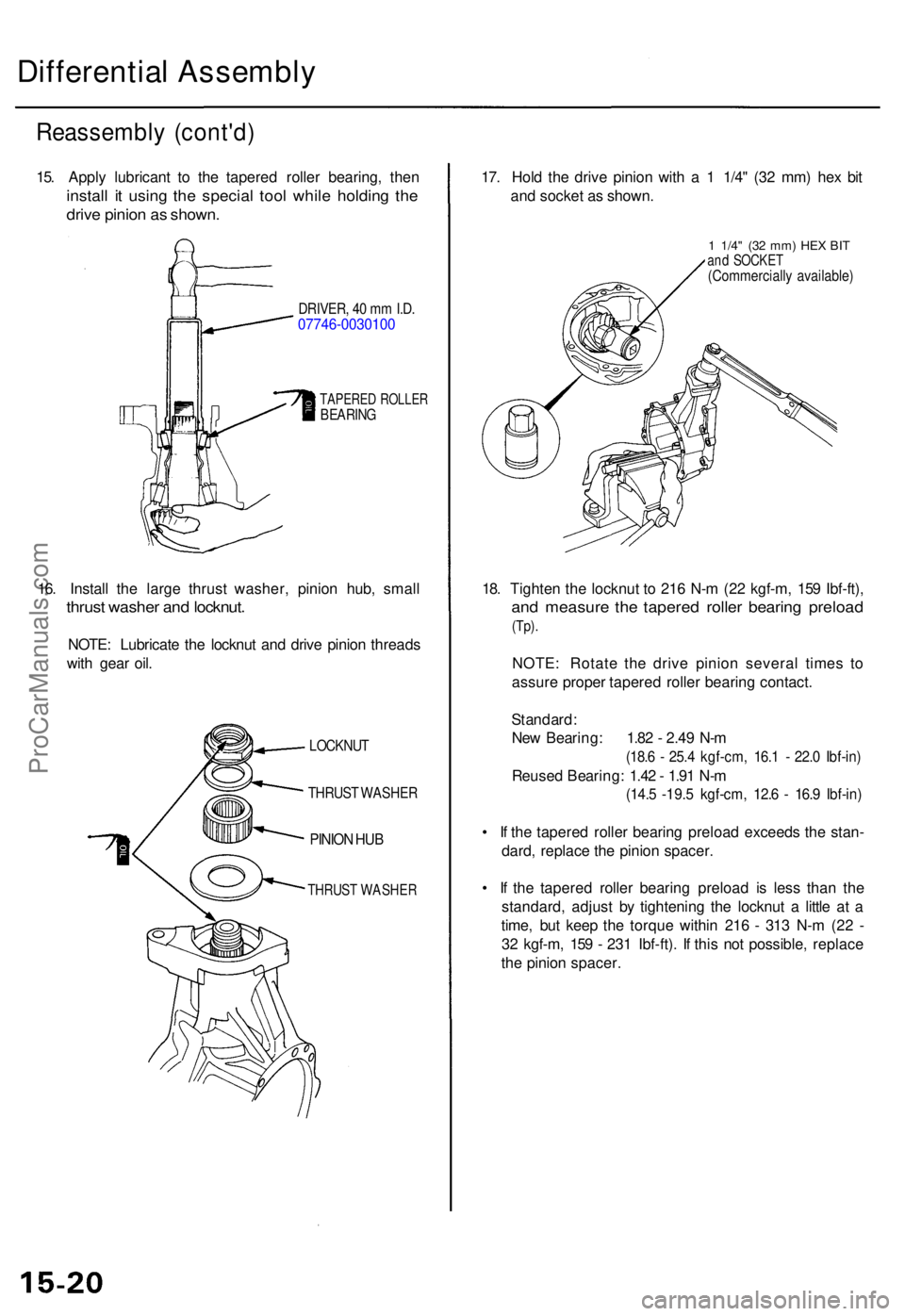
15. Appl y lubrican t t o th e tapere d rolle r bearing , the n
instal l i t usin g th e specia l too l whil e holdin g th e
driv e pinio n a s shown .
DRIVER , 4 0 m m I.D .07746-003010 0
TAPERED ROLLE RBEARIN G
16. Instal l th e larg e thrus t washer , pinio n hub , smal l
thrust washe r an d locknut .
NOTE: Lubricat e th e locknu t an d driv e pinio n thread s
wit h gea r oil .
LOCKNU T
THRUS T WASHE R
PINION HU B
THRUS T WASHE R
17. Hol d th e driv e pinio n wit h a 1 1/4 " (3 2 mm ) he x bi t
an d socke t a s shown .
1 1/4" (32 mm ) HE X BI Tand SOCKE T(Commerciall y available )
18. Tighte n th e locknu t t o 21 6 N- m (2 2 kgf-m , 15 9 Ibf-ft) ,
and measur e th e tapere d rolle r bearin g preloa d
(Tp).
NOTE : Rotat e th e driv e pinio n severa l time s t o
assur e prope r tapere d rolle r bearin g contact .
Standard :
Ne w Bearing : 1.8 2 - 2.4 9 N- m
(18. 6 - 25. 4 kgf-cm , 16. 1 - 22. 0 Ibf-in )
Reuse d Bearing : 1.4 2 - 1.9 1 N- m
(14. 5 -19. 5 kgf-cm , 12. 6 - 16. 9 Ibf-in )
• I f th e tapere d rolle r bearin g preloa d exceed s th e stan -
dard , replac e th e pinio n spacer .
• I f th e tapere d rolle r bearin g preloa d i s les s tha n th e
standard , adjus t b y tightenin g th e locknu t a littl e a t a
time , bu t kee p th e torqu e withi n 21 6 - 31 3 N- m (2 2 -
3 2 kgf-m , 15 9 - 23 1 Ibf-ft) . I f thi s no t possible , replac e
th e pinio n spacer .
ProCarManuals.com
Page 934 of 1954

Differential Assembl y
Reassembl y (cont'd )
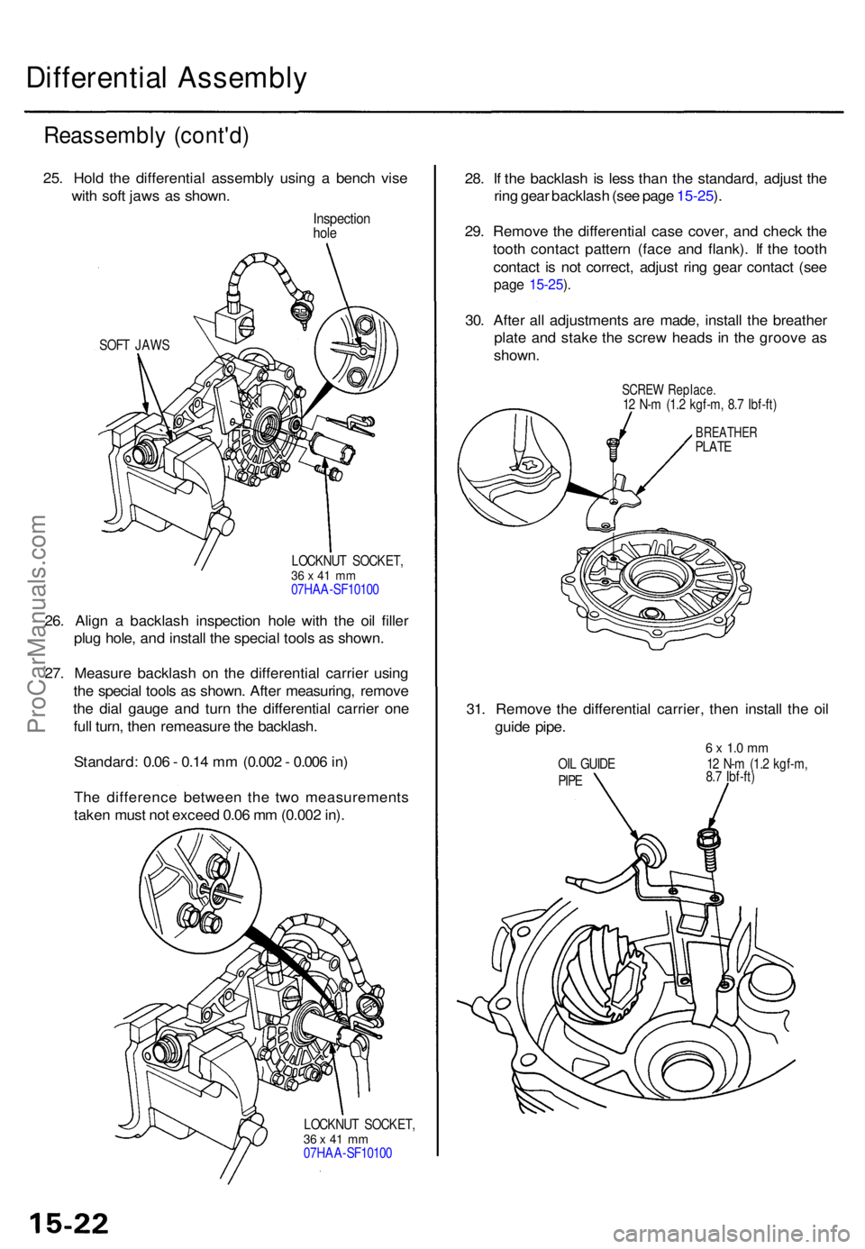
25. Hol d th e differentia l assembl y usin g a benc h vise
wit h sof t jaw s a s shown .
Inspectio nhole
SOF T JAW S
LOCKNUT SOCKET ,
36 x 41 m m07HA A-SF1010 0
26. Alig n a backlas h inspectio n hol e wit h th e oi l fille r
plu g hole , an d instal l th e specia l tool s a s shown .
27 . Measur e backlas h o n th e differentia l carrie r usin g
th e specia l tool s a s shown . Afte r measuring , remov e
th e dia l gaug e an d tur n th e differentia l carrie r on e
ful l turn , the n remeasur e th e backlash .
Standard : 0.0 6 - 0.1 4 m m (0.00 2 - 0.00 6 in )
Th e differenc e betwee n th e tw o measurement s
take n mus t no t excee d 0.0 6 m m (0.00 2 in) .
LOCKNU T SOCKET ,36 x 41 m m07HA A-SF1010 0
28. I f th e backlas h i s les s tha n th e standard , adjus t th e
rin g gea r backlas h (se e pag e 15-25 ).
29 . Remov e th e differentia l cas e cover , an d chec k th e
toot h contac t patter n (fac e an d flank) . I f th e toot h
contac t i s no t correct , adjus t rin g gea r contac t (se e
page 15-25 ).
30 . Afte r al l adjustment s ar e made , instal l th e breathe r
plat e an d stak e th e scre w head s i n th e groov e a s
shown .
SCREW Replace .12 N- m (1. 2 kgf-m , 8. 7 Ibf-ft )
BREATHE RPLATE
31. Remov e th e differentia l carrier , the n instal l th e oi l
guid e pipe .
6 x 1. 0 m m
OIL GUID E 1 2 N- m (1. 2 kgf-m ,
PIP E 8.
7 Ibf-ft )
ProCarManuals.com
Page 938 of 1954

Differential Assembl y
Installation
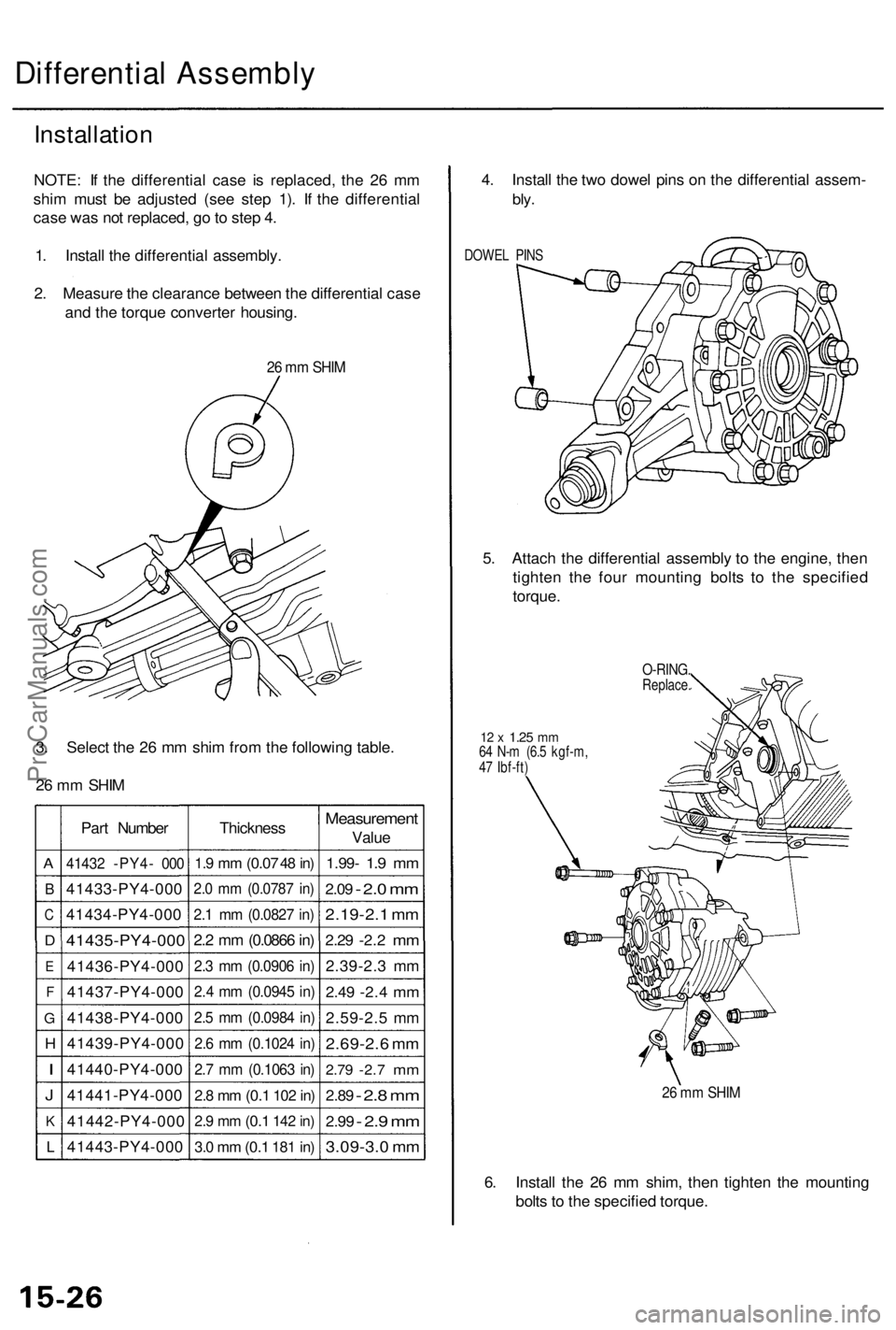
NOTE: I f th e differentia l cas e i s replaced , th e 2 6 m m
shi m mus t b e adjuste d (se e ste p 1) . I f th e differentia l
cas e wa s no t replaced , g o to ste p 4 .
1 . Instal l th e differentia l assembly .
2 . Measur e th e clearanc e betwee n th e differentia l cas e
an d th e torqu e converte r housing .
26 m m SHI M
3. Selec t th e 2 6 m m shi m fro m th e followin g table .
2 6 m m SHI M
A
B
C
D
E
F
G
H
I
J
K
L
Part Numbe r
41432 -PY4 - 00 0
41433-PY4-00 0
41434-PY4-00 0
41435-PY4-000
41436-PY4-00 0
41437-PY4-00 0
41438-PY4-00 0
41439-PY4-00 0
41440-PY4-00 0
41441-PY4-00 0
41442-PY4-00 0
41443-PY4-00 0Thicknes
s
1.9 m m (0.0 7 48 in )
2.0 m m (0.078 7 in )
2.1 m m (0.082 7 in )
2.2 m m (0.086 6 in )
2.3 m m (0.090 6 in )
2.4 m m (0.094 5 in )
2.5 m m (0.098 4 in )
2.6 m m (0.102 4 in )
2.7 m m (0.106 3 in )
2.8 m m (0. 1 102 in )
2.9 m m (0. 1 142 in )
3.0 m m (0. 1 181 in )
Measuremen t
Value
1.99- 1.9 m m
2.0 9 - 2.0 m m
2.19-2. 1 m m
2.2 9 -2. 2 mm
2.39-2. 3 m m
2.4 9 -2. 4 mm
2.59-2. 5 m m
2.69-2. 6 m m
2.7 9 -2. 7 mm
2.89 - 2.8 m m
2.9 9 - 2.9 m m
3.09-3. 0 m m
4. Instal l th e tw o dowe l pin s o n th e differentia l assem -
bly.
DOWE L PIN S
5. Attac h th e differentia l assembl y t o th e engine , the n
tighte n th e fou r mountin g bolt s t o th e specifie d
torque .
O-RING .Replace .
12 x 1.2 5 mm64 N- m (6. 5 kgf-m ,
4 7 Ibf-ft )
26 m m SHI M
6. Instal l th e 2 6 m m shim , the n tighte n th e mountin g
bolt s t o th e specifie d torque .
ProCarManuals.com
Page 940 of 1954

Differential Assembl y
Installation (cont'd )
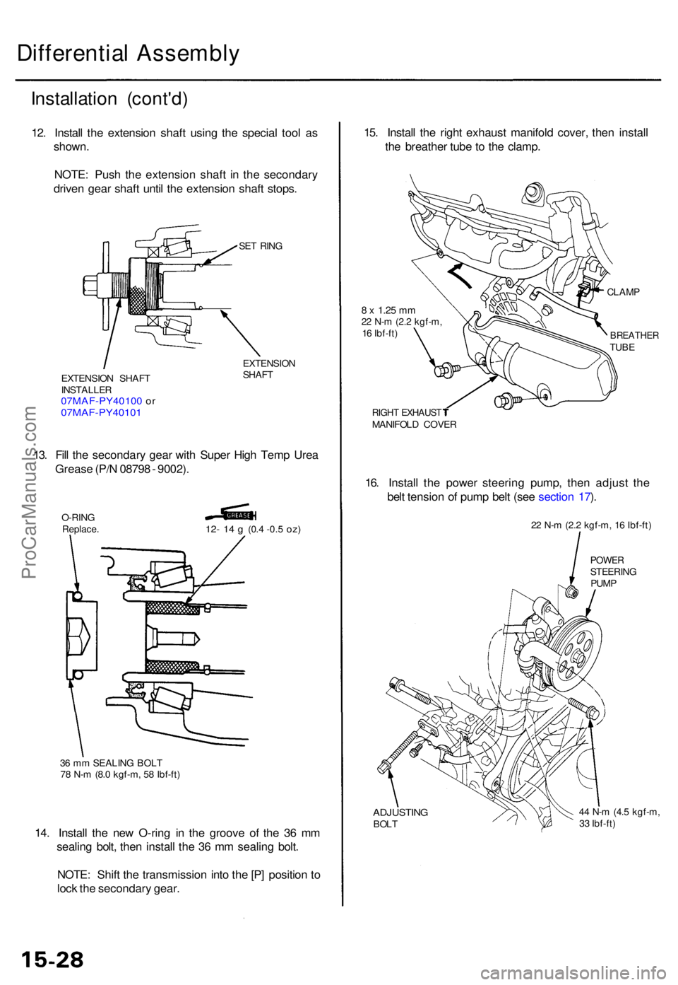
12. Instal l th e extensio n shaf t usin g th e specia l too l a s
shown .
NOTE : Pus h th e extensio n shaf t i n th e secondar y
drive n gea r shaf t unti l th e extensio n shaf t stops .
EXTENSIO N
SHAF T
EXTENSIO N SHAF T
INSTALLE R
07MAF-PY40100 or07MAF-PY4010 1
13. Fil l th e secondar y gea r wit h Supe r Hig h Tem p Ure a
Greas e (P/ N 0879 8 - 9002) .
O-RIN GReplace .12- 1 4 g (0. 4 -0. 5 oz)
36 m m SEALIN G BOL T
7 8 N- m (8. 0 kgf-m , 5 8 Ibf-ft )
14. Instal l th e ne w O-rin g i n th e groov e o f th e 3 6 m m
sealin g bolt , the n instal l th e 3 6 m m sealin g bolt .
NOTE : Shif t th e transmissio n int o th e [P ] positio n t o
loc k th e secondar y gear . 15
. Instal l th e righ t exhaus t manifol d cover , the n instal l
th e breathe r tub e to th e clamp .
8 x 1.2 5 mm22 N- m (2. 2 kgf-m ,
1 6 Ibf-ft ) CLAM
P
BREATHE RTUBE
RIGH T EXHAUS TMANIFOL D COVE R
16. Instal l th e powe r steerin g pump , the n adjus t th e
bel t tensio n o f pum p bel t (se e sectio n 17 ).
2 2 N- m (2. 2 kgf-m , 1 6 Ibf-ft )
POWE RSTEERIN G
PUM P
ADJUSTIN GBOLT44 N- m (4. 5 kgf-m ,
3 3 Ibf-ft )
SE
T RIN G
ProCarManuals.com
Page 941 of 1954

17. Instal l th e ai r cleane r housin g assembly .
6 x 1. 0 m m9.8 N- m (1. 0 kgf-m , 7. 2 Ibf-ft )
AIR CLEANE RHOUSING ASSEMBL Y
18. Instal l th e vehicl e spee d senso r (VSS)/powe r steer -
in g spee d sensor , the n connec t th e VS S connector .
6 x 1. 0 m m12 N- m (1. 2 kgf-m , 8. 7 Ibf-ft )
VSS CONNECTO R
O-RIN G
Replace . VSS/POWE R STEERIN G
SPEE D SENSO R
19. Remov e th e steerin g gearbo x mountin g bolts , the n
instal l th e lowe r plat e an d th e steerin g gearbo x
mounting bolts .
STEERIN G GEARBO XMOUNTING BOLT S59 N- m (6. 0 kgf-m ,
4 3 Ibf-ft )
10 x 1.2 5 mm38 N- m (3. 9 kgf-m ,
2 8 Ibf-ft )
20. Instal l th e driveshaft s an d th e intermediat e shaf t
(se e sectio n 16 ).
CAUTION : Whil e installin g th e driveshaf t an d th e
intermediat e shaf t i n th e differential , b e sur e no t t o
allo w dus t an d othe r foreig n particle s t o ente r int o
th e differential .
21 . Instal l th e dampe r fork , the n instal l th e righ t an d lef t
bal l joint s t o th e eac h lowe r ar m wit h th e castl e nut s
an d ne w cotte r pin s (se e sectio n 18 ).
LOWE RPLATE
ProCarManuals.com
Page 942 of 1954
Differential Assembl y
Installatio n (cont'd )
22. Instal l th e splas h shield .
SPLAS H SHIEL D
6 x 1. 0 m m9.8 N- m (1. 0 kgf-m , 7. 2 Ibf-ft )
23. Refil l th e differentia l wit h th e recommende d oi l (se e
pag e 15-4 ).
ProCarManuals.com
Page 960 of 1954
Intermediate Shaf t
Remova l
1. Drai n th e differentia l oi l (se e sectio n 15 ).
2 . Remov e th e lef t driveshaf t (se e pag e 16-3 ).
3 . Remov e th e thre e flang e bolts .
FLANG E BOL T8 x 1.2 5 mm
4. Remov e th e intermediat e shaf t fro m th e differential .
INTERMEDIAT E SHAFT
ProCarManuals.com
Page:
< prev 1-8 9-16 17-24