Page 27 of 1954

Mirrors
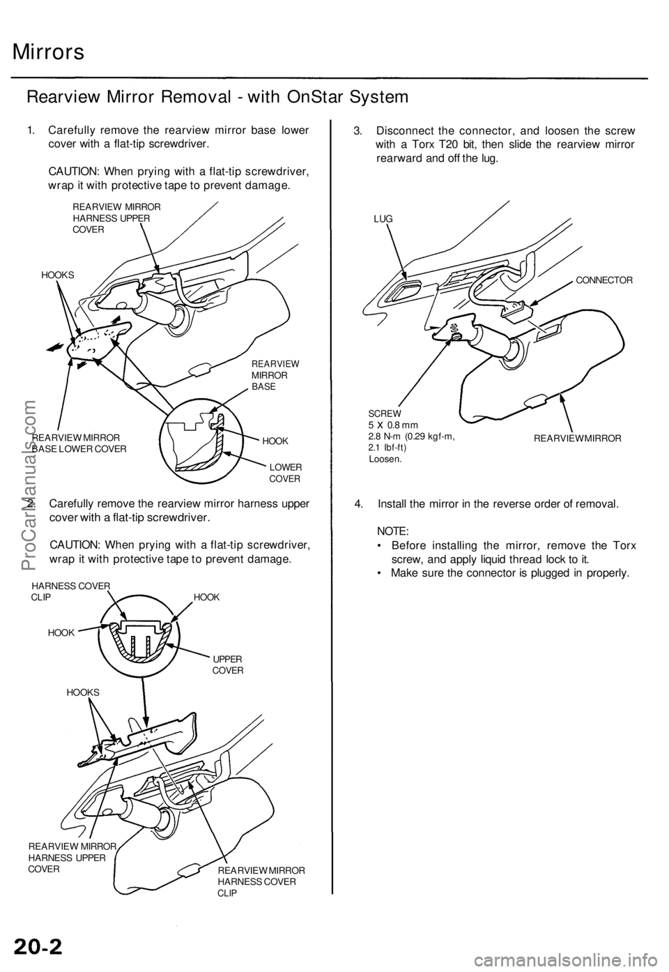
Rearvie w Mirro r Remova l - wit h OnSta r Syste m
1. Carefull y remov e th e rearvie w mirro r bas e lowe r
cove r wit h a flat-ti p screwdriver .
CAUTION : Whe n pryin g wit h a flat-ti p screwdriver ,
wra p it wit h protectiv e tap e t o preven t damage .
REARVIE W MIRRO RHARNES S UPPE R
COVE R
HOOK S
REARVIE W MIRRO R
BAS E LOWE R COVE RHOOK
LOWE RCOVER
2. Carefull y remov e th e rearvie w mirro r harnes s uppe r
cover wit h a flat-ti p screwdriver .
CAUTION: Whe n pryin g wit h a flat-ti p screwdriver ,
wra p it wit h protectiv e tap e t o preven t damage .
HARNES S COVE RCLIP
HOO K
HOO K
UPPE RCOVE R
REARVIE W MIRRO R
HARNES S UPPE R
COVERREARVIE W MIRRO R
HARNES S COVE R
CLIP
3. Disconnec t th e connector , an d loose n th e scre w
wit h a Tor x T2 0 bit , the n slid e th e rearvie w mirro r
rearwar d an d of f th e lug .
LUG
CONNECTO R
SCREW5 x 0.8 m m2.8 N- m (0.2 9 kgf-m ,2.1 Ibf-ft )Loosen . REARVIE
W MIRRO R
4. Instal l th e mirro r i n th e revers e orde r o f removal .
NOTE:
• Befor e installin g th e mirror , remov e th e Tor x
screw , an d appl y liqui d threa d loc k t o it .
• Mak e sur e th e connecto r i s plugge d i n properly .
HOOKS
REARVIEWMIRRO RBASE
ProCarManuals.com
Page 41 of 1954

Test/Replacement ('0 2-04 Mode l USA )
NOTE : Befor e testing , chec k th e No . 1 3 (7. 5 A ) fuse . No .
7 , 10 , 11 , 13 , 1 4 an d 1 5 terminal s ar e OnSta r switche s
microphon e power , groun d an d signa l lines .
1 . Disconnec t th e 16 P connecto r fro m th e mirror . 2
. Chec k fo r voltag e betwee n th e No . 1 2 termina l an d
bod y groun d wit h th e ignitio n switc h O N (II) .
• I f ther e is batter y voltage , g o to ste p 3 .
• I f ther e is n o voltage , chec k for :
— an ope n in th e wire , o r
— poo r groun d (G401 , G402) .
3 . Chec k fo r voltag e betwee n th e No . 1 6 termina l an d
bod y groun d wit h th e ignitio n switc h O N (II ) an d
A/T gea r positio n in
• I f ther e i s batter y voltage , replac e th e mirro r b y
removin g tor x screw .
• I f ther e is n o voltage , chec k for :
— an ope n in th e wire , o r
— fault y revers e relay , o r
— fault y transmissio n rang e switch , o r
— fault y diode .
Wire sid e o ffemal e terminal s
ProCarManuals.com
Page 1081 of 1954
Component Locations
ABS CONTROL UNIT
MODULATOR UNIT
SERVICE CHECK CONNECTOR (2P)
ABS INSPECTION CONNECTOR (6P)
RIGHT-REAR WHEEL SENSOR
RIGHT-FRONT WHEEL
SENSOR CONNECTOR
RIGHT-FRONT
WHEEL SENSOR
LEFT-REAR WHEEL
SENSOR CONNECTOR
LEFT-REAR
WHEEL SENSOR
RIGHT-REAR WHEEL
SENSOR CONNECTOR
UNDER-HOOD
RELAY BOX B
UNDER-HOOD
FUSE/RELAY BOX
UNDER-DASH FUSE/RELAY BOX
LEFT-FRONT WHEEL SENSOR
LEFT-FRONT WHEEL
SENSOR CONNECTOR
GAUGE ASSEMBLY:
ABS INDICATOR LIGHT
UNDER-DASH FUSE/RELAY BOX:
METER
(7.5 A) FUSE
ABS B2
(15 A) FUSE
ABS B1
(20 A) FUSE
METER
(15 A) FUSE
BATTERY
(120 A) FUSE
ABS MOTOR (40 A) FUSE
IG SW (50 A) FUSE
UNDER-HOOD RELAY BOX C:
REAR FAIL-SAFE RELAY
METER RELAY
FRONT FAIL-SAFE RELAY
ABS
UNIT
(7.5 A) FUSE
STOP/HORN
(ISA) FUSE
ABS PUMP
MOTOR RELAY
UNDER-HOOD FUSE/RELAY BOX:
ECU
(20 A) FUSE
R/C MIRROR
(7.5 A) FUSEProCarManuals.com
Page 1151 of 1954
Component Locations
SERVICE CHECK CONNECTOR (2P)
RIGHT-REAR WHEEL SENSOR
ABS CONTROL UNIT
MODULATOR UNIT
LEFT-REAR
WHEEL SENSOR
RIGHT-FRONT
WHEEL SENSOR
UNDER-HOOD RELAY BOX C
UNDER-DASH FUSE/RELAY BOX
LEFT-FRONT WHEEL SENSOR
GAUGE ASSEMBLY
UNDER-HOOD FUSE/RELAY BOX
ABS INDICATOR
UNDER-DASH FUSE/RELAY BOX
R/C MIRROR
(7.5 A) FUSE
METER
(7.5 A) FUSE
STOP/HORN
(15 A) FUSE
ABS
UNIT
(7.5 A) FUSE
ABS
(20 A) FUSE
ABS PUMP
MOTOR RELAY
METER
(15 A) FUSE
BATTERY
(120 A) FUSE
ABS MOTOR
(40 A) FUSE
IG SW (50 A) FUSE
UNDER-HOOD RELAY BOX C
GAUGE RELAY
FAIL-SAFE RELAY
UNDER-HOOD FUSE/RELAY BOXProCarManuals.com
Page 1234 of 1954
Component Locations
SERVICE CHECK CONNECTOR (2P)
RIGHT-REAR WHEEL SENSOR
VSA CONVERTER UNIT
VSA MODULATOR
CONTROL UNIT
TCS CONTROL
VALVE SENSOR
RIGHT-FRONT
WHEEL SENSOR
PRECHARGE
PUMP MOTOR
STEERING
ANGLE SENSOR
YAW RATE/LATERAL
ACCELERATION SENSOR
TCS CONTROL VALVE
ACTUATOR
UNDER-HOOD
RELAY BOX C
UNDER-HOOD
FUSE/RELAY BOX
VSA OFF SWITCH
UNDER-DASH FUSE/RELAY BOX
LEFT-FRONT WHEEL SENSOR
LEFT-REAR
WHEEL SENSOR
GAUGE ASSEMBLY
ABS INDICATOR
VSA SYSTEM INDICATOR
UNDER-HOOD FUSE/RELAY BOX
STOP/HORN
(20 A) FUSE
BRAKE SYSTEM INDICATOR
VSA ACTIVATION INDICATOR
UNDER-DASH FUSE/RELAY BOX
TCS
(15 A) FUSE
VSA
(20 A) FUSE
METER
(15 A) FUSE
ECU
(20 A) FUSE
METER
(7.5 A) FUSE
BATTERY
(120 A) FUSE
VSA MOTOR (40 A) FUSE
IG SW (50 A) FUSE
UNDER-HOOD RELAY BOX C
FAIL-SAFE RELAY
GAUGE RELAY
PCM
R/C MIRROR
(7.5 A) FUSEProCarManuals.com
Page 1311 of 1954
Doors
Front Doo r Inde xSASH TRI M
Removal , pag e
20-8OUTE RWEATHERSTRI PMIRRORRemoval , pag e20-18INNE R SAS HTRIMRemoval , pag e20-8
INNE RMOLDIN G
OUTERMOLDIN G
FRONTCORNE RTRIM
HING E
PLASTI C
COVER
MEMOR Y
CONTRO L
UNITTWEETE R(for som e models )
COURTES Y
LIGH T
SPEAKE RCOVER
CAP
POWE R WINDO W
SWITC HPOWERWINDO WSWITCHDOOR POCKE T
LOWE
R PA D
ARMRES
T
PAD
SWITC HTRIM
POWE R SEA T
MEMOR Y SWITC H
(driver's )
POWER MIRRO R
SWITCH(driver's )TRUN
K LI D
OPENE RSWITCH
(driver's ) Passenger's
:
SWITC HPANEL
SWITC HPANEL
DOORPOCKE T
DOOR PANE L
Removal , pag e 20- 4
DOO
R
PROTECTO R
TWEETERGRILLE
TWEETE R(for som e models )
STO
P
LOC
K KNO B
COVE R
DYNAMI CDAMPER
SWITCHBRACKE TSPEAKERSPACER
ADAPTE R
DETENTROD
SECURIT Y
INDICATO R
(driver's )
INNE
R
WEATHERSTRI P
DOORAdjustment ,page 20-1 7
ProCarManuals.com
Page 1329 of 1954

Doors Mirrors
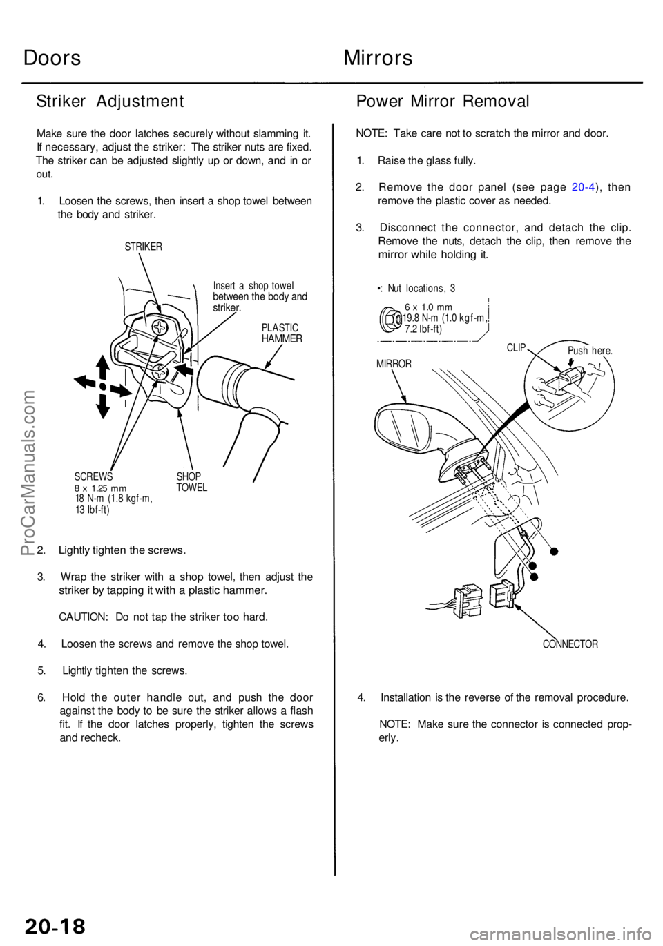
Striker Adjustmen t
Make sur e th e doo r latche s securel y withou t slammin g it .
I f necessary , adjus t th e striker : Th e strike r nut s ar e fixed .
Th e strike r ca n b e adjuste d slightl y u p o r down , an d i n o r
out .
1. Loose n th e screws , the n inser t a sho p towe l betwee n
th e bod y an d striker .
STRIKE R
PLASTICHAMME R
2. Lightl y tighte n th e screws .
3. Wra p th e strike r wit h a sho p towel , the n adjus t th e
strike r b y tappin g it wit h a plasti c hammer .
CAUTION : D o no t ta p th e strike r to o hard .
4 . Loose n th e screw s an d remov e th e sho p towel .
5 . Lightl y tighte n th e screws .
6 . Hol d th e oute r handl e out , an d pus h th e doo r
agains t th e bod y t o b e sur e th e strike r allow s a flas h
fit . I f th e doo r latche s properly , tighte n th e screw s
an d recheck .
Power Mirro r Remova l
NOTE: Tak e car e no t t o scratc h th e mirro r an d door .
1 . Rais e th e glas s fully .
2 . Remov e th e doo r pane l (se e pag e 20-4 ), the n
remov e th e plasti c cove r a s needed .
3 . Disconnec t th e connector , an d detac h th e clip .
Remov e th e nuts , detac h th e clip , the n remov e th e
mirro r whil e holdin g it .
•: Nu t locations , 3
6 x 1. 0 m m19. 8 N- m (1. 0 kgf-m ,
7. 2 Ibf-ft )
CONNECTOR
4. Installatio n i s th e revers e o f th e remova l procedure .
NOTE : Mak e sur e th e connecto r i s connecte d prop -
erly .
Inser t a sho p towe lbetwee n th e bod y an dstriker .
MIRRO R
CLIPPus h here .
SCREW S
8 x 1.2 5 mm18 N- m (1. 8 kgf-m ,
1 3 Ibf-ft ) SHO
P
TOWE L
ProCarManuals.com
Page 1330 of 1954
Mirror Holder Removal
NOTE: Take care not to scratch the mirror housing.
1. Pry the mirror holder out from the bottom until you
can see the actuator, then detach the hooks using a
flat tip screwdriver.
CAUTION: When prying with a flat-tip screwdriver,
wrap it with a shop towel to prevent damage.
ADHESIVE TAPE
HOOKS
MIRROR
HOUSING
SHOP
TOWEL
MIRROR
HOLDER
2. Detach the hooks, disconnect the defogger connec-
tor (if so equipped), then remove the mirror holder
from the actuator.
ACTUATOR
HOOK
DEFOGGER
CONNECTOR
MIRROR HOLDER
3. Installation is the reverse of the removal procedure.ProCarManuals.com