1996 ACURA RL KA9 mirror
[x] Cancel search: mirrorPage 1623 of 1954
Driving Positio n Memor y Syste m (DPMS )
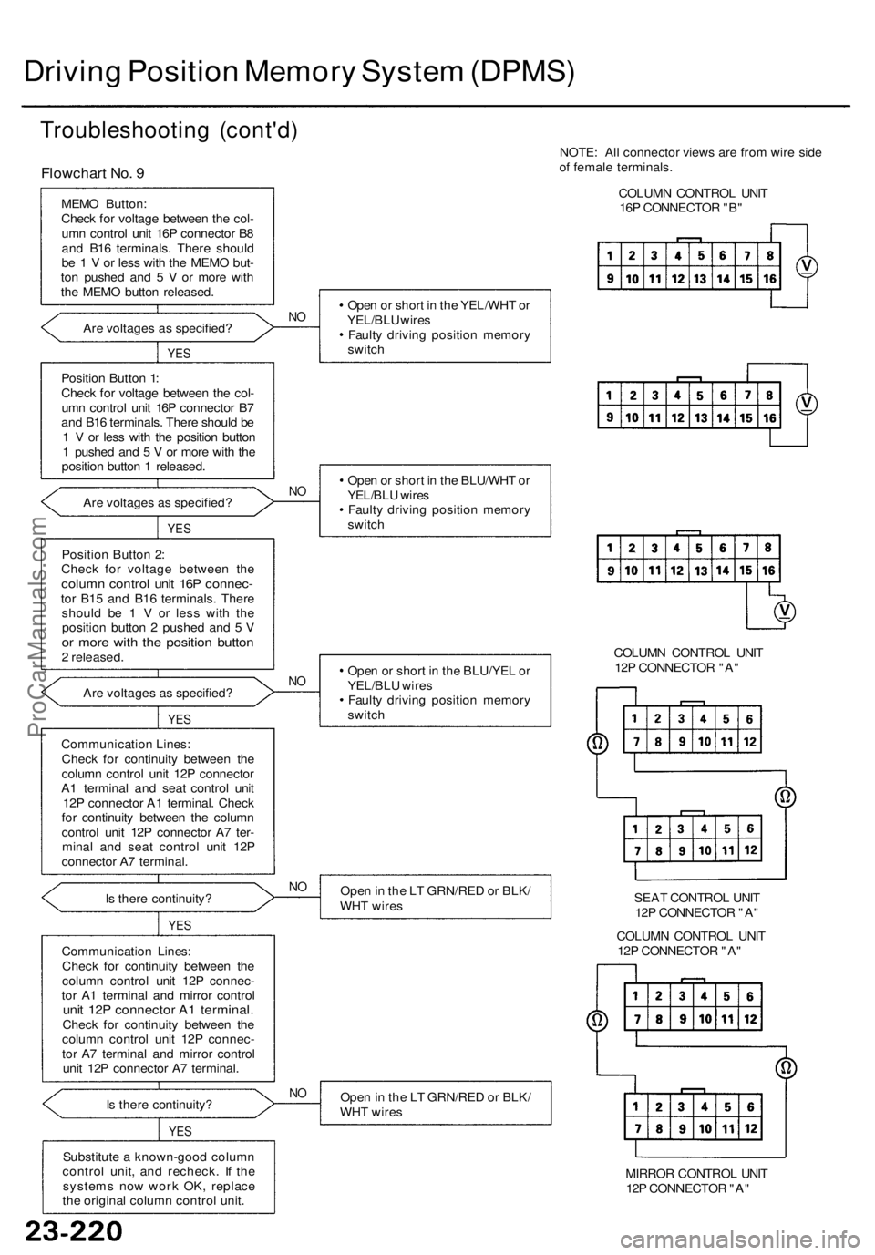
Troubleshootin g (cont'd )
Flowchar t No . 9
MEM O Button :
Chec k fo r voltag e betwee n th e col -
um n contro l uni t 16 P connecto r B 8
an d B1 6 terminals . Ther e shoul d
b e 1 V or les s wit h th e MEM O but -
to n pushe d an d 5 V or mor e wit h
th e MEM O butto n released .
Ar e voltage s a s specified ?
YES
Positio n Butto n 1 :
Chec k fo r voltag e betwee n th e col -
um n contro l uni t 16 P connecto r B 7
an d B1 6 terminals . Ther e shoul d b e
1 V or les s wit h th e positio n butto n
1 pushe d an d 5 V or mor e wit h th e
positio n butto n 1 released .
Ar e voltage s a s specified ?
YES
Positio n Butto n 2 :
Chec k fo r voltag e betwee n th e
colum n contro l uni t 16 P connec -tor B1 5 an d B1 6 terminals . Ther e
shoul d b e 1 V or les s wit h th e
positio n butto n 2 pushe d an d 5 V
or mor e wit h th e positio n butto n2 released .
Ar e voltage s a s specified ?
YES
Communicatio n Lines :
Chec k fo r continuit y betwee n th e
colum n contro l uni t 12 P connecto r
A 1 termina l an d sea t contro l uni t
12 P connecto r A 1 terminal . Chec k
fo r continuit y betwee n th e colum n
contro l uni t 12 P connecto r A 7 ter -
mina l an d sea t contro l uni t 12 P
connecto r A 7 terminal .
I s ther e continuity ?
YES
Communicatio n Lines :
Chec k fo r continuit y betwee n th e
colum n contro l uni t 12 P connec -
to r A 1 termina l an d mirro r contro l
unit 12 P connecto r A 1 terminal .Check fo r continuit y betwee n th e
colum n contro l uni t 12 P connec -
to r A 7 termina l an d mirro r contro l
uni t 12 P connecto r A 7 terminal .
I s ther e continuity ?
YES
Substitut e a known-goo d colum n
contro l unit , an d recheck . I f th e
system s no w wor k OK , replac e
th e origina l colum n contro l unit . NOTE
: Al l connecto r view s ar e fro m wir e sid e
o f femal e terminals .
COLUM N CONTRO L UNI T
16 P CONNECTO R "B "
Ope n o r shor t i n th e BLU/YE L o r
YEL/BL U wire s
Fault y drivin g positio n memor y
switc h COLUM
N CONTRO L UNI T
12 P CONNECTO R "A "
Ope n in th e L T GRN/RE D o r BLK /
WH T wire s SEA
T CONTRO L UNI T
12 P CONNECTO R "A "
COLUM N CONTRO L UNI T
12 P CONNECTO R "A "
Ope n in th e L T GRN/RE D o r BLK /
WH T wire s
MIRROR CONTRO L UNI T
12 P CONNECTO R "A "
NO
NO
N O
NO
N O
Ope n o r shor t i n th e YEL/WH T o r
YEL/BL U wire s
Fault y drivin g positio n memor y
switc h
Ope n o r shor t i n th e BLU/WH T o r
YEL/BL U wire sFault y drivin g positio n memor y
switc h
ProCarManuals.com
Page 1624 of 1954
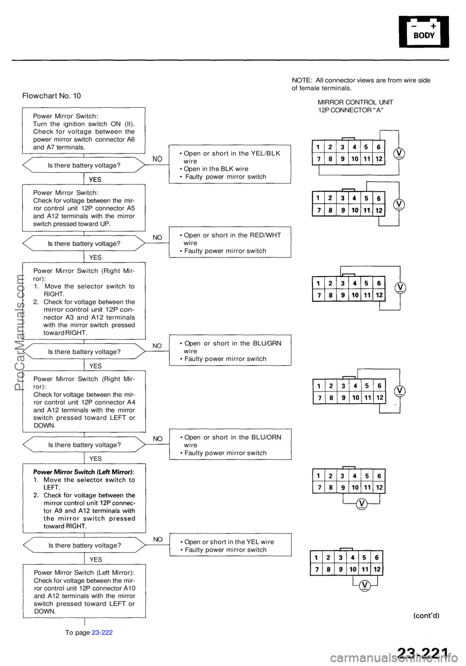
Flowchart No . 1 0
Powe r Mirro r Switch :
Tur n th e ignitio n switc h O N (II) .
Chec k fo r voltag e betwee n th e
powe r mirro r switc h connecto r A 6
an d A 7 terminals .
I s ther e batter y voltage ?
NO• Ope n o r shor t i n th e YEL/BL K
wir e
• Ope n in th e BL K wir e
• Fault y powe r mirro r switc h
Powe r Mirro r Switch :
Chec k fo r voltag e betwee n th e mir -
ro r contro l uni t 12 P connecto r A 5
an d A1 2 terminal s wit h th e mirro r
switc h presse d toward UP.
• Ope n o r shor t i n th e RED/WH T
wire• Fault y powe r mirro r switc h
NOIs ther e batter y voltage ?
YES
Powe r Mirro r Switc h (Righ t Mir -ror):1. Mov e th e selecto r switc h t oRIGHT .2. Chec k fo r voltag e betwee n th emirro r contro l uni t 12 P con -necto r A 3 an d A1 2 terminal s
wit h th e mirro r switc h presse d
towar d RIGHT .
• Ope n o r shor t i n th e BLU/GR N
wir e
• Fault y powe r mirro r switc h
NOIs ther e batter y voltage ?
YES
Powe r Mirro r Switc h (Righ t Mir -ror):Chec k fo r voltag e betwee n th e mir -
ro r contro l uni t 12 P connecto r A 4
an d A1 2 terminal s wit h th e mirro r
switc h presse d towar d LEF T o r
DOWN .
Is ther e batter y voltage ? •
Ope n o r shor t i n th e BLU/OR N
wir e
• Fault y powe r mirro r switc h
YES
NO
Powe r Mirro r Switc h (Lef t Mirror) :
Chec k fo r voltag e betwee n th e mir -
ro r contro l uni t 12 P connecto r A1 0
an d A1 2 terminal s wit h th e mirro r
switch presse d towar d LEF T o rDOWN .
To pag e 23-222
YE S
NOIs ther e batter y voltage ? •
Ope n o r shor t i n th e YE L wir e
• Fault y powe r mirro r switc h
NOTE: Al l connecto r view s ar e fro m wir e sid eof femal e terminals .
MIRRO R CONTRO L UNI T
12 P CONNECTO R "A "
ProCarManuals.com
Page 1626 of 1954

Substitute a known-goo d mirro r
contro l unit , an d recheck . I f th e
system s no w wor k OK , replac e
th e origina l mirro r contro l unit . •
Ope n o r shor t i n th e GR Y o r
BRN/WH T wire s
• Fault y lef t powe r mirro r posi -
tio n senso r
• Fault y mirro r contro l uni t
NOAr e voltage s a s specified ?
YES
Lef t Powe r Mirro r Positio n Sen -sor (Vertical) :
Chec k fo r voltag e betwee n th e mir -
ro r contro l uni t 16 P connecto r B1 4
and B1 6 terminals . A s th e mirro rtilts fro m up to down , th e voltag eshould chang e fro m abou t 1 V to3V .
YES
Are voltage s a s specified ?NO
• Ope n o r shor t i n th e GRN/WH T
o r BRN/WH T wire s
• Fault y lef t powe r mirro r posi -
tio n senso r
• Fault y mirro r contro l uni t
Lef
t Powe r Mirro r Positio n Sen -
so r (Horizontal) :
Chec k fo r voltag e betwee n th e
mirro r contro l uni t 16 P connecto r
B6 an d B1 6 terminals . A s th e mir -ror swing s fro m lef t t o right , th evoltag e shoul d chang e fro m
abou t 3 V to 1 V .
YE S
Are voltages as specified ?NO
• Ope n o r shor t i n th e GR Y o r
BRN/WH T wire s
• Fault y righ t powe r mirro r posi -
tion senso r• Fault y mirro r contro l uni t
Righ
t Powe r Mirro r Positio n Sen -
so r (Vertical) :
Chec k fo r voltag e betwee n th e mir -
ro r contro l uni t 16 P connecto r B1 5
and B1 6 terminals . A s th e mirro rtilts u p t o down , th e voltag eshould chang e fro m abou t 1 V to 3V .
YE S
Are voltages as specified ?
• Ope n o r shor t i n th e GR N o rBRN/WH T wire s
• Fault y righ t powe r mirro r posi -
tio n senso r
• Fault y mirro r contro l uni tNO
Righ t Powe r Mirro r Positio n Sen -
so r (Horizontal) :
Chec k fo r voltag e betwee n th e mir -
ror contro l uni t 16 P connecto r B 7an d B1 6 terminals . A s th e mirro rswings fro m righ t t o left , th e volt -
ag e shoul d chang e fro m abou t
3Vto 1 V .
Fro
m pag e 23-222
NOTE: Al l connecto r view s ar e fro m wir e sid e
of femal e terminals .
MIRROR CONTRO L UNI T
16 P CONNECTO R "B "
(cont'd )
ProCarManuals.com
Page 1633 of 1954
Driving Positio n Memor y Syste m (DPMS )
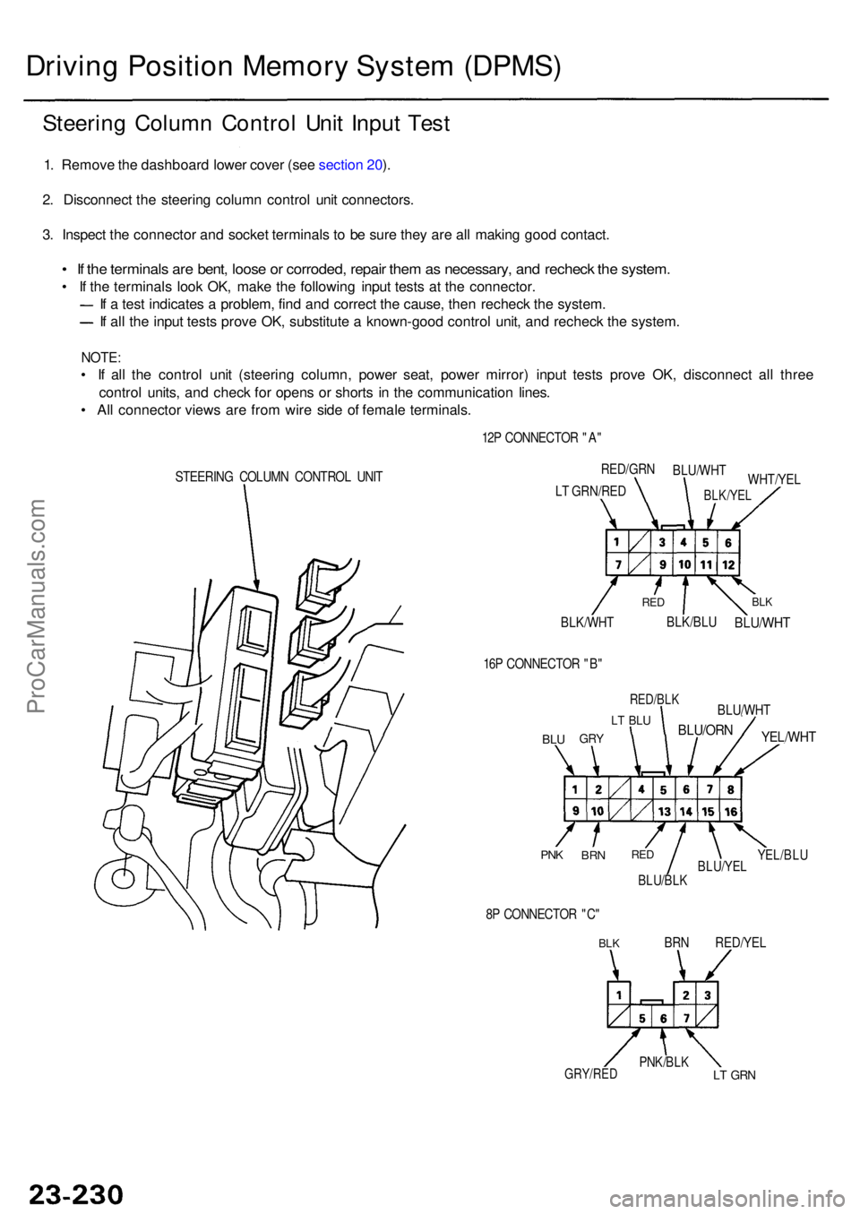
Steering Colum n Contro l Uni t Inpu t Tes t
1. Remov e th e dashboar d lowe r cove r (se e sectio n 20 ).
2 . Disconnec t th e steerin g colum n contro l uni t connectors .
3 . Inspec t th e connecto r an d socke t terminal s t o b e sur e the y ar e al l makin g goo d contact .
• I f th e terminal s ar e bent , loos e o r corroded , repai r the m as necessary , an d rechec k th e system .
• I f th e terminal s loo k OK , mak e th e followin g inpu t test s a t th e connector .
I f a tes t indicate s a problem , fin d an d correc t th e cause , the n rechec k th e system .
If al l th e inpu t test s prov e OK , substitut e a known-goo d contro l unit , an d rechec k th e system .
NOTE:
• I f al l th e contro l uni t (steerin g column , powe r seat , powe r mirror ) inpu t test s prov e OK , disconnec t al l thre e
contro l units , an d chec k fo r open s o r short s i n th e communicatio n lines .
• Al l connecto r view s ar e fro m wir e sid e o f femal e terminals .
STEERING COLUM N CONTRO L UNI T 12
P CONNECTO R "A "
BLK/WH T
BLK/BLUBLU/WH T
BLKRE D
WHT/YE L
RED/GR
N
BLU/WH T
BLK/YELLT GRN/RE D
16 P CONNECTO R "B "
BLUGR Y
LT BL U
RED/BL K
BLU/ORN
BLU/WH T
YEL/WHT
YEL/BLUBLU/YE LBLU/BLK
REDBR NPNK
8P CONNECTO R "C "
BLKBR N RED/YE L
LT GR NPNK/BL KGRY/RED
ProCarManuals.com
Page 1637 of 1954
Driving Positio n Memor y Syste m (DPMS )
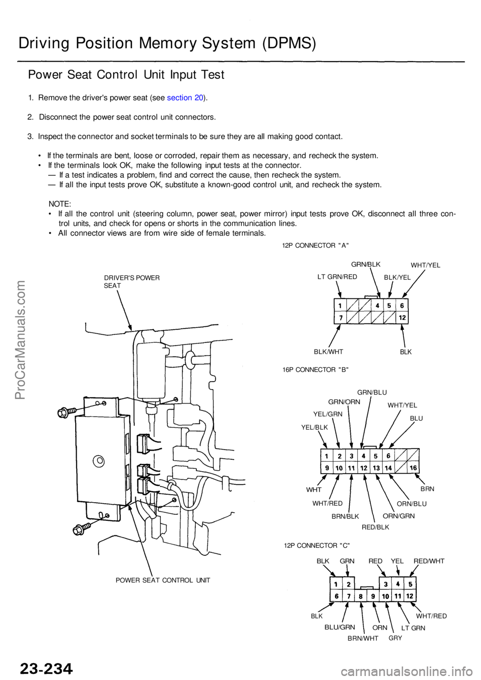
Power Sea t Contro l Uni t Inpu t Tes t
1. Remov e th e driver' s powe r sea t (se e sectio n 20 ).
2 . Disconnec t th e powe r sea t contro l uni t connectors .
3 . Inspec t th e connecto r an d socke t terminal s t o b e sur e the y ar e al l makin g goo d contact .
• I f th e terminal s ar e bent , loos e o r corroded , repai r the m a s necessary , an d rechec k th e system .
• I f th e terminal s loo k OK , mak e th e followin g inpu t test s a t th e connector .
I f a tes t indicate s a problem , fin d an d correc t th e cause , the n rechec k th e system .
If al l th e inpu t test s prov e OK , substitut e a known-goo d contro l unit , an d rechec k th e system .
NOTE:
• I f al l th e contro l uni t (steerin g column , powe r seat , powe r mirror ) inpu t test s prov e OK , disconnec t al l thre e con -
tro l units , an d chec k fo r open s o r short s i n th e communicatio n lines .
• Al l connecto r view s ar e fro m wir e sid e o f femal e terminals .
12P CONNECTO R "A "
POWE R SEA T CONTRO L UNI T
DRIVER'
S POWE R
SEA T
BLK/WHT
BLK
LT GRN/RE D
GRN/BLK
BLK/YE L
WHT/YE L
16 P CONNECTO R "B "
GRN/BL U
WHT/YE L
BLU
GRN/OR N
YEL/GRN
YEL/BLK
WHT
WHT/RE D
BRN
ORN/BL U
ORN/GR N
RED/BLK
BRN/BLK
12 P CONNECTO R "C "
BLK GR N RE D YE L RED/WH T
BLK
BLU/GR N
BRN/WH T
ORNLT GR N
WHT/RE D
GRY
ProCarManuals.com
Page 1641 of 1954
Driving Positio n Memor y Syste m (DPMS )
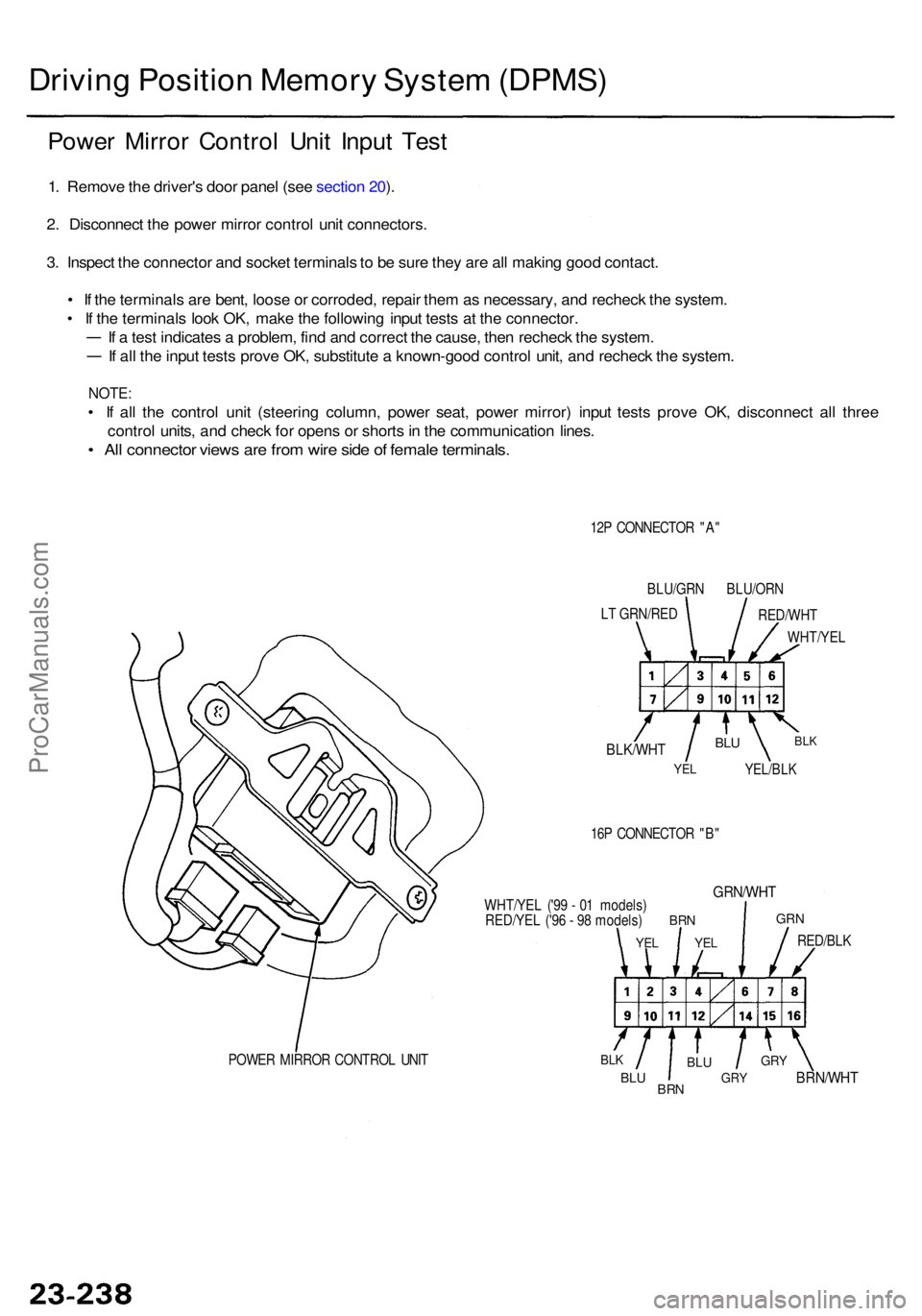
Power Mirro r Contro l Uni t Inpu t Tes t
1. Remov e th e driver' s doo r pane l (se e sectio n 20 ).
2 . Disconnec t th e powe r mirro r contro l uni t connectors .
3 . Inspec t th e connecto r an d socke t terminal s to b e sur e the y ar e al l makin g goo d contact .
• I f th e terminal s ar e bent , loos e o r corroded , repai r the m as necessary , an d rechec k th e system .
• I f th e terminal s loo k OK , mak e th e followin g inpu t test s a t th e connector .
I f a tes t indicate s a problem , fin d an d correc t th e cause , the n rechec k th e system .
If al l th e inpu t test s prov e OK , substitut e a known-goo d contro l unit , an d rechec k th e system .
NOTE:
• I f al l th e contro l uni t (steerin g column , powe r seat , powe r mirror ) inpu t test s prov e OK , disconnec t al l thre e
contro l units , an d chec k fo r open s o r short s in th e communicatio n lines .
• Al l connecto r view s ar e fro m wir e sid e o f femal e terminals .
12P CONNECTO R "A "
BLU/GR N BLU/OR N
L T GRN/RE D
RED/WHT
WHT/YE L
BLK/WHT
YEL
BLU
YEL/BL K
BLK
16P CONNECTO R "B "
WHT/YE L ('9 9 - 0 1 models )
RED/YE L ('9 6 - 9 8 models )
YEL
BR N
YEL
GRN/WH T
GRN
RED/BL K
BRN/WH T
GRY
GR YBLU
BR NBLU
BLKPOWE R MIRRO R CONTRO L UNI T
ProCarManuals.com
Page 1721 of 1954
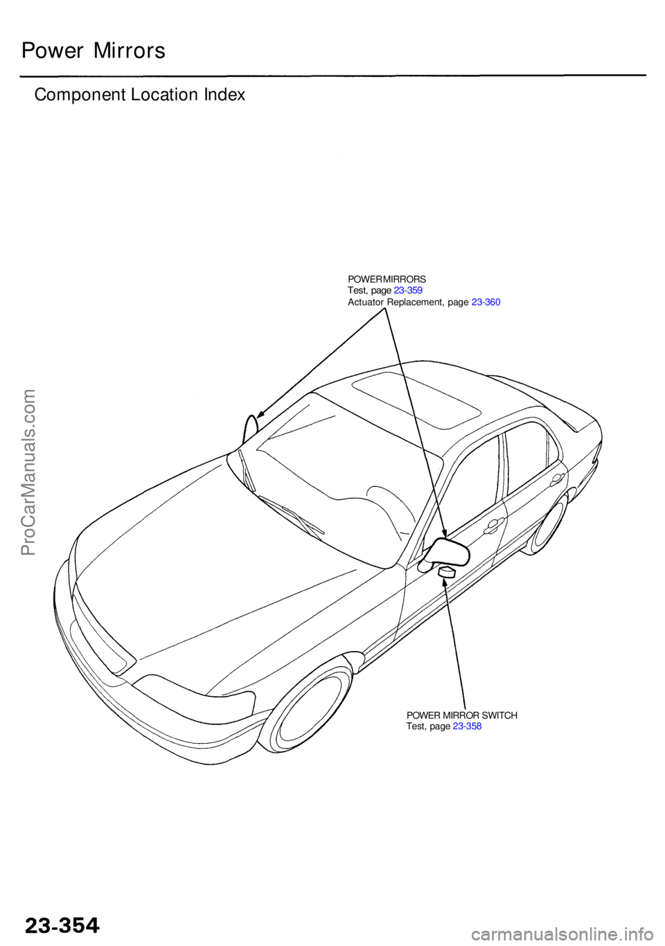
POWER MIRRO R SWITC H
Test , pag e 23-35 8
Powe r Mirror s
Componen t Locatio n Inde x
POWE R MIRROR STest, pag e 23-35 9Actuato r Replacement , pag e 23-36 0
ProCarManuals.com
Page 1722 of 1954
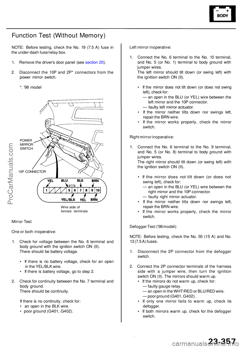
Function Tes t (Withou t Memory )
NOTE: Befor e testing , chec k th e No . 1 9 (7. 5 A ) fus e i n
th e under-das h fuse/rela y box .
1 . Remov e th e driver' s doo r pane l (se e sectio n 20 ).
2 . Disconnec t th e 10 P an d 2P * connector s fro m th e
powe r mirro r switch .
* : '9 8 mode l
POWE RMIRRO RSWITCH
10 P CONNECTO R
Mirror Tes t
On e o r bot h inoperative :
1 . Chec k fo r voltag e betwee n th e No . 6 termina l an d
bod y groun d wit h th e ignitio n switc h O N (II) .
Ther e shoul d b e batter y voltage .
• I f ther e i s n o batter y voltage , chec k fo r a n ope n
i n th e YEL/BL K wire .
• I f ther e is batter y voltage , g o to ste p 2 .
2 . Chec k fo r continuit y betwee n th e No . 7 termina l an d
bod y ground .
Ther e shoul d b e continuity .
I f ther e is n o continuity , chec k for :
• a n ope n in th e BL K wire .
• poo r groun d (G401 , G402) . Lef
t mirro r inoperative :
1 . Connec t th e No . 6 termina l t o th e No . 1 0 terminal ,
an d No . 5 (o r No . 1 ) termina l t o bod y groun d wit h
jumpe r wires .
Th e lef t mirro r shoul d til t dow n (o r swin g left ) wit h
th e ignitio n switc h O N (II) .
• I f th e mirro r doe s no t til t dow n (o r doe s no t swin g
left) , chec k for :
— an ope n in th e BL U (o r YEL ) wir e betwee n th e
lef t mirro r an d th e 10 P connector .
— fault y lef t mirro r actuator .
• I f th e mirro r neithe r tilt s dow n no r swing s left ,
repai r th e BR N wire .
• I f th e mirro r work s properly , chec k th e mirro r
switch .
Righ t mirro r inoperative :
1 . Connec t th e No . 6 termina l t o th e No . 9 terminal ,
an d No . 5 (o r No . 8 ) termina l t o bod y groun d wit h
jumpe r wires .
Th e righ t mirro r shoul d til t dow n (o r swin g left ) wit h
th e ignitio n switc h O N (II) .
• I f th e mirro r doe s no t til t dow n (o r doe s no t
swin g left) , chec k for :
— an ope n in th e BL U (o r YEL ) wir e betwee n th e
righ t mirro r an d th e 10 P connector .
— fault y righ t mirro r actuator .
• I f th e mirro r neithe r tilt s dow n no r swing s left ,
repai r th e BR N wire .
• I f th e mirro r work s properly , chec k th e mirro r
switch .
Defogge r Tes t ('9 8 model) :
NOTE : Befor e testing , chec k th e No . 5 5 (1 5 A ) an d No .
1 3 (7. 5 A ) fuses .
1 . Disconnec t th e 2 P connecto r fro m th e defogge r
switch .
2 . Connec t th e 2 P connecto r terminal s o f th e harnes s
sid e wit h a jumpe r wire , the n tur n th e ignitio n
switc h O N (II) . Th e mirror s shoul d war m up .
• I f th e mirror s d o no t war m up , chec k for :
— fault y gaug e relay .
— an ope n in th e WHT/RE D o r BLU/RE D wire .
— poo r groun d (G401 , G402) .
• I f onl y on e mirro r fail s t o war m up , chec k it s
defogger .
• I f bot h mirror s war m up , chec k fo r th e defogge r
switch .
Wire sid e o ffemal e terminal s
ProCarManuals.com