1996 ACURA RL KA9 mirror
[x] Cancel search: mirrorPage 1331 of 1954
Rearview Mirror Removal
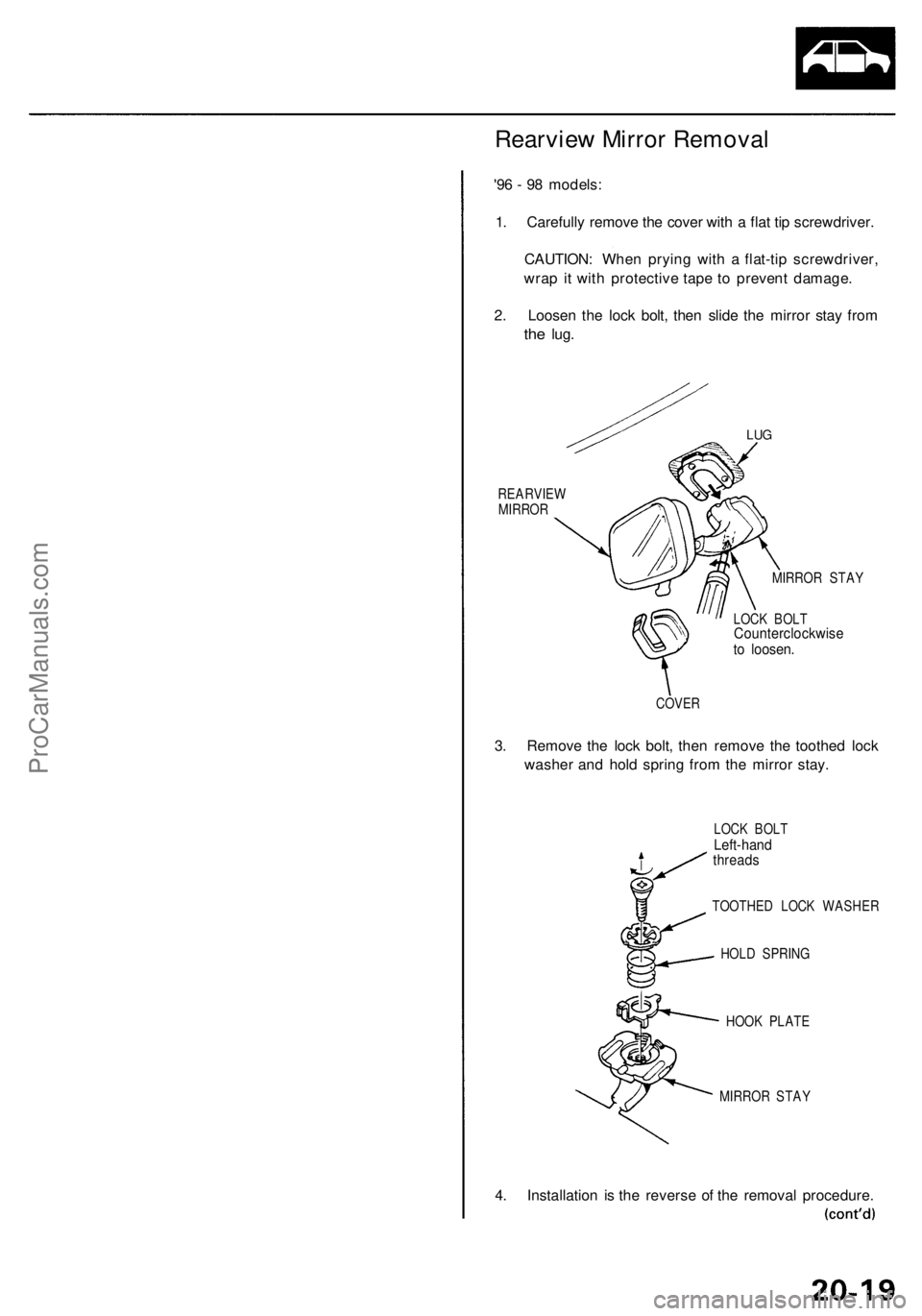
'96 - 98 models:
1. Carefully remove the cover with a flat tip screwdriver.
CAUTION: When prying with a flat-tip screwdriver,
wrap it with protective tape to prevent damage.
2. Loosen the lock bolt, then slide the mirror stay from
the
lug.
LUG
REARVIEW
MIRROR
MIRROR STAY
LOCK BOLT
Counterclockwise
to loosen.
COVER
3. Remove the lock bolt, then remove the toothed lock
washer and hold spring from the mirror stay.
LOCK BOLT
Left-hand
threads
TOOTHED LOCK WASHER
HOLD SPRING
HOOK PLATE
MIRROR STAY
4. Installation is the reverse of the removal procedure.ProCarManuals.com
Page 1332 of 1954
Mirrors
Rearvie w Mirro r Remova l (cont'd )
'99 - 0 1 model s (Wit h automati c dimming) :
CAUTION : Whe n pryin g wit h a flat-ti p screwdriver ,
wra p it wit h protectiv e tap e t o preven t damage .
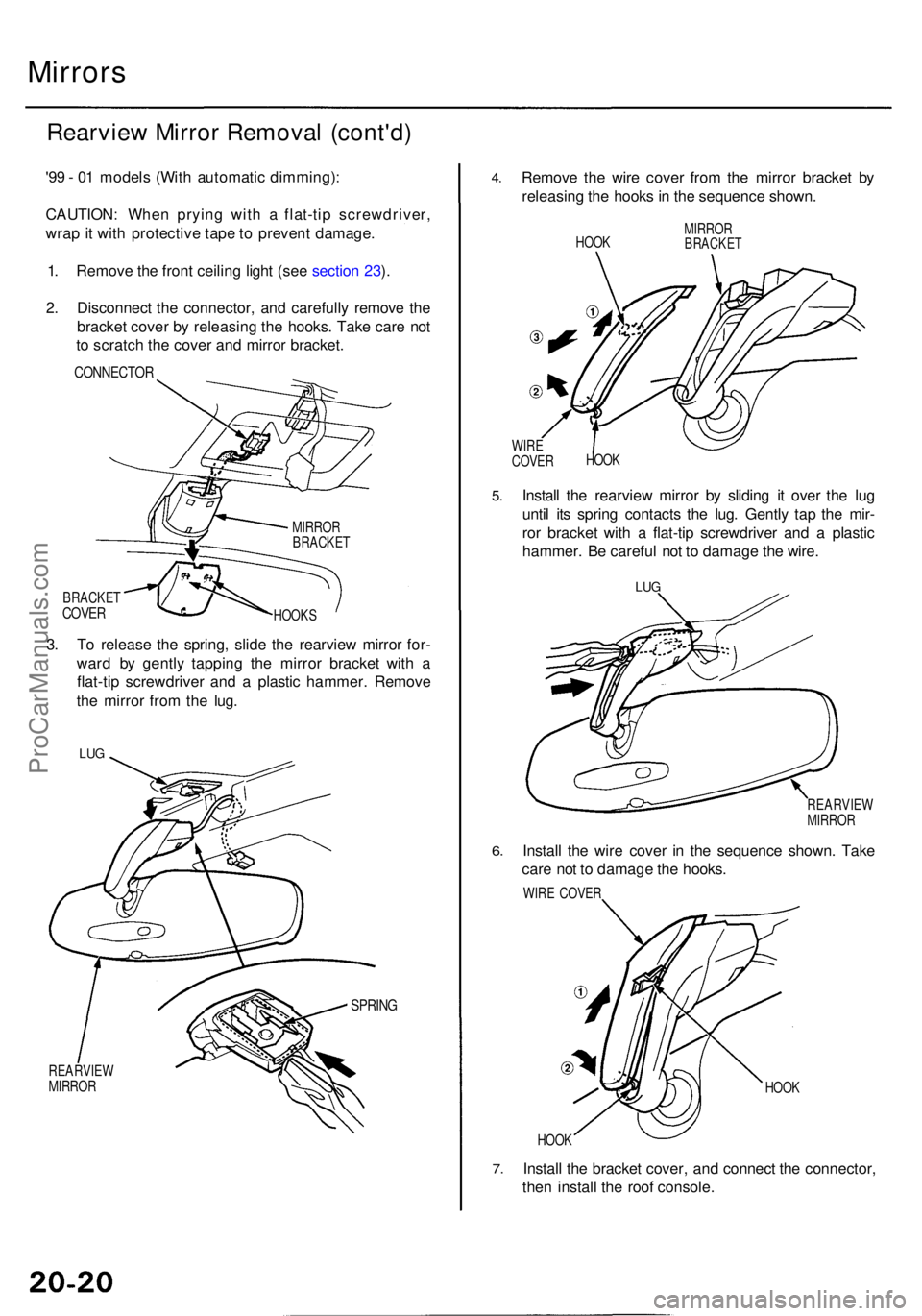
1 . Remov e th e fron t ceilin g ligh t (se e sectio n 23 ).
2 . Disconnec t th e connector , an d carefull y remov e th e
bracke t cove r b y releasin g th e hooks . Tak e car e no t
t o scratc h th e cove r an d mirro r bracket .
CONNECTO R
BRACKETCOVERHOOK S
3. T o releas e th e spring , slid e th e rearvie w mirro r for -
war d b y gentl y tappin g th e mirro r bracke t wit h a
flat-ti p screwdrive r an d a plasti c hammer . Remov e
th e mirro r fro m th e lug .
LUG
SPRIN G
REARVIE W
MIRRO R
4.Remov e th e wir e cove r fro m th e mirro r bracke t b y
releasin g th e hook s in th e sequenc e shown .
HOOK MIRRO
RBRACKE T
WIRE
COVE R HOO
K
5.Instal l th e rearvie w mirro r b y slidin g i t ove r th e lu g
unti l it s sprin g contact s th e lug . Gentl y ta p th e mir -
ro r bracke t wit h a flat-ti p screwdrive r an d a plasti c
hammer. Be carefu l no t t o damag e th e wire .
LUG
6.
REARVIE W
MIRRO R
Install th e wir e cove r i n th e sequenc e shown . Tak e
car e no t t o damag e th e hooks .
WIRE COVE R
HOOK
7.
HOO K
Instal l th e bracke t cover , an d connec t th e connector ,
the n instal l th e roo f console .
MIRRORBRACKE T
ProCarManuals.com
Page 1561 of 1954
Interior Light s
Vanity Mirro r Ligh t Tes t
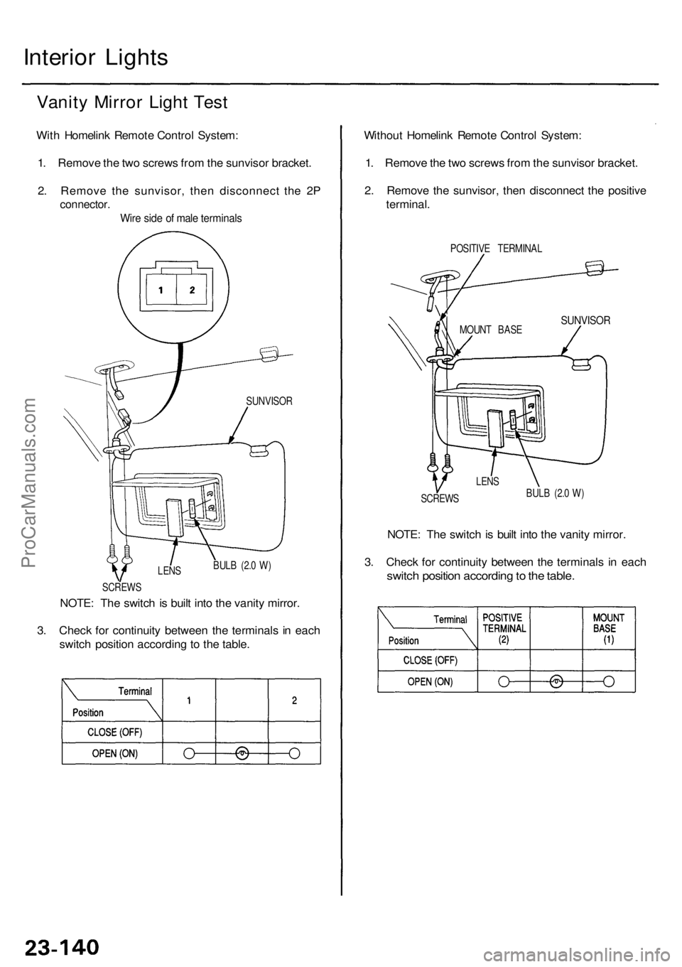
With Homelin k Remot e Contro l System :
1 . Remov e th e tw o screw s fro m th e sunviso r bracket .
2 . Remov e th e sunvisor , the n disconnec t th e 2 P
connector .
Wire sid e o f mal e terminal s
NOTE: Th e switc h is buil t int o th e vanit y mirror .
3 . Chec k fo r continuit y betwee n th e terminal s i n eac h
switc h positio n accordin g t o th e table . Withou
t Homelin k Remot e Contro l System :
1 . Remov e th e tw o screw s fro m th e sunviso r bracket .
2 . Remov e th e sunvisor , the n disconnec t th e positiv e
terminal .
POSITIV E TERMINA L
SUNVISORMOUNT BAS E
SCREW S
SUNVISO
R
LENS
BULB (2. 0 W )
NOTE : Th e switc h is buil t int o th e vanit y mirror .
3 . Chec k fo r continuit y betwee n th e terminal s i n eac h
switc h positio n accordin g to th e table .BULB (2. 0 W )
LEN S
SCREW S
ProCarManuals.com
Page 1589 of 1954
Automatic Insid e Dimmin g Mirro r
Test/Replacemen t
NOTE: Befor e testing , chec k th e No . 1 3 (7. 5 A ) fuse .
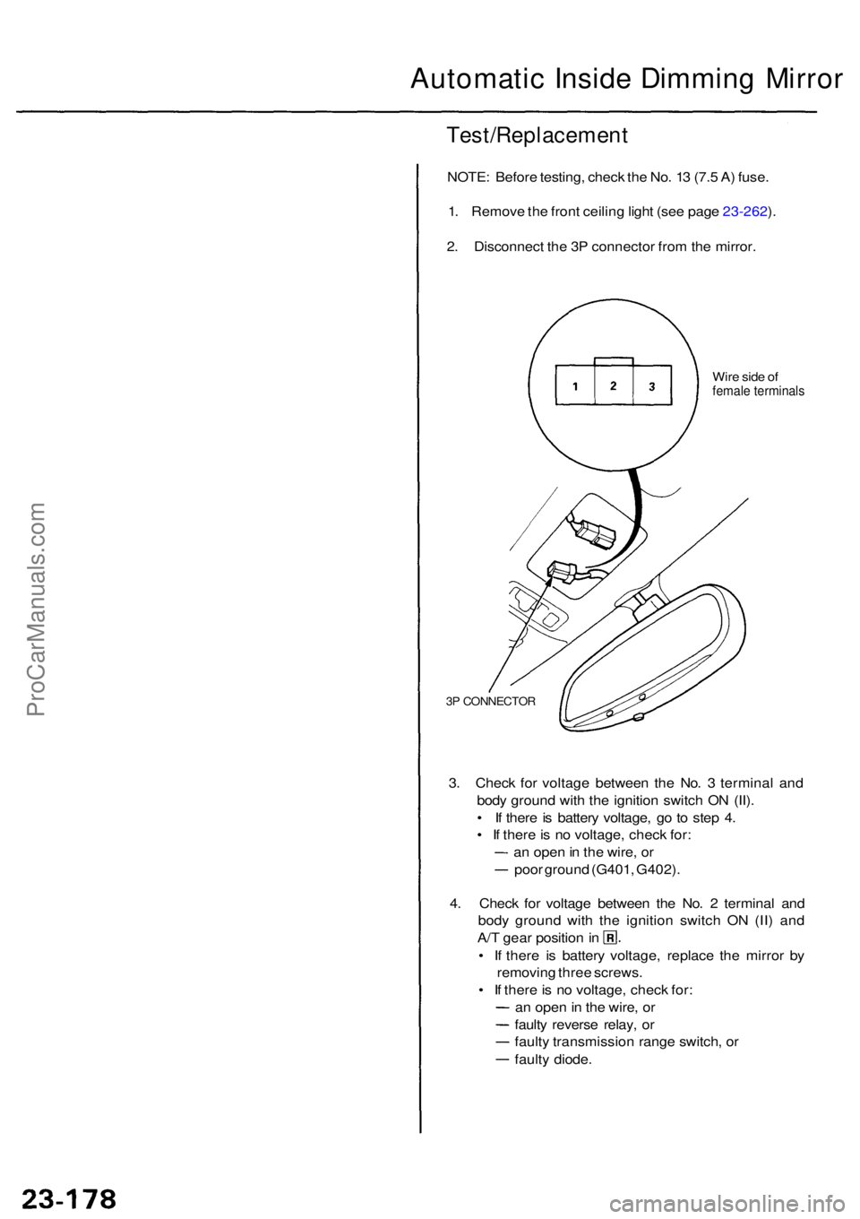
1 . Remov e th e fron t ceilin g ligh t (se e pag e 23-262 ).
2 . Disconnec t th e 3 P connecto r fro m th e mirror .
Wire sid e o ffemal e terminal s
3P CONNECTO R
3. Chec k fo r voltag e betwee n th e No . 3 termina l an d
bod y groun d wit h th e ignitio n switc h O N (II) .
• I f ther e is batter y voltage , g o t o ste p 4 .
• I f ther e is n o voltage , chec k for :
a n ope n in th e wire , o r
poo r groun d (G401 , G402) .
4 . Chec k fo r voltag e betwee n th e No . 2 termina l an d
bod y groun d wit h th e ignitio n switc h O N (II ) an d
A/T gea r positio n in
• I f ther e i s batter y voltage , replac e th e mirro r b y
removin g thre e screws .
• I f ther e is n o voltage , chec k for :
a n ope n in th e wire , o r
fault y revers e relay , o r
fault y transmissio n rang e switch , o r
fault y diode .
ProCarManuals.com
Page 1599 of 1954
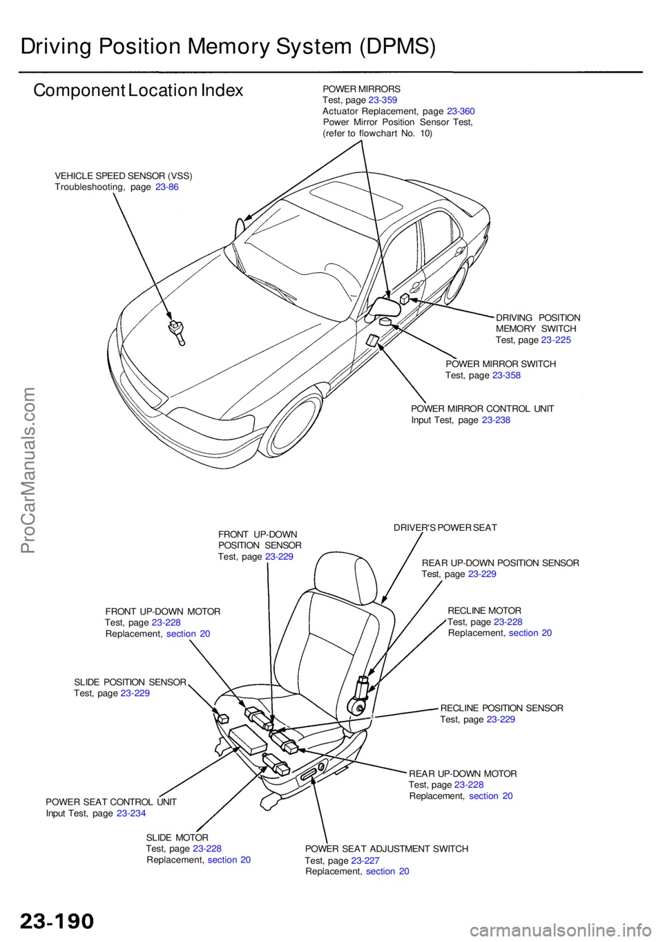
Driving Positio n Memor y Syste m (DPMS )
Componen t Locatio n Inde x
VEHICL E SPEE D SENSO R (VSS )
Troubleshooting , pag e 23-8 6 POWE
R MIRROR S
Test , pag e 23-35 9
Actuato r Replacement , pag e 23-36 0
Powe r Mirro r Positio n Senso r Test ,
(refe r t o flowchar t No . 10 )
DRIVING POSITIO N
MEMOR Y SWITC H
Test , pag e 23-22 5
POWE R MIRRO R SWITC H
Test , pag e 23-35 8
POWE R MIRRO R CONTRO L UNI T
Inpu t Test , pag e 23-23 8
FRON T UP-DOW N
POSITIO N SENSO R
Test , pag e 23-22 9 DRIVER'
S POWE R SEA T
REA R UP-DOW N POSITIO N SENSO R
Test , pag e 23-22 9
RECLIN E MOTO R
Test , pag e 23-22 8
Replacement , sectio n 2 0
RECLIN E POSITIO N SENSO R
Test , pag e 23-22 9
REA R UP-DOW N MOTO R
Test , pag e 23-22 8
Replacement , sectio n 2 0
POWE R SEA T ADJUSTMEN T SWITC H
Test , pag e 23-22 7
Replacement , sectio n 2 0
SLID
E MOTO R
Test , pag e 23-22 8
Replacement , sectio n 2 0
POWE
R SEA T CONTRO L UNI T
Inpu t Test , pag e 23-23 4
SLID
E POSITIO N SENSO R
Test , pag e 23-22 9
FRON
T UP-DOW N MOTO R
Test , pag e 23-22 8
Replacement , sectio n 2 0
ProCarManuals.com
Page 1601 of 1954
Driving Positio n Memor y Syste m (DPMS )
Descriptio n
The driver' s seat , th e powe r mirror s an d th e steerin g column , whos e position s ar e determine d th e driver' s position , hav e
a memor y feature . Th e sea t adjustments , th e mirro r adjustments , an d th e steerin g colum n adjustment s can be regulate d
separately . Al l o f adjustment s ca n b e memorize d b y th e pressin g th e MEM O butto n o n th e drivin g positio n memor y
switch , an d the n pressin g on e o f th e tw o positio n button s withi n 5 seconds . Pressin g th e appropriat e positio n butto n wil l
mov e th e seat , th e mirro r an d th e steerin g colum n t o th e positio n memorize d fo r drive r 1 o r drive r 2 , eliminatin g manua l
adjustment s whe n changin g drivers .
NOTE : Disconnectin g th e batter y wil l cance l th e memorize d positions .
STEERIN G COLUM N POSITIO N SENSOR S
B y mean s o f th e variabl e resistor-typ e til t positio n senso r an d extend-retrac t positio n sensor , th e steerin g colum n contro l
uni t detect s th e voltag e change s cause d b y th e movement s o f th e steerin g column . Thes e voltag e change s ar e store d in
memory , an d th e steerin g colum n positio n is memorized .
POWE R SEA T POSITIO N SENSOR S
Eac h moto r ha s a ree d switc h senso r whic h detect s moto r rotatio n an d send s a puls e to th e powe r sea t contro l uni t whe n
th e moto r rotates . Th e contro l uni t store s th e numbe r o f pulse s i n it s memory , an d th e sea t positio n is memorized .
POWE R MIRRO R POSITIO N SENSOR S
B y mean s o f a Hall-effec t typ e til t positio n senso r an d swin g positio n sensor , th e powe r mirro r contro l uni t detect s th e
voltag e change s cause d b y th e movement s o f th e mirrors .
Thes e voltag e change s ar e store d in memory , an d th e powe r mirro r position s ar e memorized .
"AUTO " SWITC H FUNCTIO N
Whe n th e ignitio n ke y i s pulle d ou t (ignitio n switc h turne d OFF ) wit h th e AUT O switc h i n th e steerin g colum n switc h O N
and th e vehicl e parke d (shif t leve r i n th e steerin g colum n wil l automaticall y mov e t o th e highes t til t positio n an d full y
retracte d positio n t o eas e exi t fro m th e vehicle .
Whe n th e ignitio n ke y i s inserte d int o th e ignitio n ke y switc h wit h th e AUT O switc h O N an d th e vehicl e parke d (shif t leve r
in th e steerin g colum n wil l automaticall y mov e bac k t o th e previou s position .
MEMOR Y RETRIEV E
When on e o f th e tw o button s o n th e drivin g positio n memor y switc h i s presse d wit h th e vehicl e parke d (shif t leve r i n
th e seat , th e mirror , an d th e steerin g colum n mov e t o th e memorize d positions .
ProCarManuals.com
Page 1605 of 1954
Driving Positio n Memor y Syste m (DPMS )
Troubleshootin g Guid e
After completin g th e pre-troubleshootin g test s (se e pag e 23-204 ), selec t th e flowchart(s ) liste d o n th e nex t pag e fo r th e
symptom(s ) yo u wan t t o troubleshoot . I f th e symptom(s ) ar e relate d t o automati c adjusting , firs t rea d th e explanatio n fo r
th e automati c adjustmen t modes .
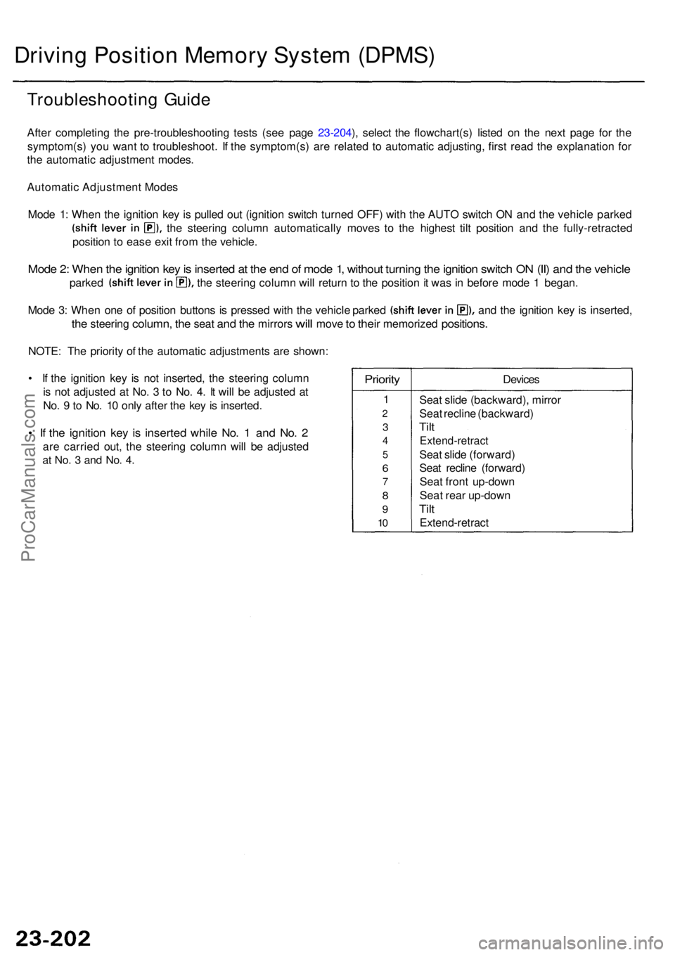
Automati c Adjustmen t Mode s
Mod e 1 : Whe n th e ignitio n ke y i s pulle d ou t (ignitio n switc h turne d OFF ) wit h th e AUT O switc h O N an d th e vehicl e parke d
the steerin g colum n automaticall y move s t o th e highes t til t positio n an d th e fully-retracte d
positio n t o eas e exi t fro m th e vehicle .
Mode 2 : Whe n th e ignitio n ke y is inserte d a t th e en d o f mod e 1 , withou t turnin g th e ignitio n switc h O N (II ) an d th e vehicl e
parked th e steerin g colum n wil l retur n t o th e positio n it wa s in befor e mod e 1 began .
Mode 3 : Whe n on e o f positio n button s i s presse d wit h th e vehicl e parke d an d th e ignitio n ke y i s inserted ,
the steerin g column , the sea t and th e mirror s will mov e to thei r memorize d positions.
NOTE: Th e priorit y o f th e automati c adjustment s ar e shown :
• I f th e ignitio n ke y i s no t inserted , th e steerin g colum n
i s no t adjuste d a t No . 3 to No . 4 . I t wil l b e adjuste d a t
No . 9 to No . 1 0 onl y afte r th e ke y is inserted .
• I f th e ignitio n ke y i s inserte d whil e No . 1 an d No . 2
ar e carrie d out , th e steerin g colum n wil l b e adjuste d
at No . 3 an d No . 4 .
Priorit y
1
2
3
4
5
6
7
8
9
10
Device s
Sea t slid e (backward) , mirro r
Sea t reclin e (backward )
Tilt
Extend-retrac t
Seat slid e (forward )
Sea t reclin e (forward )
Sea t fron t up-dow n
Sea t rea r up-dow n
Tilt
Extend-retrac t
ProCarManuals.com
Page 1615 of 1954
Driving Positio n Memor y Syste m (DPMS )
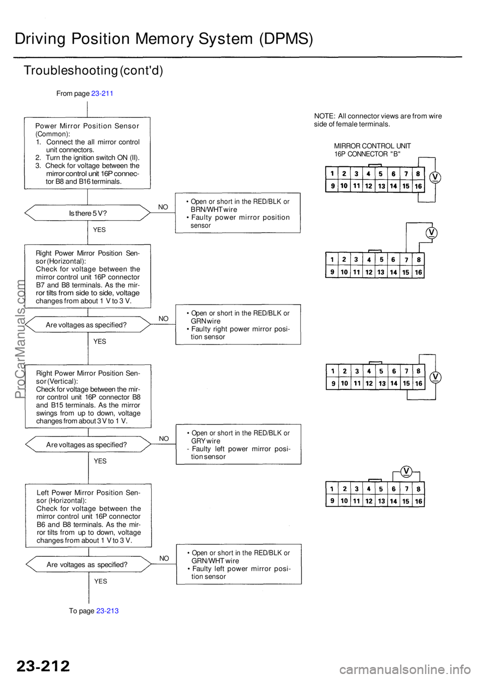
Troubleshootin g (cont'd )
From pag e 23-211
Powe r Mirro r Positio n Senso r
(Common) :1. Connec t th e al l mirro r contro l
uni t connectors .
2 . Tur n th e ignitio n switc h O N (II) .
3 . Chec k fo r voltag e betwee n th e
mirro r contro l uni t 16 P connec -tor B 8 an d B1 6 terminals .
Is ther e 5 V ?NO• Ope n o r shor t i n th e RED/BL K o rBRN/WH T wir e
• Fault y powe r mirro r positio n
sensorYES
Righ t Powe r Mirro r Positio n Sen -
so r (Horizontal) :
Chec k fo r voltag e betwee n th e
mirro r control unit 16 P connecto r
B 7 an d B 8 terminals . A s th e mir -
ror tilt s fro m sid e to side , voltag echange s fro m abou t 1 V to 3 V .
• Ope n o r shor t i n th e RED/BL K o rGR N wir e
• Fault y righ t powe r mirro r posi -
tion senso r
Are voltage s a s specified ?NO
YE S
Righ t Powe r Mirro r Positio n Sen -
so r (Vertical) :
Chec k fo r voltag e betwee n th e mir -
ro r contro l uni t 16 P connecto r B 8
an d B1 5 terminals . A s th e mirro r
swing s fro m u p t o down , voltag e
change s fro m abou t 3 V to 1 V .
Ar e voltage s a s specified ?
• Ope n o r shor t i n th e RED/BL K o rGR Y wir e
- Fault y lef t powe r mirro r posi -
tio n senso rNO
YE S
Lef t Powe r Mirro r Positio n Sen -sor (Horizontal) :Check fo r voltag e betwee n th e
mirro r contro l uni t 16 P connecto r
B 6 an d B 8 terminals . A s th e mir -
ro r tilt s fro m u p t o down , voltag e
change s fro m abou t 1 V to 3 V .
Ar e voltage s a s specified ?
NO• Ope n o r shor t i n th e RED/BL K o rGRN/WH T wir e
• Fault y lef t powe r mirro r posi -
tion senso rYES
To pag e 23-213 NOTE
: Al l connecto r view s ar e fro m wir e
sid e o f femal e terminals .
MIRROR CONTRO L UNI T16P CONNECTO R "B "
ProCarManuals.com