1996 ACURA RL KA9 fuel pressure
[x] Cancel search: fuel pressurePage 147 of 1954
![ACURA RL KA9 1996 Service Repair Manual
Fuel Supply System
The HDS or the scan tool indicates Diagnostic Trouble Code (DTC) P0171: The fuel system is too lean [Right
Bank (Bank 1)].
The HDS or the scan tool indicates Diagnostic Trouble ACURA RL KA9 1996 Service Repair Manual
Fuel Supply System
The HDS or the scan tool indicates Diagnostic Trouble Code (DTC) P0171: The fuel system is too lean [Right
Bank (Bank 1)].
The HDS or the scan tool indicates Diagnostic Trouble](/manual-img/32/56992/w960_56992-146.png)
Fuel Supply System
The HDS or the scan tool indicates Diagnostic Trouble Code (DTC) P0171: The fuel system is too lean [Right
Bank (Bank 1)].
The HDS or the scan tool indicates Diagnostic Trouble Code (DTC) P0172: The fuel system is too rich [Right
Bank (Bank 1)].
The HDS or the scan tool indicates Diagnostic Trouble Code (DTC) P0174: The fuel system is too lean [Left Bank
(Bank 2)].
The HDS or the scan tool indicates Diagnostic Trouble Code (DTC) P0175: The fuel system is too rich [Left Bank
(Bank 2)].
Description
By monitoring the Long Term Fuel Trim, long term malfunctions in the fuel system will be detected.
If a
malfunction
has
been detected
during
two
consecutive
trips,
the MIL
will
come
on and DTC
P0171,
P0172, P0174
and/or P0175 will be stored.
NOTE: If some of the DTCs listed below are stored at the same time as DTC P0171, P0172, P0174 and/or P0175, trou-
bleshoot those DTCs first, then troubleshoot DTC P0171, P0172, P0174 and/or P0175.
P0107, P0108, P1128, P1129: MAP Sensor
P0135: Right Primary HO2S Heater (Bank 1, Sensor 1)
P0137, P0138: Secondary HO2S (Sensor 2)
P0141: Secondary HO2S Heater (Sensor 2)
P0155: Left Primary H02S Heater (Bank 2, Sensor 1)
P0401: EGR Flow Insufficient
P0404: EGR Valve Lift Insufficient
P0406: EGR Valve Position Sensor High Voltage
Possible Cause
Fuel Pump insufficient flow/pressure
Fuel Feed Line clogged, leaking
Fuel Pressure Regulator stuck open
Fuel Filter clogged
Injector clogged, air inclusion
Gasoline doesn't meet Owner's Manual spec.
Primary H02S (Sensor 1) deteriorated
EGR System insufficient flow
Exhaust leak
Fuel Pressure Regulator clogged, stuck closed
Fuel Return Pipe clogged
Injector leaking
Gasoline doesn't meet Owner's Manual spec.
Primary HO2S (Sensor 1) deteriorated
EGR System malfunction (too much flow)
EVAP Canister Purge Valve leaking, stuck opened
(cont'd)ProCarManuals.com
Page 148 of 1954

PGM-FI System
Fuel Supply System (cont'd)
Troubleshooting Flowchart
— The MIL has been reported on.
— DTC P0171, P0172, P0174 and/
or P0175 are stored.
Check the fuel pressure.
Is the fuel pressure OK?
NO
YES
Check the Primary HO2S:
1. Start the engine. Hold the
engine at 3,000 rpm with no
load (in Park or neutral) until
the radiator fan comes on.
2. Check the right primary or left
primary* H02S (Sensor 1) out-
put voltage with the HDS or
the scan tool.
Is the fuel pressure too high
or too low?
Check the fuel pressure regulator
and fuel return pipe.
LOW
Check the fuel pump, fuel feed
pipe, fuel filter, and fuel pressure
regulator.
Does it stay at less than 0.3 V
or more than 0.6V?
Replace the HO2S.
NO
Check for a sticking or leaking
EVAP canister purge valve:
With a vacuum pump, apply vacu-
um to the EVAP canister purge
valve from the intake manifold
side.
Does it hold vacuum?
Replace the EVAP canister purge
valve.
YES
Check the EGR system. If it is OK,
replace the fuel injectors.
*: P0174 or P0175ProCarManuals.com
Page 149 of 1954

Random Misfir e
The HD S o r th e sca n too l indicate s Diagnosti c Troubl e Cod e (DTC ) P0300 , an d
som e o f P120 1 - P120 6 o r som e o f P130 1 - P1306 : Rando m misfire .
Descriptio n
Misfire detectio n i s accomplishe d b y monitorin g th e voltag e o f th e spar k plu g wit h th e spar k plu g voltag e senso r whic h i s
buil t i n to th e ignitio n coil .
If misfirin g stron g enoug h t o damag e th e catalys t i s detected , th e MI L wil l blin k durin g th e tim e o f it s occurrence , an d DT C
P0300 , som e
of DTC s P120 1 throug h P1206 or som e of DTC s P130 1 throug h P1306 will be stored . Then , after misfir e has
ceased , th e MI L wil l com e o n an d sta y o n wheneve r th e ignitio n switc h is O N (II) .
I f misfirin g tha t increase s emission s i s detecte d during two consecutiv e drivin g cycles , th e MI L wil l com e on , an d DT C
P0300 , som e o f DTC s P120 1 throug h P120 6 o r som e o f DTC s P130 1 throug h P130 6 wil l b e stored .
NOTE : I f som e o f th e DTC s liste d belo w ar e store d a t th e sam e tim e a s a misfir e DTC , troubleshoo t thos e DTC s first , the n
troubleshoo t th e misfir e DTC .
P1128 , P1129 : MA P senso r
P0171 , P0172 , P0174 , P0175 : Fue l meterin g
P0401 , P0404 , P0406 : EG R syste m
P0345 , P0349 , P0390 , P0394 , P1336 , P1337 , P1386 , P1387 : CKP/CM P (CKP/CYP ) senso r
P0506 , P0507 : Idl e Contro l Syste m
P0511 : IA C valv e
Possibl e Caus e
Fuel pum p insufficien t fue l pressure , amoun t o f flo w
Fue l lin e clogging , blockage , leakag e
Fue l filte r cloggin g
Fue l pressur e regulato r stuc k ope n
EG R syste m malfunctio n
Ignitio n coi l wir e open , leakag e
Ignitio n contro l modul e malfunctio n
IA C valv e malfunctio n
Fas t idl e therm o valv e malfunctio n
Carbo n deposit s o n valve s
Compressio n lo w
Gasolin e doe s no t mee t Owner' s Manua l spec. , lac k o f fue l
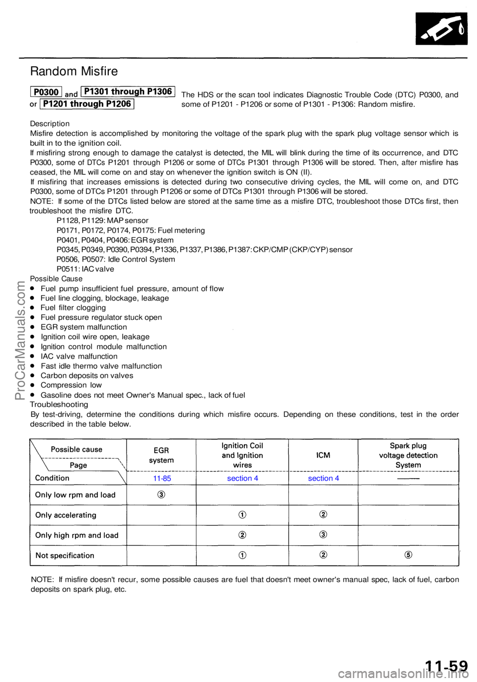
Troubleshootin g
By test-driving , determin e th e condition s during which misfir e occurs . Dependin g o n thes e conditions , tes t i n th e orde r
describe d i n th e tabl e below .
NOTE : I f misfir e doesn' t recur , som e possibl e cause s ar e fue l tha t doesn' t mee t owner' s manua l spec , lac k o f fuel , carbo n
deposit s o n spar k plug , etc .
11-8 5 sectio n 4 section 4
ProCarManuals.com
Page 178 of 1954

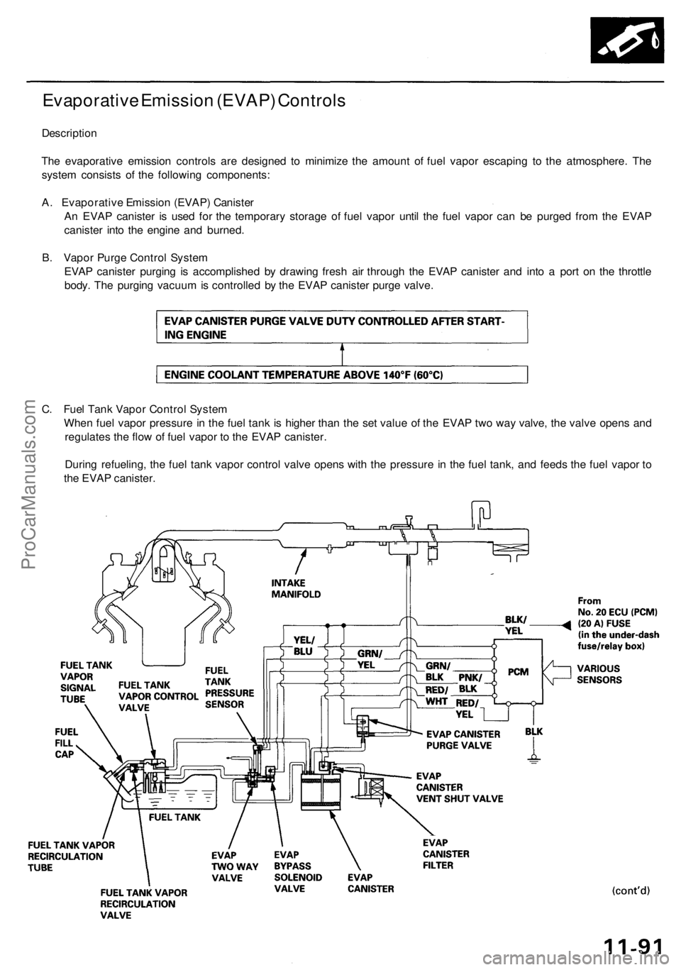
Evaporative Emission (EVAP) Controls
Description
The evaporative emission controls are designed to minimize the amount of fuel vapor escaping to the atmosphere. The
system consists of the following components:
A. Evaporative Emission (EVAP) Canister
An EVAP canister is used for the temporary storage of fuel vapor until the fuel vapor can be purged from the EVAP
canister into the engine and burned.
B. Vapor Purge Control System
EVAP canister purging is accomplished by drawing fresh air through the EVAP canister and into a port on the throttle
body. The purging vacuum is controlled by the EVAP canister purge valve.
C. Fuel Tank Vapor Control System
When fuel vapor pressure in the fuel tank is higher than the set value of the EVAP two way valve, the valve opens and
regulates the flow of fuel vapor to the EVAP canister.
During refueling, the fuel tank vapor control valve opens with the pressure in the fuel tank, and feeds the fuel vapor to
the EVAP canister.ProCarManuals.com
Page 373 of 1954

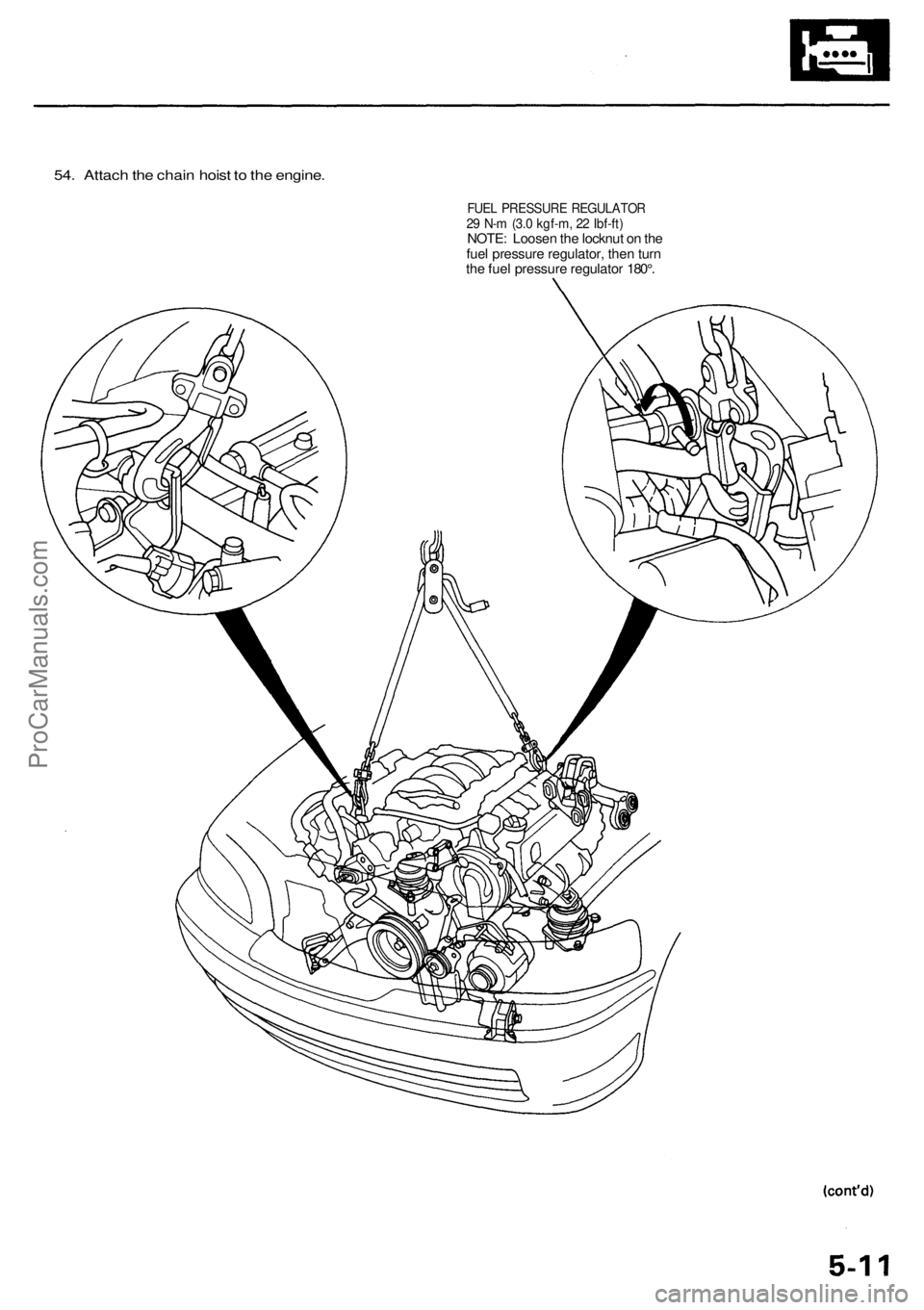
54. Attach the chain hoist to the engine.
FUEL PRESSURE REGULATOR
29 N-m (3.0 kgf-m, 22 Ibf-ft)
NOTE: Loosen the locknut on the
fuel pressure regulator, then turn
the fuel pressure regulator 180°.ProCarManuals.com
Page 512 of 1954

'00 - 01 models:
Vacuum hose No.
LEFT PRIMARY HEATED OXYGEN SENSOR (LEFT PRIMARY
HO2S) (BANK 2, SENSOR 1)
RIGHT PRIMARY HEATED OXYGEN SENSOR (RIGHT
PRIMARY
HO2S) (BANK
1,
SENSOR
1)
SECONDARY HEATED OXYGEN SENSOR (SECONDARY
HO2S) (SENSOR 2)
MANIFOLD ABSOLUTE PRESSURE (MAP) SENSOR
INTAKE AIR TEMPERATURE (IAT) SENSOR
LEFT KNOCK SENSOR (BANK 2)
RIGHT KNOCK SENSOR (BANK 1)
IDLE AIR CONTROL (IAC) VALVE
IDLE AIR CONTROL (IAC) THERMAL VALVE
THROTTLE BODY
IDLE ADJUSTING SCREW
INJECTOR
FUEL PULSATION DAMPER
FUEL FILTER
FUEL PRESSURE REGULATOR
PRESSURE REGULATOR VACUUM CONTROL SOLENOID
VALVE
FUEL PUMP
FUEL TANK
FUEL TANK VAPOR CONTROL VALVE
FUEL TANK VAPOR RECIRCULATION VALVE
AIR CLEANER
RESONATOR
INTAKE MANIFOLD RUNNER CONTROL (IMRC) CHECK
VALVE
INTAKE MANIFOLD RUNNER CONTROL (IMRC) VACUUM
RESERVOIR
INTAKE MANIFOLD RUNNER CONTROL (IMRC) SOLENOID
VALVE 1
INTAKE MANIFOLD RUNNER CONTROL (IMRC)
DIAPHRAGM 1
INTAKE MANIFOLD RUNNER CONTROL (IMRC) SOLENOID
VALVE 2
INTAKE MANIFOLD RUNNER CONTROL (IMRC)
DIAPHRAGM 2
EXHAUST GAS RECIRCULATION (EGR) VALVE VACUUM
CONTROL VALVE
EXHAUST GAS RECIRCULATION (EGR) VALVE VACUUM
CONTROL SOLENOID VALVE
EXHAUST GAS RECIRCULATION (EGR) VALVE and POSI-
TION SENSOR
POSITIVE CRANKCASE VENTILATION (PCV) VALVE
EVAPORATIVE EMISSION (EVAP) CANISTER PURGE VALVE
EVAPORATIVE EMISSION (EVAP) CANISTER
EVAPORATIVE EMISSION (EVAP) CANISTER VENT SHUT
VALVE
EVAPORATIVE EMISSION (EVAP) CANISTER FILTER
EVAPORATIVE EMISSION (EVAP) TWO WAY VALVE
EVAPORATIVE EMISSION (EVAP) BYPASS SOLENOID
VALVE
FUEL TANK PRESSURE (FTP) SENSOR
THREE WAY CATALYTIC CONVERTER (TWC)
ENGINE MOUNT CONTROL SOLENOID VALVEProCarManuals.com
Page 544 of 1954

PCM Data
You can retrieve data from the PCM by connecting the OBD II scan tool or the Honda PGM Tester to the Data Link
Connector (DLC). The items listed in the table below conform to SAE recommended practice. The Honda PGM Tester also
reads data beyond that recommended by SAE so that this data may help you find the causes of intermittent problems.
NOTE:
• The "operating values" listed are approximate and may vary depending on the environment and the individual vehicle.
• Unless noted otherwise, "at idle speed" means idling with the engine completely warmed up, transmission in Park or
neutral, and the A/C and all accessories turned off.
Data
Description
Operating Value
Freeze Data
Diagnostic
Trouble Code
(DTC)
If the PCM detects a problem, it will store it as a code
consisting of one letter and four numbers.
Depending on the problem, an SAE-defined code
(P0xxx)
or a
Honda-defined code
(P1xxx)
will
be
output
to the tester.
If no problem is detected,
there is no output.
YES
Engine Speed
The PCM computes engine speed from the signals sent
from the Crankshaft Position (CKP) sensor.
This data is used for determining the time and amount
of fuel injection.
Nearly the same as
tachometer indication at
idle speed:
650 ± 50 rpm
YES
Vehicle Speed
The PCM converts pulse signals from the Vehicle
Speed Sensor (VSS) into speed data.
Nearly the same as
speedometer indication
YES
Manifold
Absolute
Pressure (MAP)
The absolute pressure created in the intake manifold by
engine load and speed.
With engine stopped:
Nearly the same as atmo-
spheric pressure.
At idle speed:
24 - 37
kPa
(180
-
280
mmHg, 7.1 - 11.0 inHg)
YES
Engine Coolant
Temperature
(ECT)
The ECT sensor converts coolant temperature into
voltage and signals the PCM. The sensor is a thermistor
whose internal resistance changes with coolant
temperature. The PCM uses the voltage signals from
the ECT sensor to determine the amount of injected
fuel.
With cold engine:
Same as ambient temper-
ature and IAT
With engine warmed up:
approx. 158 - 212°F
(70 - 100°C)
YES
Heated Oxygen
Sensor (HO2S)
(Bank 1, Sensor 1)
(Bank 2, Sensor 1)
(Sensor 2)
The HO2S detects the oxygen content in the exhaust
gas and sends voltage signals to the PCM. Based on
these signals, the PCM controls the air/fuel ratio. When
the oxygen content is high (that is, when the ratio is
leaner than the stoichiometric ratio), the voltage signal
is lower. When the oxygen content is low (that is, when
the ratio is richer than the stoichiometric ratio), the
voltage signal is higher.
0.0 -
1.25
V
At idle speed:
about 0.1 - 0.9 V
NOProCarManuals.com
Page 558 of 1954

PGM-FI Syste m
System Descriptio n
INPUTSPOWERTRAI N CONTRO L MODUL E (PCM )OUTPUT S
CKP/CYP Senso r
Cruise
Control
Signal ('04)MA P Senso rECT Senso rIAT Senso rTP Senso rEGR Valv e Positio n Senso rLeft Primar y HO2 SRight Primar y HO2 SSecondar y HO2 SVSSBAR O Senso rLeft Knoc k Senso rRight Knoc k Senso rTCS Signals *VSA Signals*1
Spar k Plu g Voltag e Detectio nModule Signa lStarte r Signa lALT F R Signa lAir Conditionin g Signa lTransmissio n Rang e Switc h Signa lBattery Voltag e (IGN.1 )Brake Peda l Positio n Switc h Signa lPSP Switc h Signa lImmobilize r Signa lFTP Senso rCountershaf t Spee d Senso rMainshaf t Spee d Senso r
Idle Ai r Injecto r Timin g an d Duratio n
Other Contro l Function s
Ignition Timin g Contro l
PCM Back-u p Function s
InjectorsPGM-FI Mai n Rela y (Fue l Pump )Fuel Pum p Rela yMILD4 Indicato r Ligh tIAC Valv eA/C Compresso r Clutc h Rela yICMEVA P Caniste r Purg e Valv eLeft Primar y HO2 S Heate rRight Primar y HO2 S Heate rSecondar y HO2 S Heate rEGR Valv e Vacuu m Contro l Valv ePressur e Regulato r Vacuu mControl Solenoi d Valv eIMRC Solenoi d Valv e 1IMR C Solenoi d Valv e 2DL CTorqu e Converte r Clutc h Solenoi dValveShift Solenoi d Valv eA/T Clutc h Pressur e Contro lSolenoid Valv eEVAP Bypas s Solenoi d Valv eEVAP Caniste r Ven t Shu t Valv eEngin e Moun t Contro l Solenoi dValve
PGM-F I Syste m
Th e PGM-F I syste m o n thi s mode l i s a sequentia l multipor t fue l injectio n system .
Injecto r Timin g an d Duratio n
Th e PC M contain s memorie s fo r th e basi c discharg e duration s a t variou s engin e speed s an d manifol d pressures . Th e
basi c discharg e duration , afte r bein g rea d ou t fro m th e memory , i s furthe r modifie d b y signal s sen t fro m variou s sensor s
t o obtai n th e fina l discharg e duration .
Idl e Ai r Contro l
Idl e Ai r Contro l Valv e (IA C Valve )
Whe n th e engin e i s cold , th e A/ C compresso r i s on , th e transmissio n i s i n gear , th e brak e peda l i s depressed , th e powe r
steerin g loa d i s high , o r th e alternato r i s charging , th e PC M control s curren t t o th e IA C Valv e t o maintai n th e correc t idl e
speed .
Ignition Timin g Contro l
• Th e PC M contain s memorie s fo r basi c ignitio n timin g a t variou s engin e speed s an d manifol d ai r flo w rates . Ignitio n
timin g i s als o adjuste d fo r engin e coolan t temperature .
• A knoc k contro l syste m is als o used . Whe n detonatio n i s detecte d b y a knoc k sensor , th e ignitio n timin g is retarded .
Othe r Contro l Function s
1 . Startin g Contro l
Whe n th e engin e is started , th e PC M provide s a ric h mixtur e b y increasin g injecto r duration .
2 . Fue l Pum p Contro l
• Whe n th e ignitio n switc h i s initiall y turne d on , th e PC M supplie s groun d t o th e PGM-F I mai n rela y tha t supplie s cur -
ren t t o th e fue l pum p fo r 2 second s t o pressuriz e th e fue l system .
• Whe n th e engin e is running , th e PC M supplie s groun d to th e PGM-F I mai n rela y tha t supplie s current to th e fue l pump .
• Whe n th e engin e is no t runnin g an d th e ignitio n i s on , th e PC M cut s groun d t o th e PGM-F I mai n rela y whic h cut s
curren t t o th e fue l pump .
*: wit h TC S*1: wit h VS A
Idle Ai r Contro l
Coolant Temperature Gauge ('04)
ProCarManuals.com