1996 ACURA RL KA9 battery replacement
[x] Cancel search: battery replacementPage 309 of 1954

Lubrication Points
For the details of lubrication points and types of lubricants to be applied, refer to the Illustrated Index and various work
procedures (such as Assembly/Reassembly, Replacement, Overhaul, Installation, etc.) contained in each section.
No.
1
2
3
4
5
6
7
8
9
10
11
12
13
14
15
16
17
18
19
20
21
22
LUBRICATION POINTS
Engine
Transmission
Brake line (Includes ABS line)
Power steering gearbox
Steering boots
Throttle cable end
Steering ball joints
Shift lever (Automatic transmission)
Pedal linkage
Intermediate shaft
Brake master cylinder pushrod
Fuel
fill
lid
Battery terminals
Trunk hinges and latch
Door hinges upper and lower
Door opening detents
Hood hinges and hood latch
Brake line joints (Front and rear wheelhouse)
Caliper Piston boot, caliper
Pins and boots
Power steering system
Differential
A/C compressor
API SERVICE LABEL API CERTIFICATION SEAL
LUBRICANT
API Service Grade: Use SJ "Energy Conserving" grade oil.
The oil container may also display the API Certification
seal shown below. Make sure it says "For Gasoline
Engines."
SAE Viscosity: See chart below.
Honda ATF-Z1 (ATF)*1
Genuine Honda DOT3 brake fluid*2
Steering grease P/N 08733 - B070E
Multi-purpose grease
Honda White Lithium Grease
Rust preventive
Silicone grease
Genuine Honda power steering fluid*3
Hypoid gear Oil API GL4 or GL5
Viscosity:
at above -18°C (0°F): SAE 90
at less than -18°C (0°F): SAE 80W-90
Compressor oil:
DENSO: ND-OIL8 (P/N) 38897 - PR7 - A01 AH or 38899 -
PR7-A01)
(For Refrigerant: HFC-134a (R-134a))
Recommended engine oil
viscosity for ambient
temperature ranges
*1: Always use Honda ATF-Z1 (ATF). Using a non-Honda ATF can affect shift quality.
*2: Always use Genuine Honda DOT3 Brake Fluid. Using a non-Honda brake fluid can cause corrosion and decrease the
life of the system.
*3: Always use Genuine Honda Power Steering Fluid. Using any other type of power steering fluid or automatic transmis-
sion fluid can cause increased wear and poor steering in cold weather.ProCarManuals.com
Page 358 of 1954
Cruise Control
Set/Resume/Cancel Switch Test/Replacement (cont'd)
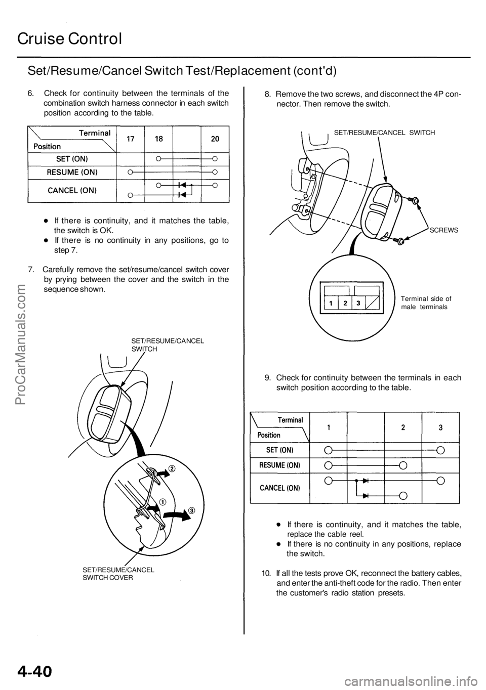
6. Check for continuity between the terminals of the
combination switch harness connector in each switch
position according to the table.
If there is continuity, and it matches the table,
the switch is OK.
If there is no continuity in any positions, go to
step 7.
7. Carefully remove the set/resume/cancel switch cover
by prying between the cover and the switch in the
sequence shown.
SET/RESUME/CANCEL
SWITCH
SET/RESUME/CANCEL
SWITCH COVER
8. Remove the two screws, and disconnect the 4P con-
nector. Then remove the switch.
SET/RESUME/CANCEL SWITCH
SCREWS
9. Check for continuity between the terminals in each
switch position according to the table.
If there is continuity, and it matches the table,
replace the cable reel.
If there is no continuity in any positions, replace
the switch.
10. If all the tests prove OK, reconnect the battery cables,
and enter the anti-theft code for the radio. Then enter
the customer's radio station presets.
Terminal side of
male terminalsProCarManuals.com
Page 822 of 1954
Shift Solenoid Valves A and B
Test
Replacement
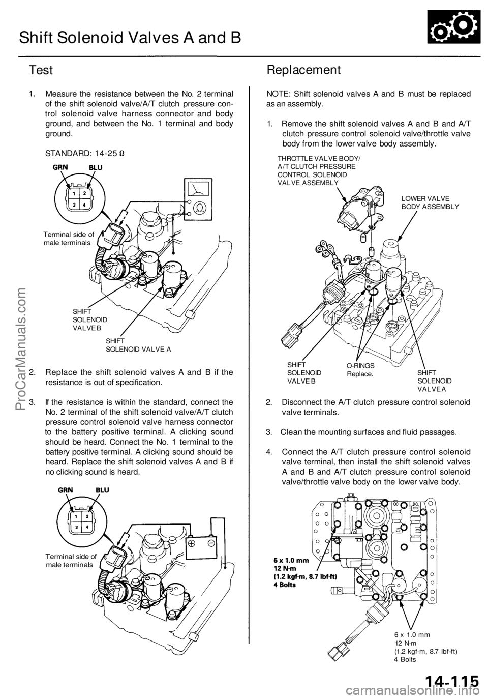
Measure the resistance between the No. 2 terminal
of the shift solenoid valve/A/T clutch pressure con-
trol solenoid valve harness connector and body
ground, and between the No. 1 terminal and body
ground.
Terminal side of
male terminals
SHIFT
SOLENOID
VALVE B
SHIFT
SOLENOID VALVE A
2. Replace the shift solenoid valves A and B if the
resistance is out of specification.
3. If the resistance is within the standard, connect the
No. 2 terminal of the shift solenoid valve/A/T clutch
pressure control solenoid valve harness connector
to the battery positive terminal. A clicking sound
should be heard. Connect the No. 1 terminal to the
battery positive terminal. A clicking sound should be
heard. Replace the shift solenoid valves A and B if
no clicking sound is heard.
Terminal side of
male terminals
NOTE: Shift solenoid valves A and B must be replaced
as an assembly.
1. Remove the shift solenoid valves A and B and A/T
clutch pressure control solenoid valve/throttle valve
body from the lower valve body assembly.
THROTTLE VALVE BODY/
A/T CLUTCH PRESSURE
CONTROL SOLENOID
VALVE ASSEMBLY
LOWER VALVE
BODY ASSEMBLY
SHIFT
SOLENOID
VALVE B
O-RINGS
Replace.
SHIFT
SOLENOID
VALVE A
2. Disconnect the A/T clutch pressure control solenoid
valve terminals.
3. Clean the mounting surfaces and fluid passages.
4. Connect the A/T clutch pressure control solenoid
valve terminal, then install the shift solenoid valves
A and B and A/T clutch pressure control solenoid
valve/throttle valve body on the lower valve body.
6 x 1.0 mm
12 N-m
(1.2 kgf-m, 8.7 Ibf-ft)
4 Bolts
STANDARD: 14-25ProCarManuals.com
Page 1239 of 1954
Troubleshooting Precaution s
System Indicator s
If th e syste m is OK , th e AB S indicato r goe s of f onc e afte r turnin g th e ignitio n switc h O N (II ) withou t startin g th e engine ,
an d the n com e o n agai n an d g o of f severa l second s late r afte r startin g th e engine . Thi s occur s becaus e th e VS A contro l
uni t i s turne d o n b y th e IG 2 powe r source .
Th e AB S indicato r o r VS A syste m indicato r come s o n whe n th e VS A contro l uni t detect s a proble m in th e system .
Th e AB S indicato r o r VS A syste m indicato r wil l als o com e o n unde r thes e conditions , eve n thoug h th e syste m is oper -
atin g properly :
— Th e vehicl e goe s int o a spi n
— Th e AB S continue s t o operat e fo r a lon g tim e
— Th e vehicl e is subjecte d to a n electrica l signa l disturbanc e
I f ther e is a faul t i n th e PGM-F I system , onl y th e VS A syste m indicato r come s on .
Th e VS A Activatio n Indicato r wil l flas h whe n onl y th e driv e wheel s rotat e o r on e o f th e driv e wheel s is stuck . Whe n thi s
occurs , th e AB S indicato r an d VS A syste m indicato r d o no t com e on .
T o determin e th e actua l caus e o f th e problem , questio n th e custome r abou t th e problem , takin g thes e condition s int o con -
sideration .
Whe n a proble m is detecte d an d th e AB S o r VS A indicato r come s on , ther e ar e case s whe n th e indicato r stay s o n unti l
th e ignitio n switc h i s turne d OFF , an d case s whe n th e indicato r goe s of f automaticall y whe n th e syste m return s t o nor -
mal . Fo r DT C 6 1 an d 62 , th e indicato r goe s of f automaticall y whe n th e syste m return s t o normal . Fo r al l othe r codes ,
th e indicato r stay s o n unti l th e ignitio n switc h is turne d OFF .
Fo r DTC s 12 , 14 , 16 , 18 , 51 , 52 , 53 , 66 , 6 8 an d 84 , th e AB S indicato r goe s of f whe n th e vehicl e is drive n agai n an d th e
syste m is O K afte r th e ignitio n switc h is turne d fro m OF F to O N (II) . However , i f th e DT C is cleared , th e CP U reset s an d
th e indicato r goe s of f righ t afte r th e engin e is starte d if th e syste m is OK .
Th e AB S is no t operationa l whe n th e AB S indicato r i s ON ; th e VS A is no t operationa l whe n th e VS A indicato r i s ON .
Whe n th e VS A indicato r an d MI L ar e bot h ON , troubleshoo t th e PGM-F I syste m first .
Diagnosti c Troubl e Cod e (DTC )
Th e memor y ca n hol d an y numbe r o f DTCs . However , whe n th e sam e DT C is detecte d mor e tha n once , th e mor e recen t
DT C is writte n ove r th e earlie r one . Therefore , whe n th e sam e proble m is detecte d repeatedly , i t i s memorize d a s a sin -
gle DTC .
The DTC s ar e indicate d in ascendin g numbe r order , no t i n th e orde r the y occur .
Th e DTC s ar e memorize d in th e EEPRO M (non-volatil e memory) . Therefore , th e memorize d DTC s canno t b e cancele d
b y disconnectin g th e battery . Perfor m th e specifie d procedure s to clea r th e DTCs .
Self-diagnosi s
Self-diagnosis can be classifie d int o tw o categories :
— Initia l diagnosis : Performe d righ t afte r th e engin e start s an d unti l th e AB S o r VS A indicato r goe s off .
— Regula r diagnosis : Performe d righ t afte r th e initia l diagnosi s unti l th e ignitio n switc h is turne d OFF .
When a proble m is detecte d b y self-diagnosis , th e VS A contro l uni t shift s to fail-saf e mode .
Kickbac k
The pum p moto r operate s whe n th e AB S is functioning , an d th e flui d in th e reservoi r i s force d ou t t o th e maste r cylinder ,
causing kickbac k a t th e brak e pedal .
Pum p Moto r
Th e pum p moto r operate s whe n th e AB S is functioning .
The VS A contro l uni t check s th e pum p moto r operatio n durin g initia l diagnosi s whe n th e vehicl e is started .
You ma y hea r th e moto r operat e a t thi s time , bu t i t i s normal .
Brak e Flui d Replacement/Ai r Bleedin g
Brak e flui d replacemen t an d ai r bleedin g procedure s ar e identica l t o th e procedure s us e o n vehicle s no t equippe d wit h
VSA . T o eas e bleeding , star t wit h th e fron t wheels .
ProCarManuals.com
Page 1795 of 1954
Precautions/Procedures
General Precaution s
• Carefull y inspec t an y SR S par t befor e yo u instal l it . D o
no t instal l an y par t tha t show s sign s o f bein g droppe d
o r improperl y handled , suc h a s dents , crack s o r defor -
mation :
Airbag s (fronta l airbag s an d sid e airbags )
Cabl e ree l
SRS uni t
Sea t bel t tensioner s
• Us e onl y a digita l multimete r t o chec k th e system . I f
it' s no t a Hond a multimeter , mak e sur e it s outpu t i s
1 0 m A (0.0 1 A ) o r les s whe n switche d t o th e smalles t
valu e i n th e ohmmete r range . A teste r wit h a highe r
output coul d damag e th e airba g circui t o r caus e acci -
denta l deploymen t an d possibl e injury .
• D o no t instal l use d SR S part s fro m anothe r vehicle .
Whe n makin g SR S repairs , us e onl y ne w parts .
• Excep t whe n performin g electrica l inspections ,
alway s disconnec t bot h th e negativ e cabl e an d posi -
tive cabl e fro m th e battery , an d wai t a t leas t 3 min -
utes befor e beginnin g work .
• Replacemen t o f th e combinatio n ligh t an d wiper /
washe r switche s an d cruis e contro l switc h ca n b e
don e withou t removin g th e steerin g wheel :
For combinatio n ligh t an d wiper/washe r switc h
replacement , se e sectio n 23 .
Fo r cruis e contro l set/resume/cance l switc h
replacement , se e sectio n 4 .
• Wheneve r th e ignitio n switc h is O N (II) , o r ha s bee n
turne d OF F fo r les s tha n 3 minutes , b e carefu l no t t o
bum p th e SR S unit ; th e airbag s coul d accidentall y
deplo y an d caus e damag e o r injury .
• Wheneve r th e airbag s hav e bee n activated , replac e
th e sea t bel t tensioner s an d th e SR S unit .
• Th e origina l radi o ha s a code d thef t protectio n circuit .
B e sur e to ge t th e customer' s cod e numbe r befor e dis -
connectin g th e batter y cables .
• Th e PC M memor y mus t b e rese t afte r reconnectin g th e
batter y (se e pag e 11-125 ).
Airba g Handlin g an d Storag e
Do no t tr y t o disassembl e an y o f th e airbags , fronta l o r
side . The y hav e n o serviceabl e parts . Onc e a n airba g
ha s bee n operate d (deployed) , i t canno t b e repaire d o r
reused .
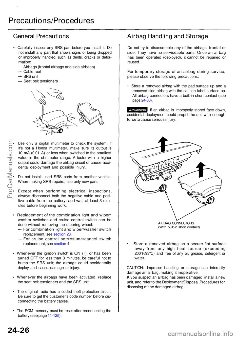
For temporar y storag e o f a n airba g durin g service ,
please observ e th e followin g precautions :
• Stor e a remove d airba g wit h th e pa d surfac e u p an d a
remove d sid e airba g wit h th e cautio n labe l surfac e up .
Al l airba g connector s hav e a built-i n shor t contac t (se e
page 24-30 ).
If a n airba g is improperl y store d fac e down ,
accidenta l deploymen t coul d prope l th e uni t wit h enoug h
forc e to caus e seriou s injury .
AIRBA G CONNECTOR S(With built-i n shor t contact )
• Stor e a remove d airba g o n a secur e fla t surfac e
awa y fro m an y hig h hea t sourc e (exceedin g
200°F/93°C ) an d fre e o f an y oil , grease , detergen t o r
water .
CAUTION : Imprope r handlin g o r storag e ca n internall y
damag e a n airbag , makin g it inoperative .
K yo u suspec t a n airba g ha s bee n damaged , instal l a ne w
unit , an d refe r t o th e Deployment/Disposa l Procedure s fo r
disposin g o f th e damage d airbag .
ProCarManuals.com
Page 1952 of 1954
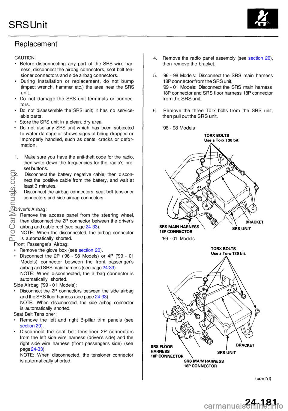
SRS Uni t
Replacemen t
CAUTION:
• Befor e disconnectin g an y par t o f th e SR S wir e har -
ness , disconnec t th e airba g connectors , sea t bel t ten -
sione r connector s an d sid e airba g connectors .
• Durin g installatio n o r replacement , d o no t bum p
(impac t wrench , hamme r etc. ) th e are a nea r th e SR S
unit.
• D o no t damag e th e SR S uni t terminal s o r connec -
tors.
• D o no t disassembl e th e SR S unit ; i t ha s n o service -
abl e parts .
• Stor e th e SR S uni t i n a clean , dr y area .
• D o no t us e an y SR S uni t whic h ha s bee n subjecte d
t o wate r damag e o r show s sign s o f bein g droppe d o r
improperl y handled , suc h a s dents , crack s o r defor -
mation .
1. Mak e sur e yo u hav e th e anti-thef t cod e fo r th e radio ,
the n writ e dow n th e frequencie s fo r th e radio' s pre -
set buttons .
2. Disconnec t th e batter y negativ e cable , the n discon -
nec t th e positiv e cabl e fro m th e battery , an d wai t a t
leas t 3 minutes .
3. Disconnec t th e airba g connectors , sea t bel t tensione r
connector s an d sid e airba g connectors .
Driver' s Airbag :
• Remov e th e acces s pane l fro m th e steerin g wheel ,
the n disconnec t th e 2 P connecto r betwee n th e driver' s
airba g an d cabl e ree l (se e pag e 24-33 ).
NOTE : Whe n th e disconnected , th e airba g connecto r
i s automaticall y shorted .
Fron t Passenger' s Airbag :
• Remov e th e glov e bo x (se e sectio n 20 ).
• Disconnec t th e 2 P ('9 6 - 9 8 Models ) o r 4 P ('9 9 - 0 1
Models ) connecto r betwee n th e fron t passenger' s
airba g an d SR S mai n harnes s (se e pag e 24-33 ).
NOTE : Whe n disconnected , th e airba g connecto r i s
automaticall y shorted .
Sid e Airba g ('9 9 - 0 1 Models) :
• Disconnec t th e 2 P connector s betwee n th e sid e airba g
an d th e SR S floo r harnes s (se e pag e 24-33 ).
NOTE : Whe n disconnected , th e sid e airba g connecto r
i s automaticall y shorted .
Sea t Bel t Tensioner :
• Remov e th e lef t an d righ t B-pilla r tri m panel s (se e
sectio n 20 ).
• Disconnec t th e sea t bel t tensione r 2 P connector s
fro m th e lef t sid e wir e harnes s (driver' s side ) an d th e
righ t sid e wir e harnes s (fron t passenger' s side ) (se e
pag e 24-33 ).
NOTE : Whe n disconnected , th e tensione r connecto r
is automaticall y shorted .
'99 - 0 1 Model s
4
. Remov e th e radi o pane l assembl y (se e sectio n 20 ),
the n remov e th e bracket .
5 . '9 6 - 9 8 Models : Disconnec t th e SR S mai n harnes s
18P connecto r fro m th e SR S unit .
'99 - 0 1 Models : Disconnec t th e SR S mai n harnes s
18P connecto r an d SR S floo r harnes s 18 P connecto r
from th e SR S unit .
6. Remov e th e thre e Tor x bolt s fro m th e SR S unit ,
then pul l ou t th e SR S unit .
'96 - 9 8 Model s
ProCarManuals.com
Page 1954 of 1954
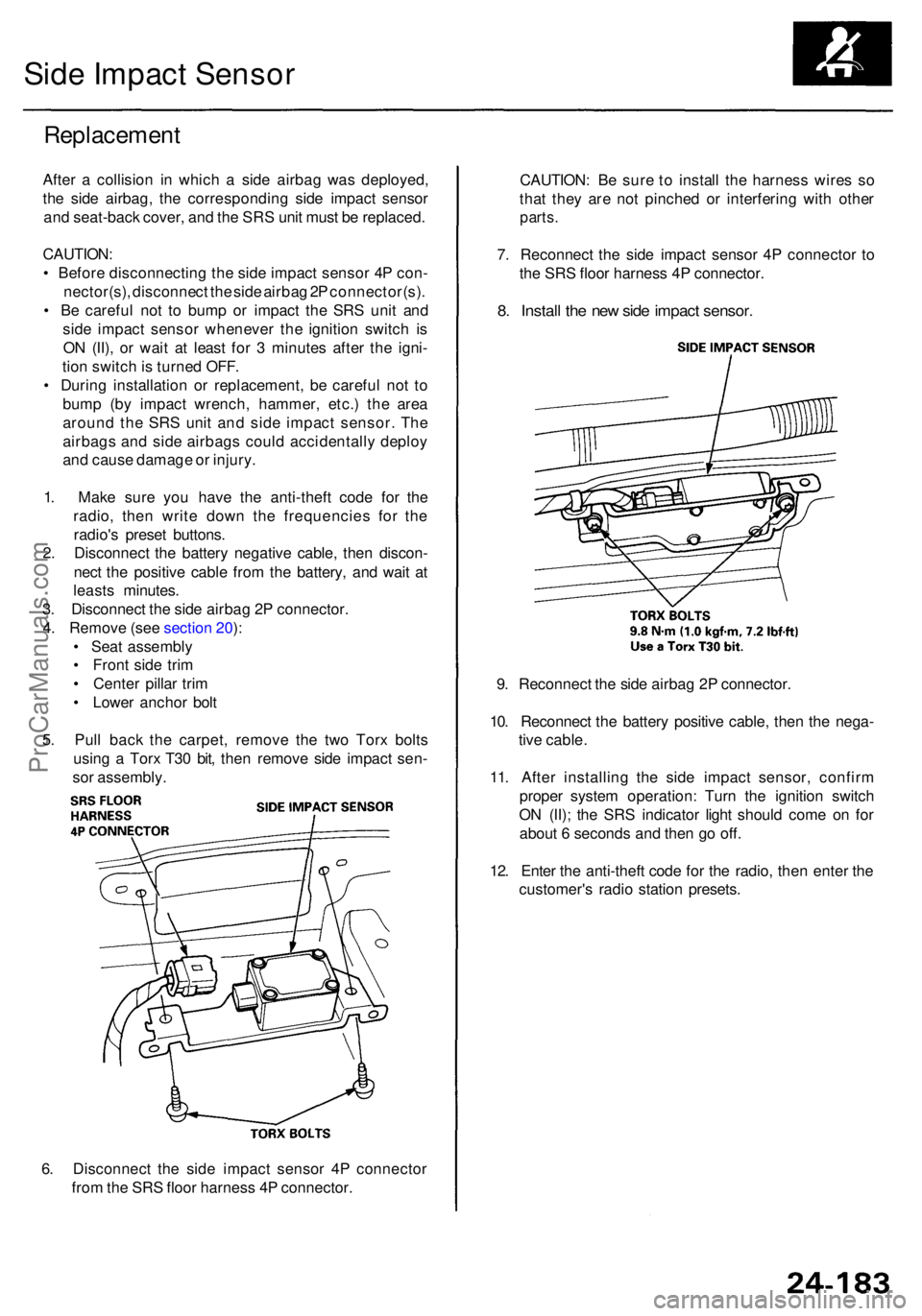
6. Disconnec t th e sid e impac t senso r 4 P connecto r
fro m th e SR S floo r harnes s 4 P connector .
Replacemen t
After a collisio n i n whic h a sid e airba g wa s deployed ,
th e sid e airbag , th e correspondin g sid e impac t senso r
an d seat-bac k cover , an d th e SR S uni t mus t b e replaced .
CAUTION :
• Befor e disconnectin g th e sid e impac t senso r 4 P con -
nector(s) , disconnec t th e sid e airba g 2 P connector(s) .
• B e carefu l no t t o bum p o r impac t th e SR S uni t an d
sid e impac t senso r wheneve r th e ignitio n switc h i s
O N (II) , o r wai t a t leas t fo r 3 minute s afte r th e igni -
tio n switc h is turne d OFF .
• Durin g installatio n o r replacement , b e carefu l no t t o
bum p (b y impac t wrench , hammer , etc. ) th e are a
aroun d th e SR S uni t an d sid e impac t sensor . Th e
airbag s an d sid e airbag s coul d accidentall y deplo y
an d caus e damag e o r injury .
1 . Mak e sur e yo u hav e th e anti-thef t cod e fo r th e
radio , the n writ e dow n th e frequencie s fo r th e
radio' s prese t buttons .
2 . Disconnec t th e batter y negativ e cable , the n discon -
nec t th e positiv e cabl e fro m th e battery , an d wai t a t
least s minutes .
3 . Disconnec t th e sid e airba g 2 P connector .
4 . Remov e (se e sectio n 20 ):
• Sea t assembl y
• Fron t sid e tri m
• Cente r pilla r tri m
• Lowe r ancho r bol t
5 . Pul l bac k th e carpet , remov e th e tw o Tor x bolt s
usin g a Tor x T3 0 bit , the n remov e sid e impac t sen -
so r assembly .
Side Impac t Senso r
CAUTION : B e sur e t o instal l th e harnes s wire s s o
tha t the y ar e no t pinche d o r interferin g wit h othe r
parts.
7. Reconnec t th e sid e impac t senso r 4 P connecto r t o
th e SR S floo r harnes s 4 P connector .
8. Instal l th e ne w sid e impac t sensor .
9. Reconnec t th e sid e airba g 2 P connector .
10 . Reconnec t th e batter y positiv e cable , the n th e nega -
tiv e cable .
11 . Afte r installin g th e sid e impac t sensor , confir m
prope r syste m operation : Tur n th e ignitio n switc h
O N (II) ; th e SR S indicato r ligh t shoul d com e o n fo r
abou t 6 second s an d the n g o off .
12 . Ente r th e anti-thef t cod e fo r th e radio , the n ente r th e
customer' s radi o statio n presets .
ProCarManuals.com